Transcription
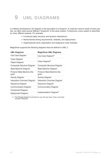
9UML DIAGRAMSIn software development, the diagram is the equivalent of a blueprint. To meet the various needs of many parties, we often need several different “blueprints” of the same system. Furthermore, every system is describedby many different aspects. For example: Functional (static structure and dynamic interactions) Nonfunctional (timing requirements, reliability, and deployment) Organizational (work organization and mapping to code modules)MagicDraw supports the following diagrams that are defined in UML 2:UML DiagramsMagicDraw UML DiagramsUse Case DiagramUse Case DiagramaClass DiagramObject DiagramClass DiagramaComposite Structure DiagramComposite Structure DiagramState Machine DiagramState Machine DiagramProtocol State Machine DiagramProtocol State Machine DiagramActivity DiagramActivity DiagramInteraction Overview DiagramInteraction Overview DiagramSequence DiagramSequence DiagramCommunication DiagramCommunication DiagramComponent DiagramDeployment DiagramImplementation Diagramaa. The Package Diagram is provided for use with Use Case, Class, and Implementation Diagrams472Copyright 1998-2010 No Magic, Inc.
9UML DIAGRAMSArchitectural ViewsArchitectural ViewsUML defines 13 diagrams that describe 4 1 architectural views:Figure 334 -- Architectural ViewsSeveral kinds of diagrams provide a visual notation for the concepts in each view.Use Case ViewThe use case view represents the functionality and behavior of a system or subsystem as it is perceived byexternal users. This view is targeted mainly at customers, designers, developers, and testers.The use case view usually is presented as a number of use cases and actors in Use Case diagrams. Occasionally it is used in Activity and Sequence diagrams.The use case view is central because the contents drive the development of the other views. It is also used forproject planning. Every single use case unit is deemed as a manageable unit during the project execution.Structural ViewThe structural view represents structural elements for implementing a solution for defined requirements. It identifies all of the business entities and how these entities are related to each other. Usually entities are represented as classifiers and their instances in class and object diagrams in multiple abstraction levels. Systemdecomposition to different layers can be displayed using Package diagrams. A Composite structure diagramcan be used to represent the classifier inner structure. The system structural view artifacts are created by software architects and represent the system implementation design solutions.Behavioral ViewThe dynamic behavior of the system is displayed on the Interaction (sequence and collaboration), State, Activity, Interaction overview, and Timing diagrams. It focuses mainly on the interactions that occur between objectsinside a system, activities and work performed by the various parts of a system, and state changes within a particular object or collaboration. Rather than defining the participants of the system, it defines how particular usecases are executed, which provides value for the external user. The dynamic view is concerned about what ishappening inside the system and how those actions impact other participants.473Copyright 1998-2010 No Magic, Inc.
9UML DIAGRAMSClass DiagramImplementation viewThe implementation view describes the implementation artifacts of logical subsystems defined in the structuralview. It may include the intermediate artifacts used in a system construction (code files, libraries, data files,etc.) This view defines dependencies between the implementation components and their connections by therequired and provided interfaces. Components and their relationships are displayed on the Component diagram. Inner parts of the component can be represented with the Composite structure diagrams. The implementation view helps analyze system parts and their dependencies in a higher component level.Environment viewThe environment view represents the physical arrangement of a system, such as computers and devices(nodes) and how they are connected to each other. In contrast to the component view, the deployment view isconcerned with the physical structure of the system and the location of the software modules (components)manifested by artifacts within the system.The environment view is displayed on the deployment diagram that is called the implementation diagram inMagicDrawTM UML.Class DiagramA class diagram is a graphic representation of the static structural model. It shows classes and interfaces,along with their internal structure and relationships. The classes represent types of objects that are handled ina system. A class diagram does not show temporal information, it describes only the classification. Theinstances of those types (objects) are instantiated only on the runtime and are represented by an object and theinteraction diagrams.The classes can be related to each other in a number of ways: associated (connected to each other), dependent (one class depends/uses another class), specialized (one class is a subtype of another class), or packaged (grouped together as a unit – package). A class diagram does not express anything specific about therelationships of a given object, but it does abstractly describe the potential relationships of one object with otherobjects.A system typically has a number of class diagrams – not all classes are inserted into a single class diagram. Aclass may have multiple levels of meaning and participate in several class diagrams.A class diagram is the logical map of an existing or future source code.The classes can be grouped into packages. The packages can be nested within other packages. A package, asan entity, may have all the relationships that can be drawn for a class. Those relationships are derived from theclasses or packages that are nested within two particular packages (i.e., the relationship between packagesreflects a set of relationships between classes placed in those packages).474Copyright 1998-2010 No Magic, Inc.
9UML DIAGRAMSClass DiagramClass diagram elementsModel elementButton (hotkey)NotationClassA descriptor for a set ofobjects with similar structures, behaviors, and(C)relationships.EnumerationA user-defined data typewhose instances are aset of user-specified(K)named enumeration literals. The literals have arelative order but no algebra is defined on them.Class by Pattern(SHIFT P)SignalData TypePrimitive TypeInterfaceThe description of a visible behavior of a class, acomponent or a package.Attributes and operations inside the Interfacecan be suppressed.475(I)Copyright 1998-2010 No Magic, Inc.
9UML DIAGRAMSClass DiagramModel elementButton (hotkey)NotationPackageA group of classes andother model elements.(P)ModelA model is an abstractionof a physical system froma particular point of view.A model contains a hierarchy of packages/subsystems and other modelelements that describethe system.(M)GeneralizationA relationship between amore general and a morespecific element.(G)Note: Choose a differentGeneralization directionfrom the toolbar to draw aline with an oppositearrow end.AssociationA connection amongclasses, which alsomeans a connectionamong objects of thoseclasses.(S)Directed AssociationNon-navigableAssociation476Copyright 1998-2010 No Magic, Inc.
9UML DIAGRAMSClass DiagramModel elementN-ary associationAn association amongtwo or more classes (asingle class may appearmore than once).Button (hotkey)Notation(O)Association ClassThe Association Class isa declaration of a semantic relationship betweenClassifiers. The Association Class, which has aset of features of its own,is both an Associationand a Class.AggregationAn aggregation is anassociation that represents a whole-part relationship.(A)Directed AggregationCompositionA composition is a formof aggregation with astronger ownership andcoincident lifetime of partwith the whole.(F)Directed Composition477Copyright 1998-2010 No Magic, Inc.
9UML DIAGRAMSClass DiagramModel elementButton (hotkey)NotationInterface RealizationA relationship is usuallyused between an interface and an implementation class.(R)Note: Choose a differentInterface Realizationdirection from the toolbarto draw a line with anopposite arrow end.RealizationA relationship between aspecification and itsimplementation.(E)SubstitutionA substitution is a relationship between twoclassifiers.UsageA usage is a relationshipin which one elementrequires another element (or set of elements)for its full implementationor operation.Note: Choose a differentUsage direction from thetoolbar to draw a line withan opposite arrow end.AbstractionAn abstraction is adependency relationshipthat relates two elementsor sets of elements thatrepresent the same concept at different levels ofabstraction or from different viewpoints.Template BindingA binding is a relationshipbetween a template anda model element generated from the template.478(B)Copyright 1998-2010 No Magic, Inc.
9UML DIAGRAMSClass DiagramModel elementButton (hotkey)NotationPackage MergeA package merge is adirected relationshipbetween two packagesthat indicates that thecontents of the two packages are to be combined.Package ImportA package import isdefined as a directedrelationship that identifiesa package whose members are to be importedby a namespace.Element ImportAn element import isdefined as a directedrelationship between animporting namespaceand a packageable element.Instance(SHIFT O)LinkA connection betweentwo or more objects.(SHIFT L)Profiling Mechanism ToolbarStereotypeA stereotype is an extension mechanism thatdefines a new and morespecialized element ofthe model based on anexisting element.(SHIFT S)MetaClassA class whose instancesare classes. Metaclasses are typically usedto construct metamodels.ExtensionAn extension is used toindicate that the properties of a metaclass areextended through a stereotype, and gives theability to flexibly add (andlater remove) stereotypesto classes.479Copyright 1998-2010 No Magic, Inc.
9UML DIAGRAMSUse Case DiagramModel elementButton (hotkey)NotationProfileA Profile is a kind ofPackage that extends areference metamodel.Profile ApplicationA profile application isused to show which profiles have been applied toa package.Use Case DiagramA use case is a description of the functionality (a specific usage of a system) that a system provides. The usecase descriptions may exist in a textual form (a simple table), where the use case diagram provides additionalinformation about the relationship between the use cases and the external users. The diagram also allows adefinition of the system's boundary.The Use cases are described only in terms of how they appear when viewed externally by the user (a system'sbehavior as the user perceives it), and do not describe how the functionality is provided inside the system. TheUse cases are not object-oriented, but they are included in the UML to simplify the approach of the project'slifecycle -- from the specification to the implementation.Figure 335 -- The schematic view of the use cases in the system.480Copyright 1998-2010 No Magic, Inc.
9UML DIAGRAMSUse Case DiagramUse Case diagram s represent roles played byhuman users, external hardware,and other subjects. An actor doesnot necessarily represent a specificphysical entity but merely a particular facet (that is, "role") of some entities that is relevant to thespecification of its associated usecases.Use CaseA use case is a kind of behaviorrelated classifier that represents adeclaration of an offered behavior.(U)Each use case specifies a particularbehavior, possibly including the variants that the subject can perform incollaboration with one or moreactors. The subject of a use casecould be a physical system or anyother element that may initiate abehavior, such as a component, asubsystem, or a class.PackageA group of classes and other modelelements. A package may containother packages.(P)SubsystemA subsystem is treated as anabstract single unit. It groups modelelements by representing the behav- (Y)ioral unit in a physical system.System BoundaryAnother representation of a package.A system boundary element consistsof use cases related by Exclude orInclude (uses) relationships, whichare visually located inside the systemboundary rectangle.481(B)Copyright 1998-2010 No Magic, Inc.
9UML DIAGRAMSCommunication DiagramElementIncludeAn include (uses) relationship fromuse case A to use case B indicatesthat an instance of the use case Awill also contain the behavior asspecified by B.ExtendA relationship from an extending usecase to an extended use case thatspecifies how and when the behavior defined in the extending use casecan be inserted into the behaviordefined in the extended use case.The extension takes place at one ormore specific extension pointsdefined in the extended use case.Button(hotkey)Notation(C)(E)Note: Choose a different Extenddirection from the toolbar to draw aline with an opposite arrow end.AssociationThe participation of an actor in a usecase, i.e. instances of the actor andinstances of the use case communicate with each other. This is the onlyrelationship between actors and usecases.(S)GeneralizationA relationship between a more general and a more specific element.Note: Choose a different Generalization direction from the toolbar todraw a line with an opposite arrowend.(G)Communication DiagramThe Communication diagram illustrates the various static connections between objects, and models their interactions. It also presents a collaboration that contains a set of instances as well as their required relationshipsgiven in a particular context, and includes an interaction that defines a set of messages. These messagesspecify the interaction between the classifier roles within a collaboration that will serve to achieve the desiredresult.A Communication diagram is given in two different forms: at the instance level or at the specification level.482Copyright 1998-2010 No Magic, Inc.
9UML DIAGRAMSCommunication DiagramCommunication Diagram elementsElementButton(hot key)NotationLifelineA lifeline represents an individual participant in the Interaction. The Lifelines(O)represent only one interacting entity.ConnectorSpecifies a link that enablescommunication between twoor more lifelines. Each con(C)nector may be attached totwo or more connectable elements, each representing aset of lifelines.Connector to SelfSelf connector for self-calls.It begins and ends on thesame lifeline.(S)Message to RightMessage to LeftA Message defines a particular communication betweenthe Lifelines of an Interaction. It implies that one objectuses the services of anotherobject, or sends a messageto that object. A communication can be formed by e.g.raising a signal, invoking anOperation, creating ordestroying an Instance.Click on the arrow to expandthe toolbar and choose anappropriate message type.Call Message to RightCall Message to LeftSend Message to RightSend Message to Left483Copyright 1998-2010 No Magic, Inc.
9UML DIAGRAMSSequence DiagramElementButton(hot key)NotationReply Message to RightReply Message to LeftCreate Message to RightCreate Message to LeftDeleta Message to RightDelete Message to LeftSequence DiagramA sequence diagram shows the interaction information with an emphasis on the time sequence. The diagramhas two dimensions: the vertical axis that represents time and the horizontal axis that represents the participating objects. The time axis could be an actual reference point (by placing the time labels as text boxes). Thehorizontal ordering of the objects is not significant to the operation, and you may rearrange them as necessary.484Copyright 1998-2010 No Magic, Inc.
9UML DIAGRAMSSequence DiagramSequence diagram elementsModel elementsButton (hotkey)NotationLifelineRepresents the existence ofan object at a particular time.(O)Activation BarFocus of control. Shows theperiod during which an objectis performing an action eitherdirectly or through a subordinated procedure.Alternatives(SHIFT A)Loop(SHIFT L)Option(SHIFT O)Parallel(SHIFT P)Break(SHIFT B)Negative(SHIFT G)485Copyright 1998-2010 No Magic, Inc.
9UML DIAGRAMSSequence DiagramModel elementsButton (hotkey)NotationCritical Region(SHIFT R)Consider(SHIFT C)Ignore(SHIFT I)Weak Sequencing(SHIFT W)Strict Sequencing(SHIFT S)Assertion(SHIFT R)Interaction UseA reference to interactions,communication diagram,sequence diagram, and timediagram can be created.MessageA communication betweenobjects that conveys information with the expectation thatan action will ensue. Thereceipt of a message is onetype of event.(SHIFT T)(M)Call Message(A)486Copyright 1998-2010 No Magic, Inc.
9UML DIAGRAMSSequence DiagramModel elementsButton (hotkey)NotationSend Message(E)Reply Message(R)Create Message(C)Delete Message(T)Diagonal MessageRequires some time to arrive,during which another actionoccurs.(D)Message to Self(S)Recursive messageA connected set of messagescan be enclosed and markedas iteration.(U)Duration ConstraintA duration defines a valuespecification that specifies thetemporal distance betweentwo time instants.487Copyright 1998-2010 No Magic, Inc.
9UML DIAGRAMSSequence DiagramModel elementsButton (hotkey)NotationTime ConstraintSpecifies the combination ofmin and max timing intervalvalues.Sequence diagram improvementsState InvariantTermThe OMG UML specification (UML 2.2: Superstructure) states:"A StateInvariant is a runtime constraint on the participants of the interaction. Itmay be used to specify a variety of different kinds of constraints, such as valuesof attributes or variables, internal or external states, and so on".State invariant element support is added in sequence diagram:In the Figure 336 on page 489, the State Invariant element is presented in two cases:1. State Invariant with a assigned mystate State.2. State Invariant with a defined constraint Y.p 15.488Copyright 1998-2010 No Magic, Inc.
9UML DIAGRAMSSequence DiagramFigure 336 -- State Invariant in a Sequence diagram489Copyright 1998-2010 No Magic, Inc.
9UML DIAGRAMSSequence DiagramLost / Found MessagesTermsThe OMG UML specification (UML 2.2: Superstructure) states:"A lost message is a message where the sending event occurrence is known,but there is no receiving event occurrence. We interpret this to be because themessage never reached its destination.""A found message is a message where the receiving event occurrence isknown, but there is no (known) sending event occurrence. We interpret this tobe because the origin of the message is outside the scope of the description.This may for example be noise or other activity that we do not want to describein detail.”Figure 337 -- Lost Message in a Sequence diagram490Copyright 1998-2010 No Magic, Inc.
9UML DIAGRAMSState Machine DiagramFigure 338 -- Found message in a Sequence diagramState Machine DiagramThe behavior of objects of a class can be described in terms of states and events, using a state machine connected to the class under construction.The state machine is a specification of the sequence of states through which an object or an interaction goes inresponse to events during its life, together with its responsive actions. The state machine may represent thesequence of states of a particular collaboration (i.e. collection of objects) or even the whole system (which isalso considered a collaboration). The abstraction of all possible states defined in a state machine is similar tothe way class diagrams are abstracted: all possible object types (classes) of a particular system are described.Objects that do not present a very pronounced reactive behavior may always be considered to stay in the samestate. In such a case, their classes do not possess a state machine.State diagrams (also called Statechart diagrams) represent the behavior of entities capable of dynamic behavior by specifying its response to the receipt of event instances. Typically, the state diagrams describe thebehavior of classes, but the statecharts may also describe the behavior of other model entities such as usecases, actors, subsystems, operations, or methods.A state diagram is a graph that represents a state machine. States and various other types of vertices (pseudostates) in the state machine graph are rendered by the appropriate state and pseudostate symbols, whiletransitions are generally rendered by directed arcs that inter-connect them. The states may also contain subdiagrams by physical containment or tiling. Note that every state machine has a top state, which contains all theother elements of the entire state machine. The graphical rendering of this top state is optional.The states are represented by the state symbols, while the transitions are represented by arrows connectingthe state symbols.491Copyright 1998-2010 No Magic, Inc.
9UML DIAGRAMSState Machine DiagramThe state diagram concerns with internal object changes (as opposed to the external object interaction in collaboration). Do not attempt to draw them for all classes in the system, because they are used only for modelinga complex behavior. The state diagram shows all the possible states that objects or collaborations may have,and the events that cause the state to change. An event can be another object that sends a message to it: forexample, that a specified time has elapsed or that some conditions have been fulfilled. A change of a state iscalled a transition. A transition may also have an action connected to it that specifies what should be done inconnection with the state transition.State Machine Diagram elementsNOTEIf a black arrow is placed on a button, right-click the button, to open other available buttons.Model elementsButton(hot key)NotationStateA state models a situationduring which some (usuallyimplicit) invariant conditions(SHIFT S)holds. The invariant mayrepresent a static situationsuch as an object waitingfor some external events tooccur. However, it can alsomodel dynamic conditionssuch as the process of performing some behavior.sComposite StateA composite state eithercontains one region or isdecomposed into two ormore orthogonal regions.Each region has a set ofmutually exclusive disjointsubvertices and a set oftransitions.Orthogonal StateAn orthogonal state is acomposite state with atleast 2 regions.492(SHIFT C)(C)Copyright 1998-2010 No Magic, Inc.
9UML DIAGRAMSState Machine DiagramModel elementsSubmachine StateThe submachine statespecifies the insertion ofthe specification of a submachine state machine.The Submachine state is adecomposition mechanismthat allows factoring ofcommon behaviors andtheir reuse.Button(hot key)Notation(A)InitialDenotes an initial statewhen an object is created.(I)Final StateDenotes an object destruction or the end of a collaboration.(F)Terminate(R)Entry PointThe entry point connectionpoints a reference as thetarget of a transition. This(Y)implies that the target of thetransition is the entry pointpseudostate as defined inthe submachine of the submachine state.Exit PointThe exit point connectionpoints a reference as thesource of a transition. Thisimplies that the source ofthe transition is the exitpoint pseudostate asdefined in the submachineof the submachine statethat has the exit point connection point defined.493(U)Copyright 1998-2010 No Magic, Inc.
9UML DIAGRAMSState Machine DiagramModel elementsButton(hot key)NotationConnection PointReferenceThe Connection point references of a submachine(Z)state can be used as thesources/targets of the transitions. They represententries into or exits out ofthe submachine statemachine referred by thesubmachine state.Deep HistoryRepresents the most recentactive configuration of thecomposite state thatdirectly contains the pseudostate; e.g. the state configuration that was activewhen the composite statewas last exited.(P)Shallow HistoryRepresents the most recentactive substate of its containing state (but not thesubstates of that substate).A composite state can haveat most one shallow historyvertex.(SHIFT R)JunctionThe junction vertices aresemantic-free vertices thatare used to chain togethermultiple transitions. Theyare used to construct thecompound transition pathsbetween states.(J)ChoiceThe choice points are usedto split transition paths. Inthe dynamic choice point, adecision corncerning whichbranch to take is only madeafter the transition fromState1 is taken and thechoice point is reached.494(O)Copyright 1998-2010 No Magic, Inc.
9UML DIAGRAMSProtocol State Machine DiagramModel elementsButton(hot key)NotationFork/Join VerticalHelps to control parallelactions.(G)Fork/Join HorizontalHelps to control parallelactions.(D)TransitionThe starting time for a relative time event may only beomitted for a time eventthat is the trigger of a statemachine.(T)Transition to SelfWhen an object returns tothe same state after thespecified event occurs.(E)Protocol State Machine DiagramA protocol state machine is always defined in the context of a classifier. It specifies which operations of theclassifier can be called, in which state, and under which condition, thus specifying the allowable call sequenceson the classifier’s operations.The protocol state machine presents the possible and permitted transitions on the instances of its context classifier, together with the operations that carry the transitions.In this manner, an instance lifecycle can be created for a classifier, by specifying the order in which the operations can be activated and the states through which the instance progresses during its existence.The Protocol State Machine Diagram is created for use with the Protocol State Machine and the Protocol Transitions.Protocol State Machine Diagram elementsNOTE495Copyright 1998-2010 No Magic, Inc.
9UML DIAGRAMSProtocol State Machine DiagramIf a black arrow is placed on a button, right-click the button to open other available buttons.Model elementsStateThe states of the protocolstate machines areexposed to the users oftheir context classifiers. Aprotocol state representsan exposed stable situation of its context classifier:When an instance of theclassifier is not processingany operation, the user ofthis instance can alwaysknow its configurationstate.Composite StateA composite state eithercontains one region or isdecomposed into two ormore orthogonal regions.Each region has a set ofmutually exclusive disjointsubvertices and a set oftransitions.Orthogonal StateAn orthogonal state is acomposite state with atleast 2 regions.Submachine StateA submachine state specifies the insertion of thespecification of a submachine state machine. Thesubmachine state is adecomposition mechanismthat allows factoring ofcommon behaviors andtheir reuse.Button(hot key)Notation(SHIFT S)(SHIFT C)(C)(A)InitialDenotes an initial statewhen an object is created.(I)496Copyright 1998-2010 No Magic, Inc.
9UML DIAGRAMSProtocol State Machine DiagramModel elementsButton(hot key)NotationFinal StateDenotes an object destruction or the end of a collaboration.(F)Terminate(R)Entry PointThe entry point connectionpoints a reference as thetarget of a transition. This(Y)implies that the target of thetransition is the entry pointpseudostate as defined inthe submachine of the submachine state.Exit PointThe exit point connectionpoints a reference as thesource of a transition. Thisimplies that the source ofthe transition is the exitpoint pseudostate asdefined in the submachineof the submachine statethat has the exit point connection point defined.Connection PointReferenceThe connection point references of a submachinestate that can be used asthe sources/targets of thetransitions. They represententries into or exits out ofthe submachine statemachine referenced by thesubmachine state.JunctionThe junction vertices aresemantic-free vertices thatare used to chain togethermultiple transitions. Theyare used to construct thecompound transition pathsbetween states.497(U)(Z)(J)Copyright 1998-2010 No Magic, Inc.
9UML DIAGRAMSActivity DiagramModel elementsChoiceThe choice points are usedto split transition paths. Inthe dynamic choice point, adecision on which branch totake is only made after thetransition from State1 istaken and the choice pointis reached.Button(hot key)Notation(O)Fork/Join VerticalHelps to control parallelactions.(G)Fork/Join HorizontalHelps to control parallelactions.(D)Protocol TransitionA protocol transition (transition as specialized in theProtocolStateMachinespackage) specifies a legal(T)transition for an operation.Transitions of the protocolstate machines have thefollowing information: a precondition (guard), on trigger, and a post condition.Every protocol transition isassociated to zero or oneoperation that belongs tothe context classifier of theprotocol state machine.Protocol Transition toSelfWhen an object returns tothe same state after thespecified event occurs.(E)Activity DiagramAn activity graph is a variation of a state machine. In the state machine, the states represent the performanceof actions or subactivities, while the transitions are triggered by the completion of the actions or subactivities. Itrepresents a state machine of a procedure itself. The entire activity diagram is attached (through the model) toa class, such as a use case, or to a package, or to the implementation of an operation. The purpose of this diagram is to focus on flows driven by the internal processing (as opposed to external events). You should use theactivity diagrams in situations where all or most of the events represent the completion of internally-generated498Copyright 1998-2010 No Magic, Inc.
9UML DIAGRAMSActivity Diagramactions (that is, procedural flow of control). You should use the ordinary state diagrams in situations whereasynchronous events occur. An activity diagram is a variant of a state diagram. Organized according to actions,the activity diagrams are mainly targeted towards the representa
UML defines 13 diagrams that describe 4 1 architectural views: Figure 334 -- Architectural Views Several kinds of diagrams provide a visual notation for the concepts in each view. Use Case View The use case view represents the functionality and behavior of a system or subsystem as it is perceived by external users.