Transcription
OOAD with UMLObject Oriented Analysis and Design Using the UML
2UML Applied - Object Oriented Analysis and Design using the UML
3UML Applied - Object Oriented Analysis and Design using the UMLContentsAN INTRODUCTION TO THE UML7What is the UML?A Common LanguageSummary779THE UML WITHIN A DEVELOPMENT PROCESS10The UML as a NotationThe Waterfall ModelThe Spiral ModelIterative, Incremental onHow Many Iterations? How Long Should They Be?Time BoxingTypical Project TimingsThe Rational Unified ProcessSummary10101213131414151516161718OBJECT ORIENTATION19Structured ProgrammingThe Object Orientated ApproachEncapsulationObjectsTerminologyThe Object Oriented StrategySummary19222323242425AN OVERVIEW OF THE UML26The Use Case DiagramThe Class DiagramCollaboration DiagramsSequence DiagramState DiagramsPackage DiagramsComponent DiagramsDeployment DiagramsSummary272829303132333434THE INCEPTION PHASE35
4UML Applied - Object Oriented Analysis and Design using the UMLTHE ELABORATION PHASE37DeliverablesSummary3738USE CASE MODELLING39ActorsThe Purpose of Use CasesUse Case GranularityUse Case DescriptionsUse Cases at the Elaboration PhaseFinding Use CasesJoint Requirements Planning Workshops (JRP)Brainstorming AdviceSummary394041434344444545CONCEPTUAL MODELLING46Finding ConceptsExtracting Concepts From RequirementsThe Conceptual Model in the UMLFinding AttributesGuidelines for Finding AttributesAssociationsPossible CardinalitiesBuilding the Complete ModelSummary474748495050515153RANKING USE CASES54Summary55THE CONSTRUCTION PHASE56ConstructionSummary5657THE CONSTRUCTION PHASE : ANALYSIS58Back to the Use Cases1.Pre-Conditions2.Post Conditions3.Main FlowAlternate FlowsException FlowsThe Complete Use CaseThe UML Sequence DiagramSummary585959596060616163
5UML Applied - Object Oriented Analysis and Design using the UMLTHE CONSTRUCTION PHASE : DESIGN64Design - IntroductionCollaboration of Objects in Real LifeCollaboration DiagramsCollaboration Syntax : The BasicsCollaboration Diagrams : LoopingCollaboration Diagrams : Creating new objectsMessage NumberingCollaboration Diagrams : Worked ExampleSome Guidelines For Collaboration DiagramsChapter Summary64656666686868697273DESIGN CLASS DIAGRAMS74Crediting and Debiting AccountsStep 1 : Add OperationsStep 2 : Add NavigabilityStep 3 : Enhance AttributesStep 4 : Determine VisibilityAggregationCompositionFinding Aggregation and CompositionSummary747575757676777777RESPONSIBILITY ASSIGNMENT PATTERNS78The GRASP PatternsWhat is a pattern?Grasp 1 : ExpertGrasp 2 : CreatorGrasp 3 : High CohesionGrasp 4 : Low CouplingGrasp 5 : ritance – the basicsInheritance is White Box ReuseThe 100% RuleSubstitutabilityThe Is-A-Kind-Of RuleExample - Reusing queues through inheritanceProblems With InheritanceVisibility of AttributesPolymorphismAbstract ClassesThe Power of PolymorphismSummary889091919292949596979899
6UML Applied - Object Oriented Analysis and Design using the UMLSYSTEM ARCHITECTURE - LARGE AND COMPLEX SYSTEMS100The UML Package DiagramElements Inside a PackageWhy Packaging?Some Packaging HeuristicsExpertHigh CohesionLoose CouplingHandling Cross Package CommunicationThe Facade PatternArchitecture-Centric DevelopmentExampleHandling Large Use CasesThe Construction 7107MODELLING STATES108Example StatechartState Diagram SyntaxSubstatesEntry/Exit EventsSend EventsGuardsHistory StatesOther Uses for State ON TO CODE114Synchronising ArtifactsMapping Designs to CodeDefining the MethodsStep 1Step 2Step 3Step 4Mapping Packages into CodeIn JavaIn C The UML Component ModelAda 121121BIBLIOGRAPHY123
7UML Applied - Object Oriented Analysis and Design using the UMLChapter 1An Introduction to the UMLWhat is the UML?The Unified Modelling Language, or the UML, is a graphical modelling language thatprovides us with a syntax for describing the major elements (called artifacts in theUML) of software systems. In this course, we will explore the main aspects of theUML, and describe how the UML can be applied to software development projects.Through to its core, UML leans towards object oriented software development, so inthis course, we will also explore some of the important principles of objectorientation.In this short chapter, we’ll look at the origins of the UML, and we’ll discuss the needfor a common language in the software industry. Then we will start to look at how toexploit the UML on a software project.A Common LanguageOther industries have languages and notations, which are understood by everymember of that particular field.Figure 1 - A Mathematical IntegralAlthough the picture above is a fairly simple drawing (a stylised "S" figure),mathematicians the world over recognise instantly that I am representing an integral.Although this notation is simple, it masks a very deep and complicated topic (thoughperhaps not as deep as the concept represented by the figure of eight on its side!) Sothe notation is simple, but the payoff is that mathematicians all around the world canclearly and unambiguously communicate their ideas using this, and a small collection
8UML Applied - Object Oriented Analysis and Design using the UMLof other symbols. Mathematicians have a common language. So do musicians,electronic engineers, and many other disciplines and professions.To date, Software Engineering has lacked such a notation. Between 1989 and 1994, aperiod referred to as the “method wars”, more than 50 software modelling languageswere in common use – each of them carrying their own notations! Each languagecontained syntax peculiar to itself, whilst at the same time, each language hadelements which bore striking similarities to the other languages.To add to the confusion, no one language was complete, in the sense that very fewsoftware practitioners found complete satisfaction from a single language!In the mid 1990’s, three methods emerged as the strongest. These three methods hadbegun to converge, with each containing elements of the other two. Each method hadits own particular strengths: Booch was excellent for design and implementation. Grady Booch had workedextensively with the Ada language, and had been a major player in thedevelopment of Object Oriented techniques for the language. Although the Boochmethod was strong, the notation was less well received (lots of cloud shapesdominated his models - not very pretty!)OMT (Object Modelling Technique) was best for analysis and data-intensiveinformation systems.OOSE (Object Oriented Software Engineering) featured a model known as UseCases. Use Cases are a powerful technique for understanding the behaviour of anentire system (an area where OO has traditionally been weak).In 1994, Jim Rumbaugh, the creator of OMT, stunned the software world when he leftGeneral Electric and joined Grady Booch at Rational Corp. The aim of the partnershipwas to merge their ideas into a single, unified method (the working title for themethod was indeed the "Unified Method").By 1995, the creator of OOSE, Ivar Jacobson, had also joined Rational, and his ideas(particularly the concept of "Use Cases") were fed into the new Unified Method - nowcalled the Unified Modelling Language1. The team of Rumbaugh, Booch andJacobson are affectionately known as the "Three Amigos".Despite some initial wars and arguments, the new method began to find favouramongst the software industry, and a UML consortium was formed. Heavyweightcorporations were part of the consortium, including Hewlett-Packard, Microsoft andOracle.The UML was adopted by the OMG2 in 1997, and since then the OMG have ownedand maintained the language. Therefore, the UML is effectively a public, nonproprietary language.12Officially, the spelling is "modeling", but I favour the English spellingThe OMG are the Object Management Group, an industry wide, non profit making standards body.See www.omg.org for full details.
9UML Applied - Object Oriented Analysis and Design using the UMLSummaryThe UML is a graphical language for capturing the artifacts of softwaredevelopments.The language provides us with the notations to produce models.The UML is gaining adoption as a single, industry wide language.The UML was originally designed by the Three Amigos at Rational Corp.The language is very rich, and carries with it many aspects of Software Engineeringbest practice.
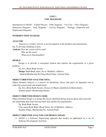
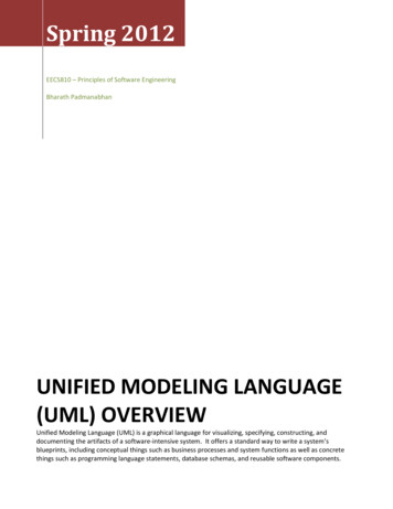
10UML Applied - Object Oriented Analysis and Design using the UMLChapter 2The UML within a Development ProcessThe UML as a NotationThe Three Amigos, when developing the UML, made a very clear decision to removeany process based issues from the language. This was because processes are verycontentious - what works for company A might be a disaster for company B. Adefence company requires much more documentation, quality and testing than (say)an e-commerce company. So the UML is a generic, broad language enabling the keyaspects of a software development to be captured on "paper".In other words, the UML is simply a language, a notation, a syntax, whatever youwant to call it. Crucially, it does not tell you how to develop software.To learn how to use the UML effectively, however, we will follow a simple processon this course, and try to understand how the UML helps at each stage. To start with,let's have a look at some common software processes.The Waterfall ModelFigure 2 - The traditional “Waterfall” model
11UML Applied - Object Oriented Analysis and Design using the UMLThe waterfall model prescribes that each stage must be complete before the next stagecan commence.This simplistic (and easy to manage) process begins to break down as the complexityand size of the project increases. The main problems are: Even large systems must be fully understood and analysed before progress can bemade to the design stage. The complexity increases, and becomes overwhelmingfor the developers. Risk is pushed forward. Major problems often emerge at the latter stages of theprocess – especially during system integration. Ironically, the cost to rectify errorsincrease exponentially as time progresses. On large projects, each stage will run for extremely long periods. A two-year longtesting stage is not necessarily a good recipe for staff retention!Figure 3 –Over time on the waterfall, both the risks and the cost to rectify errorsincreaseAlso, as the analysis phase is performed in a short burst at the outset of the project, werun a serious risk of failing to understand the customer’s requirements. Even if wefollow a rigid requirements management procedure and sign off requirements with thecustomer, the chances are that by the end of Design, Coding, Integration and Testing,the final product will not necessarily be what the customer wanted.Having said all the above, there is nothing wrong with a waterfall model, providingthe project is small enough. The definition of "small enough" is subjective, butessentially, if the project can be tackled by a small team of people, with each personable to understand every aspect of the system, and if the lifecycle is short (a few
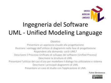
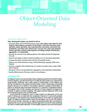
12UML Applied - Object Oriented Analysis and Design using the UMLmonths), then the waterfall is a valuable process. It is much better than chaotichacking!In summary, the waterfall model is easy to understand and simple to manage. But theadvantages of the model begin to break down once the complexity of the projectincreases.The Spiral ModelAn alternative approach is the spiral model. In this approach, we attack the project ina series of short lifecycles, each one ending with a release of executable software:Figure 4 - a spiral process. Here, the project has been divided into five phases,each phase building on the previous one and with a running release of softwareproduced at the end of each phaseWith this approach: The team are able to work on the entire lifecycle (Analysis, Design, Code, Test)rather than spending years on a single activityWe can receive early and regular feedback from the customer, and spot potentialproblems before going too far with developmentWe can attack risks up-front. Particularly risky iterations (for example, an iterationrequiring the implementation of new and untested technology) can be developedfirstThe scale and complexity of work can be discovered earlierChanges in technology can be incorporated more easilyA regular release of software improves moraleThe status of the project (eg – “how much of the system is complete”) can beassessed more accuratelyThe drawbacks of a spiral process are
13UML Applied - Object Oriented Analysis and Design using the UML The process is commonly associated with Rapid Application Development, whichis considered by many to be a hacker's charter. The process is much more difficult to manage. The Waterfall Model fits in closelywith classic project management techniques such as Gantt charts, but spiralprocesses require a different approach.To counteract the drawbacks of the spiral technical, let's look at a similar, but moreformal approach called an Iterative, Incremental Framework. Philippe Kruchten’s Whitepaper (reference [5], available from RationalSoftware’s website) explores the traps many managers are likely to face ontheir first iterative development.Iterative, Incremental FrameworksThe Iterative, Incremental Framework is a logical extension to the spiral model, but ismore formal and rigorous. We will be following an Iterative, Incremental Frameworkthrough the rest of this course.The framework is divided into four major phases: Inception; Elaboration;Construction and Transition. These phases are performed in sequence, but thephases must not be confused with the stages in the waterfall lifecycle. This sectiondescribes the phases and outlines the activities performed during each one.Figure 5 - the four phases of an Iterative, Incremental FrameworkInceptionThe inception phase is concerned with establishing the scope of the project andgenerally defining a vision for the project. For a small project, this phase could be asimple chat over coffee and an agreement to proceed; on larger projects, a morethorough inception is necessary. Possible deliverables from this phase are: A Vision DocumentAn initial exploration of the customer’s requirementsA first-cut project glossary (more on this later)A Business Case (including success criteria and a financial forecast, estimates ofthe Return on Investment, etc)An initial risk assessment
14 UML Applied - Object Oriented Analysis and Design using the UMLA project planWe’ll explore the inception phase in a little detail when we meet the case study inChapter 4.ElaborationThe purpose of elaboration is to analyse the problem, develop the project plan further,and eliminate the riskier areas of the project. By the end of the elaboration phase, weaim to have a general understanding of the entire project, even if it is not necessarily adeep understanding (that comes later, and in small, manageable chunks).Two of the UML models are often invaluable at this stage. The Use Case Model helpsus to understand the customer’s requirements, and we can also use the Class Diagramto explore the major concepts our customer understands. More on this shortly.ConstructionAt the construction phase, we build the product. This phase of the project is notcarried our in a linear fashion – rather, the product is built in the same fashion as thespiral model, by following a series of iterations. Each iteration is our old friend, thesimple waterfall.3 By keeping each iteration as short as possible, we aim to avoid thenasty problems associated with waterfalls.Figure 6 - The Construction Phase consists of a series of "mini waterfalls"3Note that at the inception and elaboration phases, prototypes can be built. These prototypes can bedeveloped in exactly the same way – as a series of mini waterfall iterations. However, for this course,we will keep the inception and elaboration phases simple and use the waterfalls for construction only.
15UML Applied - Object Oriented Analysis and Design using the UMLAt the end of as many iterations as possible, we will aim to have a running system(albeit, of course, a very limited system in the early stages). These iterations are calledIncrements, hence the name of the framework!TransitionThe final phase is concerned with moving the final product across to the customers.Typical activities in this phase include: Beta-releases for testing by the user communityFactory testing, or running the product in parallel with the legacy system that theproduct is replacingData takeon (ie converting existing databases across to new formats, importingdata, etc)Training the new usersMarketing, Distribution and SalesThe Transition phase should not be confused with the traditional test phase at the endof the waterfall model. At the start of Transition, a full, tested and running productshould be available for the users. As listed above, some projects may require a betatest stage, but the product should be pretty much complete before this phase happens.How Many Iterations? How Long Should They Be?A single iteration should typically last between 2 weeks and 2 months. Any more thantwo months leads to an increase in complexity and the inevitable “big bang”integration stage, where many software components have to be integrated for the firsttime.A bigger and more complex project should not automatically imply the need forlonger iterations – this will increase the level of complexity the developers need tohandle at any one time. Rather, a bigger project should require more iterations.Some factors that should influence the iteration length include: (see Larman [2],pp447-448). Early development cycles may need to be longer. This gives developers a chanceto perform exploratory work on untested or new technology, or to define theinfrastructure for the project.Novice staffParallel developments teamsDistributed (eg cross site) teams [note that Larman even includes in this categoryany team where the members are not all located on the same floor, even if they arein the same building!]To this list, I would also add that a high ceremony project will generally need longeriterations. A high ceremony project is one which might have to deliver a lot of projectdocumentation to the customer, or perhaps a project which must meet a lot of legalrequirements. A very good example would be any defence related project. In this case,the documentary work will extend the length of the iteration – but the amount of
16UML Applied - Object Oriented Analysis and Design using the UMLsoftware development tackled in the iteration should still be kept to a minimum toavoid our chief enemy, complexity overload.Time BoxingA radical approach to managing an iterative, incremental process is Time Boxing. Thisis a rigid approach which sets a fixed time period in which a particular iteration mustbe completed by.If an iteration is not complete by the end of the timebox, the iteration ends anyway.The crucial activity associated with timeboxing is the review at the end of iteration.The review must explore the reasons for any delays, and must reschedule anyunfinished work into future iterations.Larman (ref [2]) gives details on how to implement timeboxing. One of hisrecommendations is that the developers be responsible for (or at least, have a large sayin) setting which requirements are covered in each iteration, as they are the ones whowill have to meet the deadlines.Implementing timeboxing is difficult. It requires a culture of extreme disciplinethrough the entire project. It is extremely tempting to forgo the review and overstepthe timebox if the iteration is “99%” complete when the deadline arrives. Once aproject succumbs to temptation and one review is missed, the whole concept begins tofall apart. Many reviews are missed, future iterations planning becomes sloppy andchaos begins to set in.Some managers assume that timeboxing prevents slippage. It does not. If an iterationis not complete once the timebox has expired, then the unfinished work must bereallocated to later iterations, and the iteration plans are reworked – this could includeslipping the delivery date or adding more iterations. However, the benefits oftimeboxing are: The rigid structure enforces planning and replanning. Plans are not discarded oncethe project begins to slipIf timeboxes are enforced, there is less of a tendency for the project to descendinto chaos once problems emerge, as there is always a formal timebox review nottoo far awayIf panic sets in and developers start to furiously hack, the hacking is stemmedonce the review is heldEssentially, timeboxing allows the entire project to regularly “stand back” and takestock. It does not prevent slippage, and requires strong project management to work.Typical Project TimingsHow long should each of the four phases last? This is entirely up to individualprojects, but a loose guideline is 10% inception, 30% elaboration, 50% constructionand 10% transition.
17UML Applied - Object Oriented Analysis and Design using the UMLFigure 7 - Possible timings for each phase. This example shows the length of eachphase for a two year project.The Rational Unified ProcessThe Rational Unified Process (the RUP) is the most famous example of an Iterative,Incremental Lifecycle in use at the moment. The RUP was developed by the same"Three Amigos" that developed the UML, so the RUP is very complementary to theUML.Essentially, Rational appreciate that every project is different, with different needs.For example, for some projects, a tiny Inception Phase is appropriate, whereas fordefence projects, the Inception phase could last years.To this end, the RUP is tailorable, and enables each phase of the process to becustomised. The RUP also defines the roles of everyone on the project very carefully(in the shape of so-called Workers - again, these are tailorable to the project's needs).Rational Corp produce a product to help projects work with the RUP. Full details canbe found at www.rational.com. Essentially, the RUP project is an on-line, hypertextguide to every aspect of the RUP. Rational provide 30 day trials of the product.
18UML Applied - Object Oriented Analysis and Design using the UMLFigure 8 - Screenshot from RUP 2000 ( Rational Corp)The precise advantages and disadvantages of the RUP are beyond the scope of thiscourse. However, the core of the RUP, the Iterative, Incremental Lifecycle will befollowed throughout this course to illustrate the key aspects of the UML models. For more details on the RUP, Philippe Kruchten’s book The Rational UnifiedProcess– An Introduction (ref 1) covers the subject in detail.SummaryAn Iterative, Incremental Framework offers many benefits over traditional processes.The Framework is divided into four phases - Inception, Elaboration, Construction,Transition.Incremental development means to aim for running code at the end of as manyiterations as possible.Iterations can be timeboxed - a radical way of scheduling and reviewing iterations.The rest of this course will focus on the Framework, and how the UML supports thedeliverables of each phase in the Framework.
19UML Applied - Object Oriented Analysis and Design using the UMLChapter 3Object OrientationIn this chapter we will look at the concept of Object Orientation4 (OO). The UnifiedModelling Language has been designed to support Object Orientation, and we'll beintroducing Object Oriented concepts throughout this course. Before we begin lookingat the UML in depth, however, it is worth introducing OO and looking at theadvantages that OO can offer to Software Development.Structured ProgrammingFirst of all, let's examine (in very rough terms) how software systems are designedusing the Structured (sometimes called Functional) approach.In Structured Programming, the general method was to look at the problem, and thendesign a collection of functions that can carry out the required tasks. If thesefunctions are too large, then the functions are broken down until they are smallenough to handle and understand. This is a process known as functionaldecomposition.Most functions will require data of some kind to work on. The data in a functionalsystem was usually held in some kind of database (or possibly held in memory asglobal variables).As a simple example, consider a college management system. This system holds thedetails of every student and tutor in the college. In addition, the system also storesinformation about the courses available at the college, and tracks which student isfollowing which courses.A possible functional design would be to write the following functions:add student5enter for examcheck exam marksissue certificateexpel student4I'll use the phrase "Object Orientation" to denote Object Oriented Design and/or Object OrientedProgramming5I'm using underscores to highlight the fact that these functions are written in code.
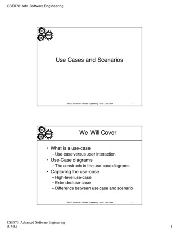
20UML Applied - Object Oriented Analysis and Design using the UMLWe would also need a data model to support these functions. We need to holdinformation about Students, Tutors, Exams and Courses, so we would design adatabase schema to hold this data.6Figure 9 - Simple Database Schema. The dotted lines indicate where one set ofdata is dependent on another. For example, each student is taught by severaltutors.Now, the functions we defined earlier are clearly going to be dependent on this set ofdata. For example, the "add student" function will need to modify the contents of"Students". The "issue certificate" function will need to access the Student data (toget details of the student requiring the certificate), and the function will also need toaccess the Exam data.6Note that throughout this chapter, I am not using a formal notation to describe the concepts
21UML Applied - Object Oriented Analysis and Design using the UMLThe following diagram is a sketch of all the functions, together with the data, andlines have been drawn where a dependency exists:Figure 10 - Plan of the functions, the data, and the dependenciesThe problem with this approach is that if the problem we are tackling becomes toocomplex, the system becomes harder and harder to maintain. Taking the exampleabove, what would happen if a requirement changes that leads to an alteration in theway in which Student data is handled?As an example, imagine our system is running perfectly well, but we realise thatstoring the Student's date of birth with a two digit year was a bad idea. The obvioussolution is to change the "Date of Birth" field in the Student table, from a two-digityear to a four-digit year.The serious problem with this change is that we might have caused unexpected sideeffects to occur. The Exam data, the Course data and the Tutors data all depend (insome way) on the Student data, so we might have broken some functionality with oursimple change. In addition, we might well have broken the add student,enter for exams, issue certificate and expel student functions. For example,add student will certainly not work anymore, as it will be expecting a two digit yearfor "date of birth" rather than four.So we have a large degree of potential knock-on problems. What is far, far worse isthat in our program code, we cannot easily see what these dependencies actually are.How many times have you changed a line of code in all innocence, without realisingthat you've inadvertently broken apparently unrelated functionality?The costly Year 2000 problem (The Millennium Bug) was caused by exactly thisproblem. Even though the fix should be simple (make every year occupy four digits
22UML Applied - Object Oriented Analysis and Design using the UMLinstead of two), the potential impacts of these minor changes had to be investigated indetail.7The Object Orientated ApproachOO tries to lessen the impact of this problem by simply combining related data andfunctions into the same module.Looking at Figure 10 above, it is apparent that the data and functions are related. Forexample, the add student and expel student functions are clearly very closely relatedto the Student data.The following figure shows the full grouping of the related data and functions, in theform of modules:Figure 11 - Related data and functions placed in modulesA couple of points to note about this new modular system of programming: More than one instance of a single module can exist when the program is running.In the college system, there would be an instance of "Student" for every studentthat belongs to the college. Each instance would have its own values for the data(certainly each would have a different name). Modules can "talk" to other modules by calling each other's functions. Forexample, when the "add" function is called in Student, a new instance of theStudent module would be created, and then the "add attendee" function would becalled from the appropriate instances of the "Course" module.7This doesn't mean that I am implying that all non-OO Cobol systems are a load of rubbish, by theway. There is nothing wrong with structured programming. My suggestion in this chapter is that OOprovides a method of building more robust software as our systems get larger and more complex.
23UML Applied - Object Oriented Analysis and Design using the UMLEncapsulationCrucially, only the instance that owns an item of data is allowed to modify or read it.So for example, an instance of the Tutor module cannot update or read the "age" datainside the Student module.This concept is called Encapsulation, and enables the structure of the system to be farmore robust, and avoid the situation as described previously, where a small change toa data member can lead to rippling changes.With Encapsulation, the programmer of (say) the Student module can safely makechanges to the data in the module, and rest assured that no other
In Java 119 In C 120 The UML Component Model 120 Ada Components 121 Summary 121 BIBLIOGRAPHY 123 . 7 UML Applied - Object Oriented Analysis and Design using the UML Chapter 1 An Introduction to the UML What is the UML? The Unified Modelling Language, or the UML, is a graphical modelling language that