Transcription
SC900Service ManualAdvance Model SC900-32CEnglish07/2016 Form No. 56043175
Service Manual – SC900ContentsContents03 - General Information . . . . . . . . . . . . . . . . . . . . . . . . . . . . . . . . . . . 5General Machine Description . . . . . . . . . . . . . . . . . . . . . . . . . . . . . . . . . 5Service Manual Purpose and Application . . . . . . . . . . . . . . . . . . . . . . . . . . 5Other Reference Manuals and Information Sources . . . . . . . . . . . . . . . . . . . . . 5Parts And Service . . . . . . . . . . . . . . . . . . . . . . . . . . . . . . . . . . . . . . . 5Diagnostic and Service Tools . . . . . . . . . . . . . . . . . . . . . . . . . . . . . . . . . 5Conventions . . . . . . . . . . . . . . . . . . . . . . . . . . . . . . . . . . . . . . . . . . 5Modifications . . . . . . . . . . . . . . . . . . . . . . . . . . . . . . . . . . . . . . . . . . 6Nameplate . . . . . . . . . . . . . . . . . . . . . . . . . . . . . . . . . . . . . . . . . . . 6Safety . . . . . . . . . . . . . . . . . . . . . . . . . . . . . . . . . . . . . . . . . . . . . 7Symbols . . . . . . . . . . . . . . . . . . . . . . . . . . . . . . . . . . . . . . . . . . 7General Safety Instructions . . . . . . . . . . . . . . . . . . . . . . . . . . . . . . . 7Property Damage Messages . . . . . . . . . . . . . . . . . . . . . . . . . . . . . 8Lifting or Transporting the Machine . . . . . . . . . . . . . . . . . . . . . . . . . . . . . 9Technical Specifications . . . . . . . . . . . . . . . . . . . . . . . . . . . . . . . . . . . 10Know Your Machine — Major components: . . . . . . . . . . . . . . . . . . . . . . . . 11Maintenance Schedule . . . . . . . . . . . . . . . . . . . . . . . . . . . . . . . . . . . 12Lubricating the Machine . . . . . . . . . . . . . . . . . . . . . . . . . . . . . . . . 1214 - Wheel System, Non-Traction . . . . . . . . . . . . . . . . . . . . . . . . . . . . . . 13Functional Description . . . . . . . . . . . . . . . . . . . . . . . . . . . . . . . . . . . 13Removal and Installation . . . . . . . . . . . . . . . . . . . . . . . . . . . . . . . . . . 1320 - Wheel System, Traction . . . . . . . . . . . . . . . . . . . . . . . . . . . . . . . .Functional Description . . . . . . . . . . . . . . . . . . . . . . . . . . . . . . . . . . .Forward and Reverse Switches . . . . . . . . . . . . . . . . . . . . . . . . . . . . .Speed Limiting Potentiometer . . . . . . . . . . . . . . . . . . . . . . . . . . . . .Drive Motor PWM Function . . . . . . . . . . . . . . . . . . . . . . . . . . . . . .Drive Controller . . . . . . . . . . . . . . . . . . . . . . . . . . . . . . . . . . . . .Circuit Description (Idle) . . . . . . . . . . . . . . . . . . . . . . . . . . . . . . . .Circuit Description (Driving) . . . . . . . . . . . . . . . . . . . . . . . . . . . . . .Troubleshooting . . . . . . . . . . . . . . . . . . . . . . . . . . . . . . . . . . . . . . .Error Codes . . . . . . . . . . . . . . . . . . . . . . . . . . . . . . . . . . . . . . .Removal and Installation . . . . . . . . . . . . . . . . . . . . . . . . . . . . . . . . . .Drive Controller . . . . . . . . . . . . . . . . . . . . . . . . . . . . . . . . . . . . .Follow-up Testing . . . . . . . . . . . . . . . . . . . . . . . . . . . . . . . . . .Wheels . . . . . . . . . . . . . . . . . . . . . . . . . . . . . . . . . . . . . . . . . .Drive Motor . . . . . . . . . . . . . . . . . . . . . . . . . . . . . . . . . . . . . . .Motor Brushes . . . . . . . . . . . . . . . . . . . . . . . . . . . . . . . . . . . . . .Transaxle . . . . . . . . . . . . . . . . . . . . . . . . . . . . . . . . . . . . . . . .Specifications . . . . . . . . . . . . . . . . . . . . . . . . . . . . . . . . . . . . . . . .Shop Measurements . . . . . . . . . . . . . . . . . . . . . . . . . . . . . . . . . . .Special Tools . . . . . . . . . . . . . . . . . . . . . . . . . . . . . . . . . . . . . . . . .Curtis Programmer . . . . . . . . . . . . . . . . . . . . . . . . . . . . . . . . . . .14141414151516171818202020212223242626272724 - Electrical System . . . . . . . . . . . . . . . . . . . . . . . . . . . . . . . . . . . . 28Functional Description . . . . . . . . . . . . . . . . . . . . . . . . . . . . . . . . . . . 28Troubleshooting . . . . . . . . . . . . . . . . . . . . . . . . . . . . . . . . . . . . . . . 30Battery Testing . . . . . . . . . . . . . . . . . . . . . . . . . . . . . . . . . . . . . 31Maintenance and Adjustment . . . . . . . . . . . . . . . . . . . . . . . . . . . . . . . . 32Setting Onboard Charger Battery Profile . . . . . . . . . . . . . . . . . . . . . . . 32Removal and Installation . . . . . . . . . . . . . . . . . . . . . . . . . . . . . . . . . . 33Electrical Bay Cover . . . . . . . . . . . . . . . . . . . . . . . . . . . . . . . . . . 33Squeegee and Brush Switches . . . . . . . . . . . . . . . . . . . . . . . . . . . . . 33ii
Service Manual – SC900Drive Handle . . . . . . . . . . . . . . . . . . . . . . . . . . . . . . . . . . . . . .Switches and Harness . . . . . . . . . . . . . . . . . . . . . . . . . . . . . . .Hour Meter . . . . . . . . . . . . . . . . . . . . . . . . . . . . . . . . . . . . .Drive Handle Reassembly Notes . . . . . . . . . . . . . . . . . . . . . . . . . .Batteries . . . . . . . . . . . . . . . . . . . . . . . . . . . . . . . . . . . . . . . . .Specifications . . . . . . . . . . . . . . . . . . . . . . . . . . . . . . . . . . . . . . . .Connector Pinouts . . . . . . . . . . . . . . . . . . . . . . . . . . . . . . . . . . . .TrackClean Connector . . . . . . . . . . . . . . . . . . . . . . . . . . . . . . .EcoFlex Connector . . . . . . . . . . . . . . . . . . . . . . . . . . . . . . . . .Operator’s Handle Connector . . . . . . . . . . . . . . . . . . . . . . . . . . .Drive Controller Connector . . . . . . . . . . . . . . . . . . . . . . . . . . . . .Wiring Diagram . . . . . . . . . . . . . . . . . . . . . . . . . . . . . . . . . . . . .Harness Diagram . . . . . . . . . . . . . . . . . . . . . . . . . . . . . . . . . . . .Contents3435363638393939393940414230 - Solution System . . . . . . . . . . . . . . . . . . . . . . . . . . . . . . . . . . . . . 43Functional Description . . . . . . . . . . . . . . . . . . . . . . . . . . . . . . . . . . . 43Non-Detergent Models . . . . . . . . . . . . . . . . . . . . . . . . . . . . . . . . . 43Detergent Models . . . . . . . . . . . . . . . . . . . . . . . . . . . . . . . . . . . . 44Detergent Pump . . . . . . . . . . . . . . . . . . . . . . . . . . . . . . . . . . . . . 44Troubleshooting . . . . . . . . . . . . . . . . . . . . . . . . . . . . . . . . . . . . . . . 45Scrub System, General . . . . . . . . . . . . . . . . . . . . . . . . . . . . . . . . . 45No Solution Flow . . . . . . . . . . . . . . . . . . . . . . . . . . . . . . . . . . . . 46No EcoFlex Detergent Flow . . . . . . . . . . . . . . . . . . . . . . . . . . . . . . . 46Removal and Installation . . . . . . . . . . . . . . . . . . . . . . . . . . . . . . . . . . 47Scrub Skirt . . . . . . . . . . . . . . . . . . . . . . . . . . . . . . . . . . . . . . . 47Solution Solenoid . . . . . . . . . . . . . . . . . . . . . . . . . . . . . . . . . . . . 47Solution Filter . . . . . . . . . . . . . . . . . . . . . . . . . . . . . . . . . . . . . . 48Solution Control Panel and Cable . . . . . . . . . . . . . . . . . . . . . . . . . . . 49EcoFlex Control Panel . . . . . . . . . . . . . . . . . . . . . . . . . . . . . . . . . 50Specifications . . . . . . . . . . . . . . . . . . . . . . . . . . . . . . . . . . . . . . . . 5034 - Scrub System, Disc . . . . . . . . . . . . . . . . . . . . . . . . . . . . . . . . . . .Functional Description . . . . . . . . . . . . . . . . . . . . . . . . . . . . . . . . . . .Circuit Overview . . . . . . . . . . . . . . . . . . . . . . . . . . . . . . . . . . . .Troubleshooting . . . . . . . . . . . . . . . . . . . . . . . . . . . . . . . . . . . . . . .Scrub System, General . . . . . . . . . . . . . . . . . . . . . . . . . . . . . . . . .One Brush Not Working . . . . . . . . . . . . . . . . . . . . . . . . . . . . . . . .Both Brush Motors Not Working . . . . . . . . . . . . . . . . . . . . . . . . . . . .Removal and Installation . . . . . . . . . . . . . . . . . . . . . . . . . . . . . . . . . .Scrub Skirt . . . . . . . . . . . . . . . . . . . . . . . . . . . . . . . . . . . . . . .Scrub Brush Motor . . . . . . . . . . . . . . . . . . . . . . . . . . . . . . . . . . .Brush Motor Brushes . . . . . . . . . . . . . . . . . . . . . . . . . . . . . . . . . .Specifications . . . . . . . . . . . . . . . . . . . . . . . . . . . . . . . . . . . . . . . .51515253535454555555565834 - Scrub System, Cylindrical . . . . . . . . . . . . . . . . . . . . . . . . . . . . . . . 59Functional Description . . . . . . . . . . . . . . . . . . . . . . . . . . . . . . . . . . . 59Circuit Overview . . . . . . . . . . . . . . . . . . . . . . . . . . . . . . . . . . . . 60Troubleshooting . . . . . . . . . . . . . . . . . . . . . . . . . . . . . . . . . . . . . . . 61Scrub System, General . . . . . . . . . . . . . . . . . . . . . . . . . . . . . . . . . 61One Brush Not Working . . . . . . . . . . . . . . . . . . . . . . . . . . . . . . . . 62Both Brush Motors Not Working . . . . . . . . . . . . . . . . . . . . . . . . . . . . 62Removal and Installation . . . . . . . . . . . . . . . . . . . . . . . . . . . . . . . . . . 63Scrub Skirt . . . . . . . . . . . . . . . . . . . . . . . . . . . . . . . . . . . . . . . 63Scrub Brush Motor . . . . . . . . . . . . . . . . . . . . . . . . . . . . . . . . . . . 63Brush Motor Brushes . . . . . . . . . . . . . . . . . . . . . . . . . . . . . . . . . . 64Specifications . . . . . . . . . . . . . . . . . . . . . . . . . . . . . . . . . . . . . . . . 67iii
Service Manual – SC900Contents38 - Squeegee System . . . . . . . . . . . . . . . . . . . . . . . . . . . . . . . . . . . . 68Functional Description . . . . . . . . . . . . . . . . . . . . . . . . . . . . . . . . . . . 68Squeegee . . . . . . . . . . . . . . . . . . . . . . . . . . . . . . . . . . . . . . . . . 68Maintenance and Adjustment . . . . . . . . . . . . . . . . . . . . . . . . . . . . . . . . 69Squeegee Blade Cleaning and Inspection . . . . . . . . . . . . . . . . . . . . . . . 69Squeegee Tilt Adjustment . . . . . . . . . . . . . . . . . . . . . . . . . . . . . . . 69Removal and Installation . . . . . . . . . . . . . . . . . . . . . . . . . . . . . . . . . . 70Squeegee Blade Replacement . . . . . . . . . . . . . . . . . . . . . . . . . . . . . . 7040-Recovery System . . . . . . . . . . . . . . . . . . . . . . . . . . . . . . . . . . . . . 71Functional Description . . . . . . . . . . . . . . . . . . . . . . . . . . . . . . . . . . . 71Vacuum Motor and Recovery Tank . . . . . . . . . . . . . . . . . . . . . . . . . . . 71Circuit Overview . . . . . . . . . . . . . . . . . . . . . . . . . . . . . . . . . . . . 72Troubleshooting . . . . . . . . . . . . . . . . . . . . . . . . . . . . . . . . . . . . . . . 72No Vacuum Motor . . . . . . . . . . . . . . . . . . . . . . . . . . . . . . . . . . . . 72Poor Suction . . . . . . . . . . . . . . . . . . . . . . . . . . . . . . . . . . . . . . . 72Vacuum Suction Test . . . . . . . . . . . . . . . . . . . . . . . . . . . . . . . . . . 73Removal and Installation . . . . . . . . . . . . . . . . . . . . . . . . . . . . . . . . . . 74Vacuum Motor . . . . . . . . . . . . . . . . . . . . . . . . . . . . . . . . . . . . . . 74Vacuum Motor Brushes . . . . . . . . . . . . . . . . . . . . . . . . . . . . . . . . . 75Specifications . . . . . . . . . . . . . . . . . . . . . . . . . . . . . . . . . . . . . . . . 76Special Tools . . . . . . . . . . . . . . . . . . . . . . . . . . . . . . . . . . . . . . . . . 7690 - Options and Accessories . . . . . . . . . . . . . . . . . . . . . . . . . . . . . . . . 77Onboard Charger . . . . . . . . . . . . . . . . . . . . . . . . . . . . . . . . . . . . . . 77TrackClean . . . . . . . . . . . . . . . . . . . . . . . . . . . . . . . . . . . . . . . . . . 77EcoFlex . . . . . . . . . . . . . . . . . . . . . . . . . . . . . . . . . . . . . . . . . . . . 77Battery Watering . . . . . . . . . . . . . . . . . . . . . . . . . . . . . . . . . . . . . . 77iv
Service Manual – SC900503 - General InformationGeneral Machine DescriptionThe SC900 machine is a battery-powered, walk-behind, self-propelled commercial floor scrubbing machinewith either a disc or cylindrical scrub system, and suitable for use in hotels, schools, hospitals, factories,shops, offices, rental businesses and similar applications. The SC900-28D has a 28" disc deck. The SC90034D has a 34" disc deck. The SC900-32C has a 32" cylindrical deck.The machine is powered by six, 6-volt batteries connected in series, to provide 36 VDC to the motors andcontrols.Service Manual Purpose and ApplicationThis Service Manual is a resource for professional service technicians. It provides information forunderstanding how the machine operates, where components are located, basic troubleshooting,maintenance, and mechanical service operations.Other Reference Manuals and Information SourcesDocument NameDocumentNumberDocument TypeInstructions for Use56091183Operator’s ManualParts List56042634Parts ListParts And ServiceRepairs should be performed by an Authorized Advance Service Center that employs factory-trained servicepersonnel and maintains an inventory of Advance original replacement parts and accessories.Call the Advance Dealer named below for repair parts or service. Please specify the Model Number (same asthe Part Number) and Serial Number when discussing your machine.Diagnostic and Service ToolsIn addition to a full set of metric and standard tools, the following items are required in order to successfullyand quickly perform troubleshooting and repair of Advance commercial floor cleaning equipment. Digital voltmeter (DVM) with DC current clamp Hydrometer Battery load tester for checking batteries Set of torque wrenchesThese tools are also available from Nilfisk-Advance, Inc.: Curtis 1311 hand held programmer, p/n 56409441, Vacuum water lift gauge, p/n 56205281.ConventionsAll references to right, left, front and rear in this manual are as seen from the Operator’s position.
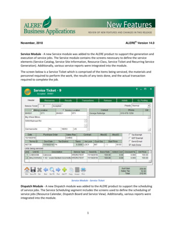
Service Manual – SC90003 - General InformationModificationsModifications and additions to the cleaning machine which affect capacity and safe operation shall notbe performed by the customer or user without prior written approval from Nilfisk, Inc. Unapprovedmodifications will void the machine warranty and make the customer liable for any resulting accidents.NameplateThe nameplate contains importantidentification information which will beneeded when ordering parts: The ModelNumber (Part No.) and Serial Number of themachine are shown on the Nameplate locatedon the inside of the battery compartment.This information is needed when orderingrepair parts for the machine.6
Service Manual – SC90003 - General InformationSafetySymbolsIt is important for you to read and understand this manual. The information it contains relates to protectingyour safety and preventing problems. The symbols below are used to help you recognize this information.DANGER: Indicates a potentially hazardous situation which, if not avoided, will result in death orserious injury.WARNING: Indicates a potentially hazardous situation which, if not avoided, could result in deathor serious injury.CAUTION: Indicates a potentially hazardous situation which, if not avoided, could result in minoror moderate injury.Note: Indicates an important informational message.General Safety InstructionsThese safety instructions are included to warn you of potential bodily injury or property damage.CAUTION: Read and understand all safety warnings and instructions. Failure to follow thewarnings and instructions may result in electric shock, fire, and/or serious injury. To avoid personal injury, this machine should be used only by properly trained andauthorized persons. Do not operate the machine near toxic, dangerous, flammable and/or explosivematerials. This machine is not suitable for collecting dangerous or hazardousmaterials. In case of fire, use a powder fire extinguisher, not a water-based extinguisher. Do not use on surfaces having a gradient exceeding that marked on the machine.While on ramps or inclines, avoid sudden stops when loaded. Avoid abrupt sharpturns. Disconnect the power source and/or batteries before servicing electrical components Never work under a machine without safety blocks or stands to support the machine. Do not dispense flammable cleaning agents, operate the machine on or near theseagents, or operate in areas where flammable liquids exist. When using floor cleaning detergents, follow all safety and handling instructions of therespective manufacturer. Battery charging may produce highly explosive hydrogen gas. Charge the batteriesonly in well-ventilated areas and away from ignition sources or open flames. When operating this machine, ensure that third parties, particularly children, are notendangered. Take precautions to prevent hair, jewelry, or loose clothing from becoming caught inmoving parts.7
Service Manual – SC90003 - General InformationProperty Damage Messages Storage and operation temperature must be above 32 F (0 C) and a humidity between30% and 95%, non-condensing. Before use, all doors and hoods should be properly latched. This machine is not approved for use on public paths or roads. This machine is only approved for hard surface use. Use brushes and pads supplied with the machine or those specified in the UserManual. Using other brushes or pads could reduce safety. Do not wash the machine with direct or pressurised water jets, or with corrosivesubstances. Do not allow the brush/pad to operate while the machine is stationary to avoiddamaging the floor. Use only factory authorized parts and accessories. This machine must be properly disposed of in accordance with local laws andregulations.8
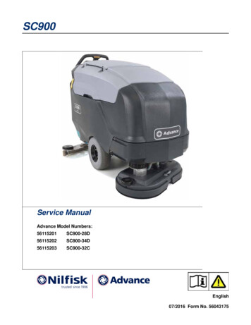
Service Manual – SC90003 - General InformationLifting or Transporting the MachineCAUTION: Never work under a machine without safety stands or blocks to support the machine. Drain the recovery and solution tanks to prevent sloshing water from unbalancing themachine. Lift only from the subframe of the machine, as shown below. Secure the machine to the transport using the tie down points shown below.The actual procedure for transporting the machine will vary depending on the mode of transport. Followthese general guidelines as applicable to the situation. Remove the squeegee from the machine. This is required to access the rear hold down points and alsoprotects the squeegee during loading, unloading, and transport. If transport will occur below freezing temperatures, place a small amount of environmentally friendlyantifreeze in the recovery tank, solution tank, and solution lines. Make sure all doors, panels, and covers are secure. Secure the machine to the transport using both front and both rear tie down points.Tie DownsTie Downs &Rear Lift Points9
Service Manual – SC90003 - General InformationTechnical SpecificationsModelModel No.SC900 28DSC900 34DSC900 32C561152015611520256115203Voltage, Batteries36V (6 x 6V)Battery Capacity310 AhProtection GradenaS P L IEC 60335-2-72: 2002 Amend. 1:2005,ISO 1120166.4 dB(A)/20µPaS P L – KpA (IEC 60335-2-72, ISO 11201)UncertaintyVibrations at the Hand Controls (ISO 5349-1)66.4 dB(A)/20µPa68.8 dB(A)/20µPa 70 dB(A)0.510 m/s2Vibrations at the Hand Controls (ISO 5349-1)Uncertainty0.381 m/s20.476 m/s2 2.5 m/s2Maximum Wheel Floor Loading (right front)147 psi / 1.0 N/mm2 128 psi / 0.89 N/mm2 155 psi / 1.1 N/mm2Maximum Wheel Floor Loading (left front)107 psi / 0.74 N/mm2 132 psi / 1.0 N/mm2 128 psi / 0.88 N/mm2Maximum Wheel Floor Loading (right rear)205 psi / 1.4 N/mm2 432 psi / 3.0 N/mm2 245 psi / 1.7 N/mm2Maximum Wheel Floor Loading (left rear)521 psi / 5.6 N/mm2 640 psi / 4.4 N/mm2 416 psi / 2.9 N/mm2Machine Width (chasis)30.3” / 77.0 cm30.3” / 77.0 cm30.6” / 77.7 cmMachine Width with Squeegee41.8” / 106.2 cm41.8” / 106.2 cm41.8” / 106.2 cmMachine HeightMachineLength44.8” / 113.8 cm65.4” / 166 cmSolution Tank CapacityScrub brush size (2 per machine)Scrub Brush Speed ( Left / Right )63.1” / 160.3 cm29.5 Gal / 111.7 LRecovery Tank CapacityBattery Compartment Size (approximate)67.4” / 171 cm32 Gal / 121 LHeight (maximum)Width (maximum)Length (maximum)15 in / 38 cm26 in / 66 cm27.5 in / 70 cmØ 14 inch / 35.5 cm Ø 17 inch / 43.1 cm5.5 x 31 Inch13.9 x 78.7 cm255 / 259 RPM256 / 260 RPM820 / 735 RPMCleaning Path Width (scrubbing path)28 inch / 71.1 cm34 inch / 86.3 cm31 inch / 78.7 cmGross Weight*1189 Lbs. 539,3kg1205 Lbs. 546,8kg1235 Lbs. 560,2kg942 lbs / 427 kg979 lbs / 444 kg1006 lbs / 456 kgTransport Weight**Vacuum Motor Size710 watts max HP 0.95Drive Motor Size.5 HPBrush Motor Size0.75 HPMaximum Scrub Speed3.2Maximum Transport Speed3.2Gradeability Transport16% (9.1 )Gradeability Cleaning8.3% (4.75 )*Gross Weight: Standard machine without options, full solution tank and empty recovery tank, with removablescrub brushes and 310 AH batteries installed.**Transportation Weight: Standard machine without options, empty solution and recovery tanks, with batteriesinstalled and no operator.10
Service Manual – SC90003 - General InformationKnow Your Machine — Major olutionTankDisk DeckCylindricalDeckChassis& DriveSqueegee11
Service Manual – SC90003 - General InformationMaintenance ScheduleMaintenance intervals given are for average operating conditions. Machines used in severe operationalenvironments may require service more often.IntervalMaintenance ItemDailyCharge Batteries Check/Clean Tanks & Hoses Check/Clean/Rotate the Brushes/Pads Check/Clean the Squeegee Check/Clean Vacuum Shut-Off Float Clean Hopper on Cylindrical System Empty/Clean Debris Catch Tray in Recovery Tank WeeklyCheck Battery Cell Water Level (does not apply to gel cell batteries) Inspect Scrub Housing Skirts Inspect and Clean Solution Filter Clean Solution Manifolds on Cylindrical System Purge Detergent System (AXP and EcoFlex) MonthlyYearly Lubricate the MachineCheck Vacuum Motor Carbon Brushes300 hoursCheck Brush Motor Carbon Brushes500 hoursCheck Drive Motor Carbon Brushes500 hoursNote: See the individual machine system sections for maintenance information.Carbon Brush Notes: The original (new) length of each carbon brush is 1” (25.4mm) on brush and wheel drive motors. All motors: Replace carbon brushes when shorter than 3/8” (9.5mm) to obtain the same motorefficiency as new brushes.Lubricating the MachineDCDOnce a month, apply light machine oil tolubricate the: General Pivot Points for the SqueegeeLinkage (A).B Squeegee end wheels (B).A Scrub deck bumper wheel (C). General Pivot Points for the BrushLinkage (D).EOnce per quarter, Grease the followingB Rear Caster Wheel Swivels (E).12
Service Manual – SC9001314 - Wheel System, Non-TractionFunctional DescriptionThe SC900 machine is propelled by the drivewheels. The rear caster wheels add stability andease of turning.Removal and InstallationCasterWheelsWARNING: Never work under machine without safety stands orblocking to support the machine.1. To reduce the weight of the machine, drain both the recovery and solution tanks.2. Raise the rear of the machine and place blocking under the rear lifting points.3. Remove the four screws and washers that secure the caster to the chassis, and remove the caster.
Service Manual – SC9001420 - Wheel System, TractionFunctional DescriptionThe SC900 machine is driven by an electricallypowered transaxle. The transaxle is an opendifferential powered by a 1/2 hp, permanentmagnet, 36V motor. A Curtis 1228 solidstate speed controller regulates the speedand direction of the wheel drive motor. Themotor speed controller is located in theelectrical compartment of the battery bay.The potentiometer (R1) on the control handle,controls the speed setting of the machine. Thecontrol handle also contains two forward and onereverse drive buttons.Forward and Reverse SwitchesControlHandleTransaxleFunctionally, there are two forward and onereverse buttons on the control handle. However,electrically, there are actually three “Go”switches and a single “Reverse” switch. Thedistinction is because the reverse button actuallycontains two switches internally, where oneswitch is reverse and the second switch is a thirdGo switch. The three Go switches are in parallel, so they all act the same.The three Go switches signal the drive controller to move, and the reverse switch just changes its direction.The reverse switch by itself will not make the machine move.The incoming side of the Go switches is connected to the Pot-Lo output from the drive controller, which is at0 volts. The output side of the switches is connected to the throttle input of the drive controller, and also thelow side of the speed limit potentiometer.The incoming side of the reverse switch is connected to the key switch output. When the key switch is turnedon, the reverse switch receives 36 volts. When the reverse switch is also closed, this 36 volts is provided tothe “Reverse” input of the drive controller, which signals the controller that when it operates, it should be inthe reverse direction.Speed Limiting PotentiometerThe speed limiting potentiometer (R1 pot) is a 3-wire variable resistor connected to the Speed Limit inputof the drive controller. This pot sets the upper speed limit of the controller so that when any Go switch iscl
Service Manual. Advance Model Numbers: 56115201 SC900-28D 56115202 SC900-34D 56115203 SC900-32C English. Service Manual - SC900. . and solution lines Make sure all doors, panels, and covers are secure Secure the machine to the transport using both front and both rear tie down points : Tie Downs & Rear Lift Points Tie Downs: