Transcription
Pr oc ess Contr olsProcess ControlsACHIEVING OPTIMAL MOLDINGRESULTS WITH INJECTION PROCESSCONTROLLERS, BUTTON SENSORSAND SLIDE SENSORSBackTable of ContentsIndex
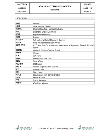
Process Controls62Portable Cavity and Hydraulic Pressure Monitor and Controller COMPACT AND SELF CONTAINED PROVIDES DIGITAL DISPLAY READOUT OF HYDRAULIC ANDCAVITY PRESSURES PROVIDES AMPLIFIED OUTPUT OF PRESSURE SIGNAL 1 AMP RELAY OUTPUT FOR CONTROL OF BOOSTER PUMP CUTOUTProcess Controls Portable Cavity and Hydraulic Pressure Monitor and Controller PROVIDES EASY CALIBRATION OF D-M-E CONSTANTCALIBRATION SENSORSThe IPC-01-01 Injection Process Controller is a portable devicethat provides an inexpensive means of controlling peak plasticspressure in the mold. Peak pressure control is accomplishedusing a mold pressure sensor and a single setpoint to controlfilling and packing of the mold. By closely monitoring andcontrolling cavity pressure the user will reduce cycle time,reject rates and plastics usage. The controller operates thebooster pump for the absolute minimum time required to filland pack the cavities, significantly reducing electrical powerconsumption.The IPC-01-01 controller uses a technique known as DynamicPressure Control (DPC). DPC maintains a more constant peakcavity pressure than machine timers and limit switches,regardless of plastic viscosity changes. This is accomplishedby switching from High Volume (Fill) to Low Volume (Hold)injection at a predetermined cavity pressure.Because of a direct correlation between peak cavity pressureand part weight (and therefore part size), accurate control ofpeak cavity pressure means more consistent part production.Because part weight range can be reduced by using DPC, theaverage part weight can be reduced without occurrences ofshort shots. This translates into potential reduction in materialusage. Increased repeatability in part weight also means lessscrap as a result of short shots, over packed and flashed parts.Reducing these occurrences can also reduce associated wearand damage to tooling.The IPC offers the three most requested features in a pressuremonitor/controller:1. Display of the pressure reading, including the peak pressurethat occurred.2. Amplification of the pressure signal for use by other equipment.3. A relay contact set for direct control of the moldingmachine’s booster pump cutoff function.The IPC uses an injection signal or other switch closure to armthe holding of the peek pressure that occurred during the shot.The peak pressure reading is held until the end of the injectionsequence.A connector on the rear of the IPC provides the amplifiedpressure signal. A zero to 1, 2, 5, or 10 VDC (or 4 to 20 mA DC)signal directly corresponds to a zero to 20.000 PSI pressure.This signal can be routed to strip chart recorders, plant wideU.S. 800-626-6653Nmonitors or other equipment. The signal can also be input intomolding machines offering closed loop pressure control butthat lack the necessary amplifiers for the sensing equipment.The IPC offers a one amp, form C (normally open, normallyclosed) relay contact set for direct control of the machine’sbooster cutout function. The relay contacts are also gold platedfor switching of low level signals such as the potentiometersused to set the machine’s injection velocity. Many controlrelays are not capable of switching such sensitive signals.The relay contacts carry a voltage rating of up to 120 VAC.The IPC is designed for use with D-M-E’s Constant Calibrationsensors but can be used with other manufacturers strain gagebased sensors as well.FRONT PANEL CONTROLS AND INDICATORSThe IPC offers quick easy calibration of pressure sensorsvia front panel adjustments. Calibration is quicklyperformed by pressing a push button and then adjustingthe calibration setting.A rotary switch allows for rapid selection of the pressuresensor and ejector pin size. A second rotary switch allowsfor selecting what is displayed: The pressure signal withpeak hold, the pressure signal without peak hold or theDPC pressure setpoint.A DPC light illuminates when the mold (or hydraulic)pressure reaches setpoint. This is an indication that theIPC’s control relay has activated.A toggle switch allows the user to override the controlfunction while allowing for continued monitoring of pressures.A high accuracy ten-turn potentiometer allows for input ofthe pressure setpoint for booster cutout.A three and one-half digit display allows for direct readoutof pressures up to 19,990 PSI. This is displayed as pressure(times 10) for mold pressure.A UL, CSA, VDE approved power switch allows the user toturn the IPC on and off from the front panel. Internal fuses(not shown) protect the unit from both sides of the AC linevoltage. While the standard unit (IPC-01-01) is constructedfor 120 VAC use, an optional IPC-01-02 is available. The unitis easily converted between 120 and 240 VAC operation.The 120 VAC unit comes with a standard wall outlet plug.Canada 800-387-6600Nwww.dme.net
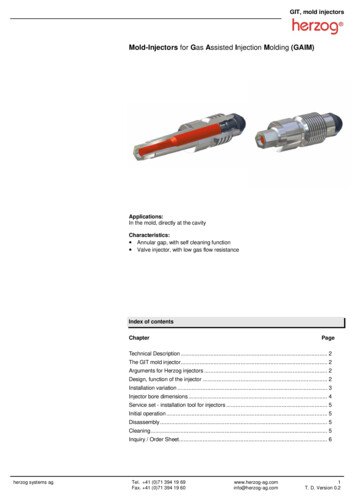
Process Controls63Portable Cavity and Hydraulic Pressure Monitor and ControllerREAR PANEL (LEFT TO RIGHT) Analog Output: is a standard 1/4 inch stereo headphone jack thatoutputs an amplified pressure signal of zero to 1, 2, 5 or 10 VDC (or 4 to20 mA DC) corresponding to zero to 20,000 PSI.D-M-E Sensor: accepts a D-M-E slide, or button sensor or relatedextension cable. Also accepts other sensors via a conversion cable.Machine Interface: provides the injection forward and booster cutoutwiring connections to the molding machine.Power Input: provides 120 VAC (standard) or 240 VAC (optional)power for operation.ORDERING INFORMATIONAccuracy:Analog output and digital display: / 1%full scaleSetpoint: 0.8% of full scaleCONTROLLERIncludes 19 foot integral power cable, mating control and analog outputconnectors and two spare fuses. Pressure sensors and extension cablesmust be ordered separately.Repeatability:Analog output and digital display: / 0.5%full scaleSetpoint: 0-25% of full scaleRecorder Output:Proportional to cavity pressure.Zero to 1, 2, 5 or 10 VDC (or 4 to 20 mA DC)corresponds to zero to 20,000 PSIZero to 20,000 PSITemperature Range:50 to 130 FPower Required:115 VAC (105-125), 50-60HzZero Drift, Analog Out:Long Term: 0.1%/month, with temperature0.1%/ FControl Relay:1 amp, form C, 0-120 VAC, VDCInjection Forward In:normally open contact closure, less than10 milliampsDimensions:7.2” wide, 2.7” high, 8.6” deepCatalog Numbers: IPC-01-01 (120 VAC standard)IPC-01-02 (240 VAC optional)Fuse Requirement: (2) ABC-1 fusesSLIDE MOLD PRESSURE SENSORSCatalog Numbers: SS-405CSS-406C(500 pound)*(2000 pound)*BUTTON MOLD PRESSURE SENSORSCatalog Numbers: BS-411CBS-412CBS-413CRequires Extension: BSC-10(125 pound)(500 pound)*(2000 pound)*(10 foot cable)EXTENSION CABLESCatalog Numbers: SSC-10BSC-10SI-900works with all sensors, 10’one req’d for button sensorJIG box with 15’ cable, workswith all sensors.*NOTE: 500 pound sensors are recommended for use with ejector pinsfrom 1/16 to 3/16 inch diameters. 2000 pound sensors are recommendedfor use with ejector pins from 3/16 to 1/2 inch diameters. The 125 poundSensor is recommended for 1/16 inch or less diameter pins.DESIGNED, MANUFACTURED AND TESTED IN THE U.S.A.U.S. 800-626-6653NCanada 800-387-6600Nwww.dme.netPortable Cavity and Hydraulic Pressure Monitor and ControllerIPC-01-01 SPECIFICATIONS:Control Span Range:Process ControlsOPERATIONThe user plugs the IPC into a standard wall outlet. If machine control or automatic hold of the peak pressure signal is desired,a normally open relay contact is attached via the rear panel connector. If control of the machine is desired, the IPC’s controlrelay is wired back to the machine via the same connector. A D-M-E pressure sensor is then attached via the rear panel andthe unit is set to the appropriate pin size calibration. The pressure offset value is adjusted to zero with the front panel ZEROadjustment. The CAL push-button is pressed in and the CAL adjustment is then set for 8900 PSI. The user then sets IPC tothe actual pin size being used and the IPC is ready to run. With the IPC set to MONITOR, the user notes and records the peakpressure obtained during acceptable part production. The SETPOINT is adjusted to 50 to 80% of the recorded peak. The userthen places the IPC into the CONTROL mode and adjusts the SETPOINT until the desired peak pressure is achieved. It will benecessary to add time or distance to the machine’s booster setting for the IPC to take control. The amplified signal output canbe connected to process recording equipment or a molding machine’s pressure signal input.
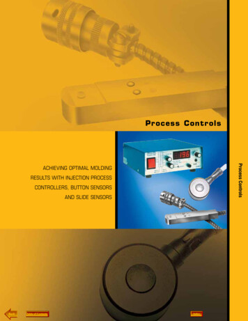
Process Controls64Button Mold Pressure SensorsPermanently InstalledMinimizes damage due to mishandling of sensors.Temperature CompensatedSpecial amplifiers that compensate for temperature changesare avoided.Constant OutputBecause each sensor is electrically identical, each sensorhas the same output. This similarity practically eliminatesthe need to recalibrate the readout system when sensors areexchanged. Only a slight readjustment of the zero setting ofthe readout system may be required when exchanging sensors.D-M-E Button Mold Pressure Sensors are used formeasuring pressures in conjunction with auxiliary recording and Therefore errors in calibration are non-existent and operatorscontrol equipment in injection, die cast and transfer molds. They will spend less time setting up control systems and recorders.provide a full-scale output of 2 millivolts per volt of excitation.Small SizeSuitable for small molds or molds where water lines,Three Modelssupport pillars, etc., inhibit the use of slide sensors.Available in 125, 500 and 2000 pounds force.InstallationHermetically SealedThe Button Sensor is usually installed under an ejectorAllows sensor to be used where moisture is present.pin and the shielded lead wire is run to the outside ofthe mold for mounting. To accommodate the buttonNIST TRACEABLEsensor, a slot and counterbored hole is machined into theSUPPLIED WITH CERTIFICATE OF CALIBRATIONejector plate. See installation information for details.500DIA.4951.35MAX.105 DIA.FemaleD-M-ECOMPANY.938SQ Button Mold Pressure SensorsBoth Models Available in 12, 24 and 36 inch lengthsProcess Controls.585 DIA. MAXA.719SQBUTTON SENSOR BS-412 & BS-413-C.375.372.120DIA. HOLE(#4).128 .004Male10 FEETBUTTON SENSOR CABLE BSC-10CABLE IS REQUIRED TOINTERFACE WITH IPC-01-01BUTTON SENSOREXTENSION CABLE*BUTTON MOLD PRESSURE SENSORSSupplied with soldered on flush mount connector Amphenol PT02A10-6S(Mating connector Amphenol PT06A10-6P(SR) not supplied).FORCEPOUNDS125MEASURES PRESSUREON PINS FROM:ITEM NUMBERA LENGTHBSC-106” LEADS12” LEADS18” LEADS 24” LEADS 32 Thru 3 32 (1 Thru 3mm) dia.BS411C6BS411C12BS411C18BS411C24– 16 Thru 3 16 (2 Thru 6mm) dia.–BS412C12–BS412C24BS412C36 16 Thru 2 (6 Thru 16mm) dia.–BS413C12–BS413C24BS413C3615001200031U.S. 800-626-6653N36” LEADSCanada 800-387-6600NLENGTH10 FEET*Mates with connector onbutton sensors above. AmphenolPT06A10-6P(SR) on each end.Use where required for monitoringand control equipmentwww.dme.net
Process Controls65Button Mold Pressure SensorsINSTALLATION INFORMATIONFLUSH MOUNTED CONNECTOREREF.½½.812R.3591/4 CENTRAL3/8 CENTRALLOCATE EJECTOR PIN FOR BUTTONSENSOR UNDER MOLDED PATH OR RUNNERFOR MULTIPLEMOUNTING1½ MIN.8C‘BORE 1/16 GREATER THAN EJECTORPIN HEAD DIA. FOR CLEARANCEINSTALL BUTTON SENSORAND CONNECTOR IN MOLD ASSHOWN FOR FLUSH MOUNTING.SLOT CAN BE WIDENEDTO ACCOMODATE EXCESSLEAD WIRE. HOLD DOWN WITHCOVER PLATE TO SUIT.1“ MIN.510 DIA.1/2SECTION A-A010000EJECTOR RETAINER PLATE.050 MINIMUMDEPTH C’BOREDRILL AND TAP FOR#4 SCREW 4 PLACES .25 DEEPLOCATE CENTRAL.578 005000WITH .578 DIM.EJECTOR PIN ORDUMMY PIN.010 MIN.CLEARANCE.719.359EJECTORPLATE.719E1“ MIN. TYP. TO EDGEOF CUT-OUT1“ MIN. FORCLEARANCE WHENINSTALLING CONNECTOR¼ MIN. SLOT FOR LEAD WIRE.BREAK ALL SHARP CORNERS.3751¼EJECTOR PLATE1“ MINLOCATE SENSOR SLOTSTO AVOID INTERFERENCEWITH OTHER PINS ORMOLD COMPONENTS.SECTION E-EEJECTOR RETAINERPLATEBUTTON SEAT MUST BE PARALLELWITH TOP OF EJECTOR PLATE WITHIN .003NOTE: When dummy pin installationis made. Altering mountingdimensions and location as requiredOUTSIDE BOX MOUNTEDINSTALL BUTTON UNDERPIN AS SHOWNDRILL AND TAPMOLD FOR #10SCREW - 4 PLACESDRILL 7/8 DIAMETERHOLE IN BOX AND MOUNTGROMMET. LOCATEHOLE TO SUIT.MOUNT BOX TO MOLDAS SHOWNProcess ControlsNOTE: When ejector plate is thicker than 1” connectormay be centered on plate thickness. Altering mountingdimensions as required slot for lead wire should bedepended as it approaches connector end as required.005.000 NOTE: When installing button sensorin mold pass button through holein cover and Hole in box beforeincorporating into mold under pinexcess wire may be left in box.BUTTON SENSORINSTALLED UNDER PIN.EJECTOR PINMOUNTED IN MOLDUNDER MOLDEDPART OR RUNNERDRILL 5/8 DIAMETERCLEARANCE HOLE INCOVER FOR MOUNTINGCONNECTORSPECIFICATIONSWIRING (black)(white)(green)(shield)WARNING:DO NOT REMOVE CONNECTOR FROM SENSORCABLE. CALIBRATIONWILL BE ALTERED.NOTE: MATING CONNECTOR IS AMPHENOL PT06A10-6P(SR).U.S. 800-626-6653NPRESSURE MEASUREMENT RANGE. 0 to 20,000 psi(FOR RECOMMENDED PIN DIAMETERS)FORCE RANGEIb.kg.ITEM NO. BS-411C .12560ITEM NO. BS-412C .500225ITEM NO. BS-413C .2000900MAXIMUM LOAD. 150% FULL SCALETEMPERATURE RANGE. 0 F T0 450 FTEMPERATURE COMPENSATION . 2% FULL SCALEINPUT .12V MAX.OUTPUT .2.0 mV/V FULL SCALEACCURACY. ¾% FULL SCALEREPEATABILITY. 0.1% FULL RANGE OUTPUTFULL RANGE DEFLECTION . LESS THAN .0008”CIRCUIT .4-ARM 350 OHM BRIDGECONNECTOR .AMPHENOL PT02A10-6SMATES WITH AMPHENOL PT06A10-6P (SR)Canada 800-387-6600Nwww.dme.netButton Mold Pressure SensorsDRILL AND TAPMOLD FOR #4SCREW - 4 PLACES
Process Controls66Slide Mold Pressure SensorsD-M-E Slide Mold Pressure Sensors are used formeasuring pressures in conjunction with auxiliary recordingand control equipment in injection and transfer molds. Theyprovide a constant, full-scale output of 2 millivolts per volt.Because each sensor is electrically identical, the need forrecalibration of control systems or recorders when a sensoris replaced is virtually eliminated. This means that errors incalibration are non-existent and operating personnel will nowhave an easier time setting up and operating control systemsand recorders.Constant OutputAll sensors have the same output. This eliminates the need torecalibrate the readout system when sensors are exchanged.Process ControlsTwo ModelsCovers ejector pin sizes from 1/16” to 1/2” diameter,eliminating the need for stocking several different load ranges.InstallationThe sensing element is housed in a rectangular slide thatplugs into a 3/8” deep by 1/2” wide slot, machined from theedge of the ejector plate to an ejector pin (slot machined insupport plate when using a dummy pin). When fully inserted,the sensing element of the slide is under the head of the pin.See installation information for details.Temperature CompensatedSpecial amplifiers are eliminated to compensate fortemperature changes.NIST TRACEABLESUPPLIED WITH CERTIFICATE OF CALIBRATION.492 REF.SPRING LOADEDBALL DETENTS (2) Slide Mold Pressure SensorsHermetically SealedAllows the sensor to be used at low temperatures wheremoisture is a problem.Easily RemovedAllows user to take sensor from one mold and place in another.375.000.003½7½SIDE VIEWREF.358 REF.SLIDE EXTENSIONMALE CONN.375 .005.005.000.005D-M-ECOMPANY10 FT3”SLIDE SEMSOR SS-405-C & SS-406-C10½“FEMALE CONN.MALE CONN.D-M-ECOMPANY10 FTSLIDE SENSOR CABLE SSC-10U.S. 800-626-6653NCanada 800-387-6600Nwww.dme.net
Process Controls67Slide Mold Pressure SensorsSLIDE MOLD PRESSURE SENSORSINSTALLATION INFORMATIONMEASURES PRESSURESON PINS FROM:ITEM NUMBERC‘BORE 1/16 GREATER THAN EJECTORPIN HEAD DIA. CLEARANCE510SS-405C1 16 THRU 3 16 (2 THRU 6mm) Dia.SS-406C3 16 THRU 1 2 (6 THRU 16mm) Dia.005.000SIDE EXTENSION250 RSECTION A-AITEM NUMBERLENGTHSSE-41871 2“SENSOR BLANKEJECTORRETAINER PLATEEJECTOR PIN ORDUMMY PIN.377.002 000ITEM NUMBERLENGTHSSB-41912“.010 CLEARANCEAA.375EJECTOR PLATE1/16 X 45 CHAM ON HEADOF PIN (1/32 CHAM WHENHEAD DIA. UNDER 3/8)SLIDE SENSOR EXTENSION CABLE**ITEM NUMBERLENGTHSSC-1010 ft.**Mates with connector on slide sensors above. Has Amphenolconnector No. PT01A10-6S(SR) on one end and Amphenol connectorNo. PT06A10-6P(SR) on the other end. Use where required formonitoring and control equipment. TAP No 10 24 HOLE TOPULL OUT BLANKWIRING ack)(white)(green)(shield)WARNING:DO NOT REMOVE CONNECTOR FROM SENSORCABLE. CALIBRATIONWILL BE ALTERED.U.S. 800-626-6653NSPECIFICATIONSPRESSURE MEASUREMENT RANGE. 0 to 20,000 psi(FOR RECOMMENDED PIN DIAMETERS)FORCE RANGE.Ib.kg.ITEM NO. SS-405C .500225ITEM NO. SS-406C .2000900MAXIMUM LOAD. 150% FULL SCALETEMPERATURE RANGE. 0 F T0 450 FTEMPERATURE COMPENSATION . 2% FULL SCALE/100 FINPUT .12V MAX.OUTPUT .2.0 mV/V FULL SCALEACCURACY. ¾% FULL SCALEREPEATABILITY. 0.1% FULL RANGE OUTPUTFULL RANGE DEFLECTION . LESS THAN .0008”CIRCUIT .4-ARM 350 OHM BRIDGECABLE LENGTH . 10 FEETCONNECTOR . AMPHENOL PT06A10-6P(SR)MATES WITH AMPHENOL PT01A10-6S(SR)Canada 800-387-6600Nwww.dme.netSlide Mold Pressure SensorsINSTALL SLIDE MOLD PRESSURE SENSORBLANK ITEM NO SSB 419 10 SUPPORT PINAND PLUG SLOT WHEN SENSOR IS NOTIN USE CUT TO SIZE AND FASTEN TO SUIT350Process Controls.050 MIN.DEPTH C’BORE
Process Controls68Using Process Controls and Monitoringto Achieve Optimal Molding ResultsD-M-E button sensors, slide sensors and injection process controllerscan be used for a number of applications. Assuming one is using newerinjection molding machine technology with 3-stage control, managing thepeak cavity pressure during pack (2nd stage) will guarantee consistentpart quality. Peak cavity pressure determines how much plastic is injectedinto the part. Having consistent peak pressure during injection, shot aftershot, guarantees that all parts in production are of the same size. This isreferred to as process control.Using Process Controls and Monitoring to Achieve Optimal Molding ResultsEnsuring part quality —everytime.Another application is that of process monitoring. By placing an ejectorpin and a sensor at the last location in the part to fill, the sensor can beused to determine whether a short shot occurred. By determining theminimum pressure that defines a filled part, monitoring the process candetermine whether a short shot has occurred. Many molders have usedthis method to scrap a suspected bad part because they would rather riskscrapping a good part than supplying a defective part to their customer.This is a fairly common practice for molders supplying certain industries,including automotive.Many customers use D-M-E sensors in conjunction with plant-widemonitoring systems to automatically control conveyors. If a specific rangeof cavity pressure is not realized during ejection, the part is automaticallyscrapped. Again, this practice of scrapping a potentially good part ratherthan supplying a bad part to a customer ensures that part quality remainsconsistently good.Process Controls The D-M-E Injection Process Controller (IPC) can operate in a coupledifferent ways. It can act as an amplifier to supply zero to one, zero tofive, or zero to 10 volts DC. It can also output a four to 20 milliamp signal.If the molding machine has cavity pressure control but no strain gaugeamplifier, the IPC can be used to fill the void. The IPC can also accepta relay contact closure indicating that injection forward is occurring. Itcan then use a pressure setpoint to trigger a relay contact to inform themolding machine that a specific cavity pressure has occurred. This actioninstructs the molding machine to go into a hold (3rd stage) state. Sincethere is a slight delay in triggering the machine, a slightly lower setpointis used than the peak pressure.The injection signal into the IPC also triggers a peak hold circuit so thatpeak cavity pressure is maintained on the display of the IPC until the endof injection.For more information about setting up process control and monitoringapplications, visit www.dme.net.U.S. 800-626-6653NCanada 800-387-6600Nwww.dme.netNext
Portable Cavity and Hydraulic Pressure Monitor and Controller . using a mold pressure sensor and a single setpoint to control filling and packing of the mold. By closely monitoring and . The 120 VAC unit comes with a standard wall outlet plug. U.S. 800-626-6653 N Canada 800-387-6600 N www.dme.net 63