Transcription
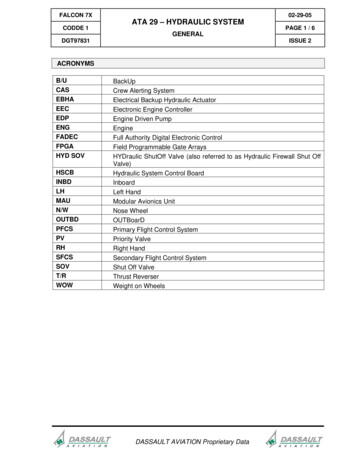
FALCON 7XCODDE 102-29-05ATA 29 – HYDRAULIC SYSTEMPAGE 1 / 6GENERALDGT97831ISSUE 2ACRONYMSB/UCASEBHAEECEDPENGFADECFPGAHYD pCrew Alerting SystemElectrical Backup Hydraulic ActuatorElectronic Engine ControllerEngine Driven PumpEngineFull Authority Digital Electronic ControlField Programmable Gate ArraysHYDraulic ShutOff Valve (also referred to as Hydraulic Firewall Shut OffValve)Hydraulic System Control BoardInboardLeft HandModular Avionics UnitNose WheelOUTBoarDPrimary Flight Control SystemPriority ValveRight HandSecondary Flight Control SystemShut Off ValveThrust ReverserWeight on WheelsDASSAULT AVIATION Proprietary Data
02-29-05PAGE 2 / 6FALCON 7XATA 29 – HYDRAULIC SYSTEMCODDE 1GENERALISSUE 2DGT97831INTRODUCTIONGENERALThe hydraulic power system provides pressure for actuation of:- Primary Flight Controls System (PFCS: ailerons, elevators, rudder and spoilers),- Secondary Flight Controls System (SFCS: slats, flaps and airbrakes),- landing gear, brakes and nose wheel steering,- Thrust reverser of engine 2.DASSAULT AVIATION Proprietary Data
FALCON 7XCODDE 102-29-05ATA 29 – HYDRAULIC SYSTEMPAGE 3 / 6GENERALDGT97831ISSUE 2FIGURE 02-29-05-00 - HYDRAULIC POWERDASSAULT AVIATION Proprietary Data
02-29-05PAGE 4 / 6FALCON 7XATA 29 – HYDRAULIC SYSTEMCODDE 1GENERALISSUE 2DGT97831HYDRAULIC POWERHydraulic power is supplied by:- The primary hydraulic systems during normal flight operation- The auxiliary hydraulic supplyo On ground if primary hydraulic power is not available or for maintenance operations,o In flight in case of failure of the primary hydraulic system.The primary hydraulic power supply features three independent hydraulic systems (referredto as A, B, and C systems), each operating with hydraulic fluid at a nominal pressure of3000 psi (207 bar).It is powered by five Engine Driven Pumps (EDP).The auxiliary hydraulic supply, which is provided by the electrical backup pump and selectorvalve, provide back-up power between 2900 psi (200 bar) and 1500 psi for system B as wellas power to systems A or B for ground maintenance activities.DASSAULT AVIATION Proprietary Data
FALCON 7XCODDE 102-29-05ATA 29 – HYDRAULIC SYSTEMPAGE 5 / 6GENERALDGT97831ISSUE 2FLIGHT DECK OVERVIEWCONTROLSCrew control of the Hydraulic system is performed- Primarily via the HYDRAULIC section of the overhead panel (OP)- Via the Fire Control Panel in case of engine fire.INDICATIONSCrew indications with regard to Hydraulic system are located in:- The HYDraulic synoptic- The STATus page synoptic for a recapitulative of main parameters concerning theHydraulic system,- The STATus synoptic / FAULT tab for fault messages- The ENG-CAS window for CAS messages.DASSAULT AVIATION Proprietary Data
02-29-05PAGE 6 / 6FALCON 7XATA 29 – HYDRAULIC SYSTEMCODDE 1GENERALISSUE 2DGT97831FIGURE 02-29-05-01 - FLIGHT DECK OVERVIEWDASSAULT AVIATION Proprietary Data
FALCON 7XCODDE 102-29-10ATA 29 – HYDRAULIC SYSTEMPAGE 1 / 8DESCRIPTIONDGT97831ISSUE 2GENERALEach of the three hydraulic systems contains:-A reservoir for storage of hydraulic fluid,-One to three hydraulic pumps,-An Hydraulic Shut Off Valve associated to each Engine Driven Pump,-A Priority Valve for systems A and B.FIGURE 02-29-10-00 - HYDRAULIC SYSTEMS SCHEMATICDASSAULT AVIATION Proprietary Data
02-29-10PAGE 2 / 8FALCON 7XATA 29 – HYDRAULIC SYSTEMCODDE 1DESCRIPTIONISSUE 2DGT97831GENERATIONGENERALThe pumps of the hydraulic system are driven:- Mechanically via the accessory gear box for the 5 Engine Driven Pumps (EDP),- Electrically for the backup pump.Repartition of hydraulic pumps on each hydraulic system is the following:- System A is powered by two EDP:o One on engine 1 (A1)o One on engine 3 (A3),- System B is powered by two EDP:o One on engine 2 (B2),o One on engine 3 (B3)o The electrical backup pump,- System C is powered by a single EDP:o On engine 2 (C2).Additionally to the normal hydraulic systems generation:- The spoilers feature a local Electrical Backup Hydraulic Actuator (EBHA),- The braking system and the thrust reverser feature an accumulator.RESERVOIRSEach of the three hydraulic systems stores hydraulic fluid in a dedicated reservoirembedding its own accumulator.Each reservoir is pressurized by its corresponding hydraulic system to avoid pump cavitationand draining. No bleed air is used to pressurize the hydraulic tanks.Fluid quantity can be visually checked on the reservoir itself or on the hydraulic synoptic.Fluid temperature for each reservoir is also given on the hydraulic synoptic.ENGINE DRIVEN PUMPS (EDP)GeneralThe Falcon 7X hydraulic system uses five EDP of two different sizes:- Systems A and B use a 1-gallon frame size pump,- System C uses a 0.5 gallon frame size pump.The self-regulating, piston-type EDP are driven by the accessory gearbox of thecorresponding engine.The regulated pressure output is 3000 50 psi.DASSAULT AVIATION Proprietary Data
FALCON 7XCODDE 102-29-10ATA 29 – HYDRAULIC SYSTEMPAGE 3 / 8DESCRIPTIONDGT97831ISSUE 2Depressurization modeThe EDP of system A and B feature an electrical depressurization valve to minimizeengine torque loads during engine ground start and restart:- EDP is depressurized when N2 is below 40% (engine speed increasing) and below15% (engine speed decreasing), hydraulic pressure being reduced approximately1000 psi.The depressurization mode is automatically commanded by the EEC of the engine.The depressurization mode is also automatically engaged in case of excessivetemperature of system A or B. In that case, the depressurization mode is controlled by adedicated control board named HSCB (Hydraulic System Control Board).The C2 pump has no depressurization capability.ELECTRICAL BACKUP PUMPGeneralThe electrical Backup Pump provides:- Back-up hydraulic power supply for system B,o mainly in case of a triple engine failure,o it is designed to allow an emergency descent with all engines out from 51,000ft- Power for ground maintenance activities on systems A and B:o For maintenance on system A, it is manually switched by using theFLIGHT/GROUND selectorNOTEPrior to flight, Backup pump selector valve should be set on Hydraulic B.When activated, the backup pump operates continuously and delivers approximately2,900 psi.The backup pump is supplied by the RH ESSential bus.The backup pump is air cooled by an internal fan attached to the motor rotor and isdesigned to provide sufficient cooling at or below 15,000 ft for a continuous use (no timelimitation).NOTEUse of Backup pump above 15,000 ft should be limited in order to avoid overheating.DASSAULT AVIATION Proprietary Data
02-29-10PAGE 4 / 8FALCON 7XATA 29 – HYDRAULIC SYSTEMCODDE 1DESCRIPTIONISSUE 2DGT97831OperationThe Backup Pump is activated:- Automatically: by the HSCB (Hydraulic System Control Board) when the four EDP ofsystems A and B are (failed) not producing power (A1, A3, B2 and B3), ie. in case ofa triple engine failure,- Manually: by setting the overhead panel BACKUP PUMP pushbutton to ON position.The backup pump can bet set to OFF, using the same BACKUP PUMP pushbutton of theoverhead panel.HYDRAULIC SYSTEM CONTROL BOARDThe Hydraulic System Control Board (HSCB):- Controls the backup pump,- Controls EDP A3, B3 and B2 depressurization valves in case of temperature increaseand B2 and B3 depressurization valves in case of backup pump producing pressure inON mode.BACKUP PUMP SELECT VALVEThe backup pump select valve is manually operated on ground:- Allows the backup pump to be switched to power system A for maintenance activitiesonly.- Incorporates a pin allowing latch in both the GROUND (system A powered) and FLIGHT(system B powered) positions- Switches both the suction and discharge lines of the backup pump from system B to A,no fluid mixing occurring between the two systems.An electrical position switch is used to annunciate a non standard flight configuration to thecockpit crew, which is any lever position other than “FLIGHT” position.DASSAULT AVIATION Proprietary Data
FALCON 7XCODDE 102-29-10ATA 29 – HYDRAULIC SYSTEMPAGE 5 / 8DESCRIPTIONDGT97831ISSUE 2FIGURE 02-29-10-01 - BACKUP PUMP SELECT VALVEEBHA, THRUST REVERSER AND PARK BRAKE ACCUMULATORSThe spoilers feature a dedicated Electrical Backup Hydraulic Actuator (EBHA), whichprovides local pressure with an internal accumulator in case of failure of the EDP C2.Two dedicated accumulators provide an hydraulic supply for:- Thrust reverser in case of a (total) system B hydraulic failure,- Park or emergency brake.¾ Refer to ATA 70 and 32 for additional information.DASSAULT AVIATION Proprietary Data
02-29-10PAGE 6 / 8FALCON 7XATA 29 – HYDRAULIC SYSTEMCODDE 1DESCRIPTIONISSUE 2DGT97831DISTRIBUTIONEach of systems A and B uses two Engine Driven Pumps (A1, A3, B2 and B3 pumps), as theprimary source of supply of pressurized hydraulic fluid for:-The primary and the secondary flight controls,-The landing gear operation, and nose wheel steering-Normal and park braking,-Thrust reverser.Priority valves on system A and B give priority to flight controls and brakes in case of flowdeficit.System C uses C2 pump to provide pressurized Hydraulic fluid to:-The spoilers-One barrel of right elevator-One barrel of right aileron.PRIORITY VALVESA priority valve is installed on system A and B ahead of the utility users of the hydraulicsystem giving flow delivery priority to the flight control components that are essential forflight and for the brakes system on ground.For example, the priority valves might be actuated when one EDP for system A or B is failedand the remaining pump produces insufficient flow to power the extension of landing gear,flaps, etc and to also power the flight controls: the priority valve then preserves pressure forthe flight controls.HYDRAULIC SHUT-OFF VALVEIn the event of an engine fire or hydraulic overheat, each EDP can be isolated from theHydraulic System through an electrically-controlled HYDraulic Shut-Off Valve (HYD SOV),located in the suction lines.When activated, the HYD SOV isolates the suction line from the pump, preventing hydraulicfluid from reaching the engine, should an engine fire occur.A thermal relief valve protects the downstream system when the HYD SOV is closed.The five HYD SOV can be manually activated by the crew members through five CLOSEswitches on the overhead panel and/or engine fire/handle button.DASSAULT AVIATION Proprietary Data
FALCON 7XCODDE 102-29-10ATA 29 – HYDRAULIC SYSTEMPAGE 7 / 8DESCRIPTIONDGT97831ISSUE 2FILTERINGFiltration components installed on the three hydraulic systems supply clean fluid to thehydraulic components.The filters contain:- An electrical differential pressure indicator for on condition maintenance supportpurpose,- A bypass valve to allow system operation with a clogged filter (return filter only).DASSAULT AVIATION Proprietary Data
FALCON 7X02-29-15ATA 29 – HYDRAULIC SYSTEMCODDE 1PAGE 1 / 12DESCRIPTION - SUPPLEMENTARY INFORMATIONDGT97831ISSUE 2DESIGN PRINCIPLESHydraulic system was designed considering following design principles:-Tube routing and placement of hydraulic components is designed so that no single aircraftfailure would cause loss of more than one hydraulic system and no two hydraulic systemfailures would result in complete loss of flight control,-Rotor burst considerations are addressed so at least one system is functional after a worstcase tri-sector burst,-No hydraulic generation system component is installed in the passenger or flight crewcompartments.DASSAULT AVIATION Proprietary Data
02-29-15FALCON 7XATA 29 – HYDRAULIC SYSTEMPAGE 2 / 12CODDE 1DESCRIPTION - SUPPLEMENTARY INFORMATIONISSUE 2DGT97831EQUIPMENT LOCATIONENGINE DRIVEN PUMPSEngine Driven Pump A1 is mounted on the engine 1.Engine Driven Pumps A2 and C2 are mounted on engine 2.Engine Driven Pumps A3 and B3 are mounted on engine 3.FIGURE 02-29-15-00 - ENGINE DRIVEN PUMPS LOCATIONFIGURE 02-29-15-01 - ENGINE DRIVEN PUMPS VIEWDASSAULT AVIATION Proprietary Data
FALCON 7XCODDE 102-29-15ATA 29 – HYDRAULIC SYSTEMPAGE 3 / 12DESCRIPTION - SUPPLEMENTARY INFORMATIONDGT97831ISSUE 2HYDRAULIC SYSTEM EQUIPMENTBackup pump, backup pump select valve and reservoirs are located in the servicecompartment.FIGURE 02-29-15-02 - HYDRAULIC SYSTEM EQUIPMENT LOCATIONDASSAULT AVIATION Proprietary Data
02-29-15PAGE 4 / 12FALCON 7XATA 29 – HYDRAULIC SYSTEMCODDE 1DESCRIPTION - SUPPLEMENTARY INFORMATIONISSUE 2DGT97831FIGURE 02-29-15-03 - HYDRAULIC EQUIPMENTSDASSAULT AVIATION Proprietary Data
FALCON 7X02-29-15ATA 29 – HYDRAULIC SYSTEMCODDE 1PAGE 5 / 12DESCRIPTION - SUPPLEMENTARY INFORMATIONDGT97831ISSUE 2ELECTRICAL POWER SUPPLYFollowing paragraph describes the power supply of the different equipment of the hydraulicsystem.Electrical protection is provided either:-By Solid State Power Controllers (SSPC) ,-By Circuit Breakers (CB).¾ Refer to ATA 24 – ELECTRICAL POWER for additional information.EQUIPMENTPOWER SUPPLYTYPE OF PROTECTIONBackup pumpRH EssentialCBEDP A1 SOVBattery 1CBEDP A3 SOVBattery 2CBEDP B2 SOVBattery 2CBEDP B3 SOVBattery 1CBEDP C2 SOVBattery 1CBEDP A1 depress valveRH EssentialSSPCEDP A3 depress valveLH EssentialSSPCEDP B2 depress valveLH EssentialSSPCEDP B3 depress valveRH EssentialSSPCLH HSCBLH EssentielCBRH HSCBRH EssentielCBDASSAULT AVIATION Proprietary Data
02-29-15PAGE 6 / 12FALCON 7XATA 29 – HYDRAULIC SYSTEMCODDE 1DESCRIPTION - SUPPLEMENTARY INFORMATIONISSUE 2DGT97831DETAILED ARCHITECTURE OF HYDRAULIC SYSTEMFIGURE 02-29-15-04 - HYDRAULIC SYSTEMS SCHEMATICDASSAULT AVIATION Proprietary Data
FALCON 7X02-29-15ATA 29 – HYDRAULIC SYSTEMCODDE 1PAGE 7 / 12DESCRIPTION - SUPPLEMENTARY INFORMATIONDGT97831ISSUE 2COMPONENTS DETAILED DESCRIPTIONRESERVOIRSEach of the three hydraulic systems contains a reservoir.FIGURE 02-29-15-05 - RESERVOIR ASSEMBLYSYSTEM ARESERVOIRSYSTEM BRESERVOIRSYSTEM CRESERVOIR450 cu. in575 cu. in200 cu. in(7.4 liters)(9.4 liters)(3.3 liters)The assembly is a bootstrap type, utilizing system high-pressure fluid acting on a piston andprovides the following functions:- Supply fluid to the system, or accept fluid from the system- Provide sufficient static pressure to deliver fluid to the pump- Collect air for manual removal with a bleed/relief valve.- Maintain sufficient pressure in the hydraulic system to energize seals for a period of 72hours after aircraft shutdown to minimize air ingress into the system.The reservoir provides the necessary fluid volume demanded by the hydraulic system.Changes in fluid volume due to thermal expansion/contraction, system leakage, anddifferential area of the user actuators have been taken into account in sizing the volume ofeach reservoir.DASSAULT AVIATION Proprietary Data
02-29-15PAGE 8 / 12FALCON 7XATA 29 – HYDRAULIC SYSTEMCODDE 1DESCRIPTION - SUPPLEMENTARY INFORMATIONISSUE 2DGT97831The major components of the reservoir assembly include:- Low-pressure storage chamber,- Bootstrap cylinder,- Maintenance free accumulator,- Pressure maintaining & dump valve,- Bleed / relief valve,- Quantity indicator,- Temperature transducer,- Temperature switch.FIGURE 02-29-15-06 - HYDRAULIC RESERVOIRLow-Pressure Storage ChamberThe low-pressure piston is acted upon by the bootstrap piston to maintain chamberpressure.System A and B reservoirs each utilize the same diameter storage chamber, while thesystem C reservoir utilizes a smaller storage chamber piston diameter.A drain provided on the atmospheric side of the piston head routes any leakage fluidoverboard.DASSAULT AVIATION Proprietary Data
FALCON 7X02-29-15ATA 29 – HYDRAULIC SYSTEMCODDE 1PAGE 9 / 12DESCRIPTION - SUPPLEMENTARY INFORMATIONDGT97831ISSUE 2Bootstrap CylinderThis assembly contains a small-area piston exposed to system pressure, nominally 3000psig (207 bar), which provides force to drive the low-pressure piston and pressurize thereservoir.Maintenance Free AccumulatorThis accumulator provides the pressure and volume to maintain seal energisation for aperiod of 72 hours after aircraft shutdown.Pressure Maintaining ValveIt is mounted in the reservoir manifold to provide for:- Maintaining bootstrap pressure without system pressure being applied,- To protect the reservoir from overpressurization.EDPSystem A and B EDPSystems A and B each use two Engine Driven Pumps (EDP), as the primary source ofsupply of pressurized hydraulic fluid for the flight control and utility systems.The Parker Model AP1V is a conventional axial piston type pump wherein a cylinderbarrel containing nine pistons is driven by an external power source.The pump timing and displacement controls provide for low-pressure ripple and smoothresponse to rapid changes in flow demand. Each of the System A & B EDP incorporatesan integral attenuator ball on the discharge to provide pressure ripple and noisereduction. Depressurization modeThe FADEC will energize the EDP de-pressurization solenoids to minimize enginedrag torque for ground starts and for in air engine restarts.If all three engines are non-operational during flight but are windmilling at a speedgreater than 15% N2, the EDP A1, A3, B3, and B2 will not be de-pressurized sothat they can provide limited hydraulic power to the hydraulic systems from thewindmilling engines: PFCS.The EDP will be depressurized when windmilling engine speed reduces below 15%N2 to minimize the engine load during a relight attempt. The pump will produce fullpressure when its respective engine speed is greater than 40% on increasingspeed to minimize starting and windmilling torque loads on that engine.The Hydraulic System Controller will energize the EDP de-pressurization solenoidsto minimize heat rejection into the system, if required.DASSAULT AVIATION Proprietary Data
02-29-15FALCON 7XATA 29 – HYDRAULIC SYSTEMPAGE 10 / 12CODDE 1DESCRIPTION - SUPPLEMENTARY INFORMATIONISSUE 2DGT97831EDP A3 or B2 will be de-pressurized when the system fluid reaches 92 C tominimize heat rejection into the system (if EDP A1 or B3 is producing pressure).If the Backup Pump is commanded on and is producing pressure, EDP B3 and B2will be depressurized (to protect the Standby Pump).System C EDPThis pump provides same functions as EDP of systems A and B.The operation and pressure control features of the System C EDP are very similar to theSystem A & B EDP. However, due to its smaller displacement and subsequently lowerload on the engine gearbox, a depressurization valve and solenoid are not included withthis pump.PRESSURE TRANSDUCERSThe pressure transducer transmits electrical signals, proportional to each hydraulic systempressure, to the crew members for monitoring of pressure in each system.There is one pressure transducer located downstream of the filter pressure element in eachsystem module (3 total).PRESSURE SWITCHESEach hydraulic pump output (the EDP and the Backup Pump) is monitored by a dedicatedpressure switch. These switches are used to annunciate hydraulic pump specific faults tothe cockpit crew when pump pressure falls below a predetermined value.BACKUP PUMP SELECT VALVEThis valve is used to power system A for maintenance activities only. The valve will switchboth the suction and discharge lines of the backup pump from system A to B.The select valve is designed to prevent any possibility of fluid propagating from one systemto another by utilizing rip-stop construction, such that any structural failure will not result inthe loss of both system A and B hydraulic pressure.The valve incorporates an integral pin to allow latching in both the “GROUND” (System Apowered) and “FLIGHT” (System B powered) positions. An electrical switch is provided tostatus spool position to prevent dispatch with the valve set to the “GROUND” position.DASSAULT AVIATION Proprietary Data
FALCON 7XCODDE 102-29-15ATA 29 – HYDRAULIC SYSTEMPAGE 11 / 12DESCRIPTION - SUPPLEMENTARY INFORMATIONDGT97831ISSUE 2FIGURE 02-29-15-07 - BACKUP PUMP SELECT VALVEHYDRAULIC SYSTEM CONTROL BOARDThe HSCB controls the backup pump and EDP A3, B3 and B2 depressurization solenoids.The HSCB will depressurize the EDP to control fluid temperature.The HSCB will command the EDP B3 and B2 pumps to depress when the standby pump iscommanded ON.The HSCB implements the logic using two electronic components called FieldProgrammable Gate Arrays (FPGA):- One FPGA is used to implement the logic for EDP A3 and B2 depress solenoids.- The other is used to implement the logic for the backup pump and EDP B3 depresssolenoid.Circuits for the two FPGA are powered by different buses. Therefore, the loss of one bus willonly disable part of the HSCB.DASSAULT AVIATION Proprietary Data
FALCON 7XCODDE 102-29-20ATA 29 – HYDRAULIC SYSTEMPAGE 1 / 8CONTROLS AND INDICATIONSDGT97831ISSUE 2CONTROLSThe hydraulic system is mainly controlled through the switches of the HYDRAULICS sectionof the Overhead Panel:-The five Hydraulic Shut-Off Valves (HYD SOV) are controlled by SHUT OFF A1, A3, B2,B3 and C2 guarded pushbuttons,-The backup pump is controlled by the "BACKUP PUMP" pushbutton.FIGURE 02-29-20-00 - HYDRAULICS OVERHEAD PANEL CONTROLThe five HYD SOV can also be activated through the respective engine FIRE guardedpushbuttons on the Fire Control Panel.FIGURE 02-29-20-01 – HYDRAULIC FIREWALL SHUT-OFF VALVE CONTROLON FIRE CONTROL PANELDASSAULT AVIATION Proprietary Data
02-29-20FALCON 7XATA 29 – HYDRAULIC SYSTEMPAGE 2 / 8CODDE 1CONTROLS AND INDICATIONSISSUE 2DGT97831SYNTHETIC TABLECONTROLFUNCTIONTO ACTIVATEOPENUnlighted open(normal): HYDSOV is open,-CLOSE: HYDSOV is closed.EDP A1HYD SOVopenEDP A1HYD SOVclosedGuardedpushbuttons controlthe closing of thecorrespondingHYD SOV:-SYNOPTICTO DEACTIVATECLOSEEDP A1HYD SOVis not in itscommandedpositionEDP A1HYD SOVinvalid dataDASSAULT AVIATION Proprietary Data
FALCON 7X02-29-20ATA 29 – HYDRAULIC SYSTEMCODDE 1PAGE 3 / 8CONTROLS AND INDICATIONSDGT97831ISSUE 2CONTROLFUNCTIONTO ACTIVATESYNOPTICTO DEACTIVATEBackuppumpstopped andready tosupplySystem BNormalBackuppumpstarted andsupplyingSystem BBackup pumpswitch controls theBackup PumpThis pushbuttoncycles through:-Unlighted auto:Backup Pumpstarts when thepressure dropsin systems Aand B,-ON: BackupPump runscontinuously,-ONON moderunningOFFOFF modeOFF: BackupPump shutdownor failure.Short push:Normal/OFFInvalid dataLong push: ON.No control available forcrew members.Indicating a groundmaintenanceoperation.TestDASSAULT AVIATION Proprietary Data
02-29-20PAGE 4 / 8FALCON 7XATA 29 – HYDRAULIC SYSTEMCODDE 1CONTROLS AND INDICATIONSISSUE 2DGT97831INDICATIONSIndications related to the Hydraulic system are provided within the HYDraulic synoptic andwithin the STATus page.The HYDraulic (HYD) synoptic page displays the three hydraulic systems and the distributionof users between the systems:-The five EDP, the backup pump and the five Firewall Shutoff Valves status are indicatedby colour symbols and/or text fields-The button WHEELS allow to access tire pressure and brake temperature information(these data are described in ATA 32)-The following indications are available:oPressure of each hydraulic system,oFluid quantity of each hydraulic system,oFluid temperature of each hydraulic system,oShut-Off Valve positions (open, closed, transition),oAccumulators pressure (park brake, thrust reverser being not monitored).FIGURE 02-29-20-02 - HYDRAULIC SYNOPTIC IN NORMALDASSAULT AVIATION Proprietary Data
FALCON 7XCODDE 102-29-20ATA 29 – HYDRAULIC SYSTEMPAGE 5 / 8CONTROLS AND INDICATIONSDGT97831ISSUE 2Hydraulic level indicationsFIGURE 02-29-20-03 - HYDRAULIC LEVEL INDICATORSHydraulic fluid pressure indicationsFIGURE 02-29-20-04 - HYDRAULIC FLUID PRESSURESDASSAULT AVIATION Proprietary Data
02-29-20FALCON 7XATA 29 – HYDRAULIC SYSTEMPAGE 6 / 8CODDE 1CONTROLS AND INDICATIONSISSUE 2DGT97831Hydraulic pump statusRunningNot runningFailedInvalid dataFIGURE 02-29-20-05 - HYDRAULIC PUMP STATUSEquipment statusIn normal operation, symbols are green. If a failure occurs in a system, the symbols ofequipment powered by this system become amber.For flight control actuators connected to systems A and B, or A and C, or B and C, thecorresponding symbols are:- Green, in normal operating conditions,- Amber, in case of total hydraulic power loss,- Half green / half amber in case of loss of one system.FIGURE 02-29-20-06 - SYMBOLS OF FLIGHT CONTROLS CONNECTED TO A AND BDASSAULT AVIATION Proprietary Data
FALCON 7XCODDE 102-29-20ATA 29 – HYDRAULIC SYSTEMPAGE 7 / 8CONTROLS AND INDICATIONSDGT97831ISSUE 2Park brake accumulatorFIGURE 02-29-20-07 - PARK BRAKE ACCUMULATORDASSAULT AVIATION Proprietary Data
02-29-20FALCON 7XATA 29 – HYDRAULIC SYSTEMPAGE 8 / 8CODDE 1CONTROLS AND INDICATIONSISSUE 2DGT97831STATUS synopticAt the top of the STATus page, following information on the three Hydraulic systems aresummarized:- Hydraulic quantity,- Hydraulic pressure,- Hydraulic Temperature.FIGURE 02-29-20-08 - STATUS SYNOPTIC PAGEDASSAULT AVIATION Proprietary Data
FALCON 7XATA 29 – HYDRAULIC SYSTEM02-29-25CODDE 1CONTROL AND INDICATIONS - SUPPLEMENTARYINFORMATIONPAGE 1 / 2DGT97831ISSUE 2No supplementary information to be provided on Controls and Indications at present time.DASSAULT AVIATION Proprietary Data
FALCON 7XCODDE 102-29-30ATA 29 – HYDRAULIC SYSTEMPAGE 1 / 2SYSTEM PROTECTIONSDGT97831ISSUE 2SYSTEM MONITORINGMonitoring of following parameters is provided by the system:-Hydraulic fluid pressure downstream of EDP or back up pump,-Temperature of the Hydraulic fluid,-Hydraulic fluid quantity in each tank,-Position of the back up pump selector for flight,-Condition of the filters.¾ Refer to CODDE2 for a complete list and description of CAS messages.DASSAULT AVIATION Proprietary Data
02-29-30PAGE 2 / 2FALCON 7XATA 29 – HYDRAULIC SYSTEMCODDE 1SYSTEM PROTECTIONSISSUE 2DGT97831ACTIVE PROTECTIONSOVERPRESSURE PROTECTIONMain systemEach hydraulic system comprises a pressure relief valve located in the filter manifold,protecting the system in the event of a runaway pump compensator.ReservoirA bleed and relief valve is integrated to each system reservoir for air removal andoverpressure protection.OVERHEAT PROTECTIONFor Systems A, B:- EDP A3 and B2 are depressurized automatically when the hydraulic fluid gets too hot.- This depressurization is controlled by a fluid temperature switch located in the lowpressure section of each system reservoir.Additionally, in case of high temperature within the reservoirs of systems A and B:- Hydraulic fluid is routed to an overboard drain- This is controlled through a thermal fuse:o System A: when fluid reaches 143 Co System B: when fluid reaches 177 CFor System C:- Hydraulic Shut Off Valve C2 is automatically closed when the hydraulic fluid gets toohot: 125 C.- This is controlled by a fluid temperature switch located in a tee fitting directly mounted inthe system return port.PRIORITY VALVESAs mentioned in the "DESCRIPTION" sub-section, a priority valve is installed on system Aand B ahead of the utility users of the hydraulic system giving pressure delivery priority tothe flight control components that are essential for flight and for the brakes system onground.DASSAULT AVIATION Proprietary Data
FALCON 7XATA 29 – HYDRAULIC SYSTEM02-29-35CODDE 1SYSTEM PROTECTIONS - SUPPLEMENTARYINFORMATIONPAGE 1 / 2DGT97831No supplementary information to be provided on system protection at present time.DASSAULT AVIATION Proprietary DataISSUE 2
FALCON 7XCODDE 102-29-40ATA 29 – HYDRAULIC SYSTEMPAGE 1 / 2GROUND OPERATIONDGT97831ISSUE 2HYDRAULIC FILLING VALVE¾ Refer to Ground Servicing manual.DASSAULT AVIATION Proprietary Data
The primary hydraulic power supply features three independent hydraulic systems (referred to as A, B, and C systems), each operating with hydraulic fluid at a nominal pressure of 3000 psi (207 bar). It is powered by five Engine Driven Pumps (EDP). The auxiliary hydraulic supply, whi