Transcription
Basic Hydraulics andPneumaticsModule 1: Introduction to HydraulicsPREPARED BYIAT Curriculum UnitJanuary 2011 Institute of Applied Technology, 2011
ATM 1122 – Basic Hydraulics and PneumaticsModule 1: Introduction to HydraulicsModule ObjectivesAfter the completion of this module, the student will be able to: Identify the common uses of hydraulic systems. Determine that liquids are incompressible. Identify the fundamental parts of a hydraulic system. Observe how hydraulic components can be connected together toconstruct a hydraulic circuit. Identify the main components of the hydraulic work station TP 501. Explain the main parts of the hydraulic power pack. Explain the importance of using standard hyrdraulic symbols. Identify the basic hydraulic laws. Calculate the piston area, force, and pressure. Explain Pascal’s law and apply it on different examples. Differentiate between the flow rate and flow velocity. Demonstrate the continuity equation. Calculate the area, velocity, and flow rate at different sections of a pipe. Describe how to read a pressure gauge in the US and SI units. Set the pressure gauge of the hydraulic power pack to a certain pressure.
ATM 1112 – Basic Hydraulics and PneumaticsModule Contents1Introduction . 32Uses of hydraulics . 32.1 Common examples of hydraulic systems . 42.1.1 Vehicle brake hydraulic systems. 42.1.2 Vehicle power steering . 42.1.3 Hydraulic jack. 52.1.4 Aircraft hydraulic systems . 53Hydraulic system components. 63.13.23.34Hydraulic power pack . 7Activity 1: Hydraulic station component identification . 7Hydraulic symbols. 8Hydraulics Fundamental laws. 94.1 Pressure . 94.2 Pascal’s Law. 104.3 Liquid flow . 124.3.1 Flow rate versus flow velocity . 124.3.2 The continuity equation. 145Reading the pressure gauge. 165.16Activity 2: Setting the hydraulic pressure to 30 bar. 17Supplementary resources. 17References . 172Module 1: Introduction to Hydraulics
ATM 1122 – Basic Hydraulics and Pneumatics1IntroductionAll machines require some type of power source and a way of transmitting thispower to the point of operation. The three methods of transmitting power are: Mechanical Electrical FluidIn this course we are going to deal with the third type of power transmissionwhich is the Fluid PowerFluid power is the method of using pressurized fluid to transmit energy. Liquidor Gas is referred to as a fluid. Accordingly, there are two branches of fluidpower; Pneumatics, and Hydraulics.Hydraulic systems use liquid to transfer force from one point to another.Pneumatic systems use air to transfer force from one point to another. Air is Compressible: (This describes whether it is possible to force an object into a smallerspace than it normally occupies. For example, a sponge is compressible because it can besqueezed into a smaller size), and liquid is Incompressible: (The opposite to compressible. When a “squeezing” force is appliedto an object, it does not change to a smaller size. Liquid, for example hydraulic fluid,possesses this physical property).It is this difference that makes hydraulic and pneumatic systems behave indifferent ways. This module focuses on hydraulics.Hydraulic systems are commonly used where mechanisms require large forcesand precise control. Examples include vehicle power steering and brakes,hydraulic jacks and heavy earth moving machines.Liquid is ideal for transferring a force from the control mechanism to themechanism doing the work. For example transferring force from the brakepedal to the wheel brake in a car. Because liquid does not compress, ittransfers all the force and enables precise movement.2Uses of hydraulicsHydraulics plays an important role in many industries; there are a lot ofhydraulic applications in manufacturing, transportation, and constructionsectors. Hydraulics systems are used where large, precise forces are required.Module 1: Introduction to Hydraulics3
ATM 1112 – Basic Hydraulics and Pneumatics2.1Common examples of hydraulic systems include:2.1.1 Vehicle brake hydraulic systemsThefunctionofavehicleBrake pedalMastercylinderbraking system is to stop orslow down a moving vehicle.Whenthebrakepedalispressed as illustrated in Fig.Brakelines1.1, the hydraulic pressure istransmitted to the piston in thebrake caliper of the brakes.FrontbrakecalipersRear wheelcylinderpistonsThe pressure forces the brakepads against the brake rotor,whichisrotatingwithPadsRotorthewheel.The friction between the brakeFig.1.1: A schematic diagram of the vehicle’shydraulic brake system.pad and the rotor causes the Tip: Watch the hydraulic brake system video.wheel to slow down and thenstop.2.1.2 Vehicle power steeringThevehiclepowersteeringHydraulic pumpsystem uses hydraulic oil, thehydraulic pump supplies the oilthrough the control valves tothe power cylinder as shown inFig. 1.2. The major advantagePower cylinderControlvalveof using this system is to turnthe vehicle’s wheels with lesseffort.4Fig.1.2:Vehicle hydraulic power steeringsystemModule 1: Introduction to Hydraulics
ATM 1122 – Basic Hydraulics and Pneumatics2.1.3 Hydraulic jackIn a hydraulic jack, a small piston(pumping piston) transmits pressurethrough the oil to a large piston(powerpiston)throughacheckvalve, resulting in the weight beinglifted as shown in Fig.1.3.(a) Hydraulic jackTip: Watch the hydraulic jack video.Oil reservoirHandleWeightPumping pistonInlet checkvalve (allowsthe oil tomove in onlyone direction)PowerpistonOutlet check valve(allows the oil to movein only one direction)(b) Hydraulic jack schematic diagramFig.1.3: (a) hydraulic jack. (b) Schematic diagram of the hydraulic jack.2.1.4 Aircraft hydraulic systemsAllmodernaircraftcontainhydraulic systems to operatemechanisms, such as: Flaps (Fig. 1.4a) Landing gear (Fig. 1.4a)The hydraulic pump that iscoupled to the engine provideshydraulic power as illustratedLanding gearsFlaps(a) Landing gears and flapsModule 1: Introduction to Hydraulics5
ATM 1112 – Basic Hydraulics and Pneumaticsby Fig. 1.4b.TransmissionlinesPower is also distributed toHydraulicpumpsystems through the aircraftLandinggearby transmission lines.ActuatingCylinderHydraulic power is convertedtomechanicalpowerbymeans of an actuating cylinderEnginepoweror hydraulic motor.(b) Landing gear schematic diagramFig.1.4: (a) Flaps and landing gears.(b)Schematic diagram of the landing gearhydraulic system.3Hydraulic system componentsAll industrial hydraulic systems consist of the following basic components1. Power input device: The pump and motor together are called thepower input device; the pump provides power to the hydraulic system bypumping oil from the reservoir/tank. The pump’s shaft is rotated by anexternal force which is most often an electric motor as illustrated in Fig1.5. Tip: “Watch the hydraulic system video”Power input deviceControl deviceTankValveMotorPumpLiquidPipes or tubesPower output deviceActuatorFig.1.5: The basic components of a Hydraulic system6Module 1: Introduction to Hydraulics
ATM 1122 – Basic Hydraulics and Pneumatics2. Control device: Valves control the direction, pressure, and flow of thehydraulic fluid from the pump to the actuator/cylinder.3. Power output device: The hydraulic power is converted to mechanicalpower inside the power output device. The output device can be either acylinder which produces linear motion or a motor which produces rotarymotion.4. Liquid: the liquid is the medium used in hydraulic systems to transmitpower. The liquid is typically oil, and it is stored in a tank or reservoir.5. Conductors: The conductors are the pipes or hoses needed to transmitthe oil between the hydraulic components.3.1Hydraulic power packThe hydraulic power pack combines the pump, the motor, and the tank. Thehydraulic power pack unit provides the energy required for the hydraulic system.The parts of the hydraulic power pack unit are shown in Fig. 1.6.Fig.1.6: The main parts of the hydraulic power pack3.2Activity 1: Hydraulic station component identificationIn this activity, you will identify the components of the Festo Hydraulic workstation in your lab:1. Locate the power pack unit and identify its parts.2. Locate the out put device (actuators).3. Locate the control devices (valves).4. Locate the conductors (hoses).Module 1: Introduction to Hydraulics7
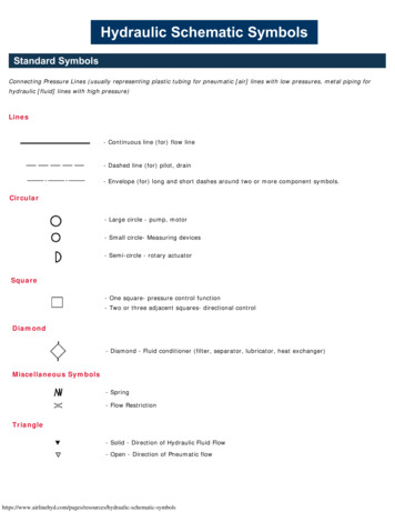
ATM 1112 – Basic Hydraulics and Pneumatics3.3Hydraulic symbolsThe way hydraulic components directand control liquid around a circuit canbe complex. This would cause difficulty(a) Electric motorfor one engineer explaining to anotherengineer how the circuit works. Acommonformofrepresentingcomponents and circuits is used to(b) Hydraulic pumpmore easily explain what is sesrepresent(c) Tank or reservoircomponents and the ways in whichthey are connected to form circuits. Fig.1.7 shows some of the components’symbols used in hydraulics.(d)Pressure relief valveThe symbols don’t show the component Fig.1.7: (a) Electric motor. (b)Hydraulic pump. (c) Tank or reservoir.construction, or size, however, it is a (d) Pressure relief valve.standard form that is used by allengineers to represent that specificcomponent.The simplified and detailed symbols of(a) Simplifiedthe hydraulic power pack are shown inFig. 1.8.(b) DetailedFig.1.8: (a) Simplified symbol of thehydraulic power pack. (b) Detailedsymbol of the hydraulic power pack.8Module 1: Introduction to Hydraulics
ATM 1122 – Basic Hydraulics and Pneumatics4Fundamental laws of HydraulicsAll hydraulic systems operate following a defined relationship between area,force and pressure. Laws have been established to explain the behavior ofhydraulic systems. Hydraulic systems use the ability of a fluid to distribute anapplied force to a desired location.4.1PressureWhen a force (F) is applied on anarea (A) of an enclosed liquid, apressure (P) is produced as shownin Fig. 1.9.Pressure is the distribution of agiven force over a certain area.Pressure can be quoted in bar,pounds per square inch (PSI) or Fig. 1.9: Illustration of pressure definitionPascal (Pa)Pressure ForceAreaWhere force is in newtons (N) and area is in square meters (m2).1 Pascal (Pa) 1 N/m2.1 bar 100,000 Pa 105 Pa.10 bar 1 MPa (mega Pascals)In hydraulic systems, the engineer often has the force in newtons and the areain square millimeters.1 N/mm2 1 MPa 10 barIf the pressure is calculated using a force in newtons, and area in squaremillimeters, the pressure in bar can be calculated.P F1000 N 0.33 N / mm 2 0.33 MPa 3.3 bar2A 3000 mmNote: To convert from N/mm2 to bar, multiply by 10, and to convert from barto N/mm2, divide by 10.Module 1: Introduction to Hydraulics9
ATM 1112 – Basic Hydraulics and PneumaticsExample 1-1.A cylinder is supplied with 100 bar pressure; its effective piston surface isequal to 700 mm2. Find the maximum force which can be attained.P 100 bar 100/10 10 N/mm2.A 700 mm2.F P.A 10X700 7000 N 7 kN4.2Pascal’s LawPascal’s law states that: “The pressure in a confined fluid is transmitted equally tothe whole surface of its container” Accordingly, the pressure at any point in abody of fluid is the same in any direction as shown in Fig. 1.10a.Fig.1.10b shows that, if adownward force is appliedto piston A, it will betransmittedthroughthesystem to piston B.According to Pascal’s law,the pressure at piston A(P1) equals the pressureat piston B (P2)(a) Pascal’s lawPiston APiston B(b)Power transmissionFig.1.10: (a) Pascal’s law. (b) Power transmissionin an enclosed system.P1 P210Module 1: Introduction to Hydraulics
ATM 1122 – Basic Hydraulics and PneumaticsFluid pressure is measured in terms of the force exerted per unit area.P FAP1 F1A1P2 F2A2F1 F2 A1 A2The values F1, A2 can be calculated using the following formula:F1 A1 F2A F2, and A2 1A2F1Example 1-2.In Fig.11, find the weight of the car in N, if the area of piston A is 600 mm2, thearea of piston B is 10500 mm2, and the force applied on piston A is 500 N.Solution:P1 P2F1 F2 A1 A2F2 F2 F1 A2A1500 10500600F2 8750 N 8.75 kNExample 1-3.In Fig 1.11, if the weight of the car is 10,000 N, the diameter of piston A is 10mm, and the force applied on piston A is 250 N. Calculate the radius of pistonB.Module 1: Introduction to Hydraulics11
ATM 1112 – Basic Hydraulics and PneumaticsSolution:1. Calculate the area of piston A, the piston shape is circular as shown in Fig.1.10a, accordingly the area will be calculated using the following formula.A1 π2(10) 2D 3.14 78.5 mm 2 ,44F1 250 N , F2 10,000 N2. Apply Pascal’s lawP1 P2F1 F2 A1 A23. Use Pascal’s law to calculate the area of piston BA2 A2 A1 F2F178.5 10,000 3140 mm 22502A2 π ( D2 ) 3140 mm 244. Find the diameter of piston B( D2 ) 2 A2 3140 4π314D2 4.34
(b) Hydraulic jack schematic diagram Fig.1.3: (a) hydraulic jack. (b) Schematic diagram of the hydraulic jack. 2.1.4 Aircraft hydraulic systems All modern aircraft contain hydraulic systems to operate mechanisms, such as: Flaps (Fig. 1.4a) Landing gear (Fig. 1.4a) The hydraulic pump that is coupled to the engine provides