Transcription
Architectural Modeling and Analysisfor Safety EngineeringDanielle Stewart1(B) , Michael W. Whalen1 , Darren Cofer2 ,and Mats P.E. Heimdahl11Department of Computer Science and Engineering,University of Minnesota, 200 Union Street, Minneapolis, MN 55455, USA{dkstewar,whalen,heimdahl}@cs.umn.edu2Advanced Technology Center, Rockwell Collins,400 Collins Rd. NE, Cedar Rapids, IA 52498, USAdarren.cofer@rockwellcollins.comAbstract. Architecture description languages such as AADL allowsystems engineers to specify the structure of system architectures andperform several analyses over them, including schedulability, resourceanalysis, and information flow. In addition, they permit system-levelrequirements to be specified and analyzed early in the developmentprocess of airborne and ground-based systems. These tools can also beused to perform safety analysis based on the system architecture andinitial functional decomposition.Using AADL-based system architecture modeling and analysis toolsas an exemplar, we extend existing analysis methods to support systemsafety objectives of ARP4754A and ARP4761. This includes extensionsto existing modeling languages to better describe failure conditions, interactions, and mitigations, and improvements to compositional reasoningapproaches focused on the specific needs of system safety analysis. Wedevelop example systems based on the Wheel Braking System in SAEAIR6110 to evaluate the effectiveness and practicality of our approach.Keywords: Model-based systems engineeringengineering1· Fault analysis · SafetyIntroductionSystem safety analysis techniques are well established and are a required activityin the development of commercial aircraft and safety-critical ground systems.However, these techniques are based on informal system descriptions that areseparate from the actual system design artifacts, and are highly dependent onthe skill and intuition of a safety analyst. The lack of precise models of thesystem architecture and its failure modes often forces safety analysts to devotesignificant effort to gathering architectural details about the system behaviorfrom multiple sources and embedding this information in safety artifacts, suchas fault trees.c Springer International Publishing AG 2017 M. Bozzano and Y. Papadopoulos (Eds.): IMBSA 2017, LNCS 10437, pp. 97–111, 2017.DOI: 10.1007/978-3-319-64119-5 7
98D. Stewart et al.While model-based development (MBD) methods are widely used in theaerospace industry, they are generally disconnected from the safety analysisprocess itself. Formal model-based systems engineering (MBSE) methods andtools now permit system-level requirements to be specified and analyzed earlyin the development process [3,7,8,21,22,26]. These tools can also be used toperform safety analysis based on the system architecture and initial functionaldecomposition. Design models from which aircraft systems are developed can beintegrated into the safety analysis process to help guarantee accurate and consistent results. This integration is especially important as the amount of safetycritical hardware and software in domains such as aerospace, automotive, andmedical devices has dramatically increased due to desire for greater autonomy,capability, and connectedness.Architecture description languages, such as SysML [10] and the Architecture Analysis and Design Language (AADL) [1] are appropriate for capturingsystem safety information. There are several tools that currently support reasoning about faults in architecture description languages, such as the AADLerror annex [18] and HiP-HOPS for EAST-ADL [6]. However, these approachesprimarily use qualitative reasoning, in which faults are enumerated and theirpropagations through system components must be explicitly described. Givenmany possible faults, these propagation relationships become complex and it isalso difficult to describe temporal properties of faults that evolve over time (e.g.,leaky valve or slow divergence of sensor values). This is likewise the case withtools like SAML that incorporate both qualitative and quantitative reasoning[11]. Due to the complexity of propagation relationships, interactions may alsobe overlooked by the analyst and thus may not be explicitly described withinthe fault model.In earlier work, University of Minnesota and Rockwell Collins developed anddemonstrated an approach to model-based safety analysis (MBSA) [14,16,17]using the Simulink notation [20]. In this approach, a behavioral model of (sometimes simplified) system dynamics was used to reason about the effect of faults.We believe that this approach allows a natural and implicit notion of fault propagation through the changes in pressure, mode, etc. that describe the system’sbehavior. Unlike qualitative approaches, this approach allows uniform reasoning about system functionality and failure behavior, and can describe complextemporal fault behaviors. On the other hand, Simulink is not an architecturedescription language, and several system engineering aspects, such as hardwaredevices and non-functional aspects cannot be easily captured in models.This paper describes our initial work towards a behavioral approach to MBSAusing AADL. Using assume-guarantee compositional reasoning techniques, wehope to support system safety objectives of ARP4754A and ARP4761. To makethese capabilities accessible to practicing safety engineers, it is necessary toextend modeling notations to better describe failure conditions, interactions, andmitigations, and provide improvements to compositional reasoning approachesfocused on the specific needs of system safety analysis. These extensions involvecreating models of fault effects and weaving them into the analysis process.
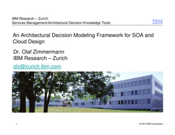
Architectural Modeling and Analysis for Safety Engineering99To a large extent, our work has been an adaptation of the work of Joshi et al.in [14,16,17] to the AADL modeling language.To evaluate the effectiveness and practicality of our approach, we developedan architectural model of the Wheel Braking System model in SAE AIR6110.Starting from a reference AADL model constructed by the SEI instrumentedwith qualitative safety analysis information [9], we added behavioral contractsto the model. In so doing, we determine that there are errors related to (manually constructed) propagations across components, and also an architecture thatcontains single points of failure. We use our analyses to find these errors.2Example: Wheel Brake SystemAs a preliminary case study, we utilized the Wheel Brake System (WBS)described in [2] (previously found in ARP4761 Appendix L). This ficticious aircraft system was developed to illustrate the design and safety analysis principlesof ARP4754A and ARP4761. The WBS is installed on the two main aircraftlanding gears and is used during taxi, landing, and rejected take off. Brakingis either commanded manually using brake pedals or automatically by a digitalcontrol system with no need for the pedals (autobrake). When the wheels havetraction, the autobrake function will provide a constant smooth deceleration.Each wheel has a brake assembly that can be operated by two independenthydraulic systems (designated green and blue). In normal braking mode, thegreen hydraulic system operates the brake assembly. If there is a failure in thegreen hydraulics, the system switches to alternate mode which uses the bluehydraulic system. The blue system is also supplied by an accumulator which isa device that stores hydraulic pressure that can be released if both of the primary hydraulic pumps (blue and green) fail. The accumulator supplies hydraulicpressure in Emergency braking mode.Switching between the hydraulic pistons and pressure sources can be commanded automatically or manually. If the hydraulic pressure in the green supply is below a certain threshold, there is an automatic switchover to the bluehydraulic supply. If the blue hydraulic pump fails, then the accumulator is usedto supply hydraulic pressure.In both normal and alternate modes, an anti-skid capability is available. Inthe normal mode, the brake pedal position is electronically fed to a computercalled the Braking System Control Unit (BSCU). The BSCU monitors signalsthat denote critical aircraft and system states to provide correct braking function, detect anomalies, broadcast warnings, and sent maintenance informationto other systems.2.1Nominal System ModelThe WBS AADL model of the nominal system behavior consists of mechanical and digital components and their interconnections, as shown in Fig. 1. Thefollowing section describes this nominal model from which the fault model wasgenerated.
100D. Stewart et al.Fig. 1. AADL simple model of the wheel brake systemWheel Braking System (WBS). The highest level model component is the WBS.It consists of the BSCU, green and blue hydraulic pressure lines (supplied by thegreen pump and blue pump/accumulator respectively), a Selector which selectsbetween normal and alternate modes of hydraulic pressure, and the wheel system.The WBS takes inputs from the environment including PedalPos1, AutoBrake,DecRate, AC Speed, and Skid. All of these inputs are forwarded to the BSCUto compute the brake commands.
Architectural Modeling and Analysis for Safety Engineering101Braking System Control Unit (BSCU). The BSCU is the digital component inthe system that receives inputs from the WBS. It also receives feedback fromthe green and blue hydraulic lines and two power inputs from two separatepower sources. The BSCU is composed of two command and monitor subsystemseach powered independently from separate power sources. The pedal position isprovided to these units and when skidding occurs, the command and monitorunits will decrease the pressure to the brakes. The command unit regulates thepressure to the brakes in the green hydraulic line through the command cmd nor.Computing this command requires both the brake requested power and the skidinformation. The command unit also regulates the pressure in the blue hydraulicline in order to prevent skidding which it does through the cmd alt command.The monitor unit checks the validity of the command unit output.The BSCU switches from normal to alternate mode (blue hydraulic system)when the output from either one of its command units is not valid or the greenhydraulic pump is below its pressure threshold. Once the system has switchedinto alternate mode, it will not switch back into normal mode again.Hydraulic Pumps. There are three hydraulic pumps in the system, green pump(normal mode), blue pump (alternate mode), and accumulator pump (emergencymode). Each pump provides pressure to the system and is modeled in AADL asa floating point value.Shutoff Valve. The shutoff valve is situated between the green pump and theselector. It receives an input from the BSCU regarding valve position and regulates the pressure coming through the green pipe accordingly.Selector Valve. The selector receives inputs from the pumps regarding pressureoutput and the BSCU regarding which mode the system is in. It will outputthe appropriate pressure from green, blue, or accumulator pump. An addedrequirement of the selector system is that it will only output pressure fromone of these sources. Thus, the case of having pressure supplied to the wheelsfrom more than one pump is avoided. The Selector takes the two pipe pressures(green and blue) as input, selects the system with adequate pressure and blocksthe system with inadequate pressure. If both systems have pressure greater thanthe threshold, the AADL selects normal mode as the default.Skid Valves. The blue skid and green skid valves receive input from the selectoras pressure coming through the respective pipes as well as input from the BSCUthat commands normal or alternate mode. The skid valves will use these inputsto choose between the green or the blue pressure to send to the wheel.2.2Modeling Nominal System BehaviorIn order to reason about behaviors of complex system architectures, we havedeveloped a compositional verification tool for AADL models. Our tool, the
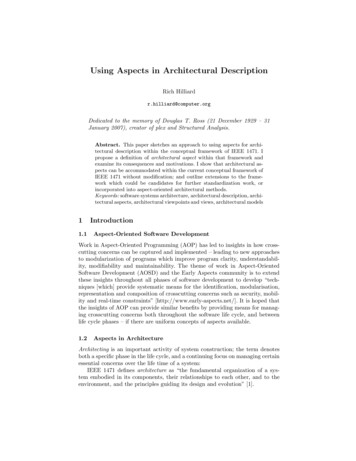
102D. Stewart et al.Fig. 2. AGREE contract for BSCUAssume-Guarantee Reasoning Environment (AGREE) [8] is based on assumeguarantee contracts that can be added to AADL components. The languageused for contract specification is based on the LUSTRE dataflow language [12].The tool allows scaling of formal verification to large systems by splitting theanalysis of a complex system architecture into a collection of verification tasksthat correspond to the structure of the architecture.We use AGREE to specify behavioral contracts corresponding to the behaviors expected of each of the WBS components. An example of a contract is shownin Fig. 2.3Model-Based Safety AnalysisA model-based approach for safety analysis was proposed by Joshi et. al in [14–16]. In this approach, a safety analysis system model (SASM) is the centralartifact in the safety analysis process, and traditional safety analysis artifacts,such as fault trees, are automatically generated by tools that analyze the SASM.The contents and structure of the SASM differ significantly across differentconceptions of MBSA. We can draw distinctions between approaches along several different axes. The first is whether models and notations are purpose-builtfor safety analysis (such as AltaRica [23], smartIflow [13] and xSAP [4]) vs. thosethat extend existing system models (ESM) (HiP-HOPS [6], the AADL errorannex [25]). A second dimension involves the richness of the modeling languagesused to represent failures. Most existing safety analysis languages only supportmodel variables types drawn from small discrete domains (which we call discrete); the xSAP platform is a notable exception that allows rich types. Anotherdimension whether causal or non-causal models are allowed. Non-causal modelsallow simultaneous (in time) bi-directional failure propagations; currently onlyAltaRica [23] and smartIflow [13] allow this. Yet another dimension involves
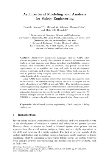
Architectural Modeling and Analysis for Safety Engineering103whether analysis is compositional across layers of hierarchically-composed systems or whole-system.In this section, we will focus on the dimension of failure propagation, andcontrast failure logic modeling (FLM) vs. failure effect modeling (FEM) [19]. InFLM, failures are propagated between components explicitly and the analysisproceeds by determining the likelihood of failures reaching system boundaries.In FEM, failures propagate by changing the system dynamics, which may causethe system behavior to visibly change. Our approach is an extension of AADL(ESM), richly-typed, causal, compositional, mixed FLM/FEM approach. Webelieve this is in a unique area of the trade space compared to other state-ofthe-art MBSA approaches.3.1Failure Logic Modeling (FLM) ApproachesThe FLM approach focuses on faults rather than constructing a model of systemdynamics. We illustrate this approach with the AADL error model annex [25]that can be used to describe system behaviors in the presence of faults. Thisannex has facilities for defining error types which can be used to describe errorevents that indicate faults, errors, and failures in the system (the term erroris used generically in the annex to describe faults, errors, and failures). Thebehavior of system components in the presence of errors is determined by statemachines that are attached to system components; these state machines candetermine error propagations and error composition for systems created fromvarious subcomponents.Error types in this framework are a set of enumeration values such asNoData, BadData, LateDelivery, EarlyDelivery, TimingError, and NoService.These errors can be arranged in a hierarchy. For example, LateDelivery and EarlyDelivery are subtypes of TimingError. The errors do not have any information(other than their type) associated with them. AADL includes information onthe bindings of logical components (processes, threads, systems) and their communication mechanisms onto physical resources (memories, processors, busses),and the error annex uses this information to describe how physical failures canmanifest in logical components.An example is shown in Fig. 3 Errors are labeled with error types: 1-BadData,2-NoData, 3-NoSvc. Failure events that can cause a component to fail are labeledwith the corresponding error number. The error behavior of components isdescribed by their state machines. Note that while all state machines in Fig. 2have two states, they can be much more complex. The dashed arrows indicatepropagations describing how failures in one component can cause other components to fail. For example, failures in the physical layer propagate to failures inthe associated logical components.Although the error model annex is very capable, it is not closely tied to thebehavioral model of components or their requirements. For example, in the wheelbraking system (WBS) example [24], it is possible that hydraulic system valvescan fail open or fail closed. In fail closed, downstream components receive no flowand upstream pipes may become highly pressurized as a natural consequence of
104D. Stewart et al.Fig. 3. Example of error model information and propagationthe failure. Physical models of these behavioral relationships often exist thatcan propagate failures in terms of the behavioral relationships between components. However, with the AADL error model annex, the propagations must be(re)specified and defined for each component. This re-specification can lead toinconsistencies between physical models and error annex models. In addition, thephysical relationships between failures can be complex and may not be describable using enumeration values, leading to additional inconsistencies between thebehavior of the physical phenomena and the behavior of the error model.3.2Failure Effect Modeling (FEM) ApproachesIn a failure effect modeling approach, the analysis starts from a nominal modelof the system that describes the system behavior when no faults are present.To perform safety analysis, we then also formalize the fault model. The faultmodel, in addition to common failure modes such as non-deterministic, inverted,stuck at etc., could encode information regarding fault propagation, simultaneous dependent faults and fault hierarchies, etc. After specifying the fault modeland composing it with the original system model, the safety analysis involvesverifying whether the safety requirements hold in presence of the faults definedin the fault model.In this approach, a safety engineer can model different kinds of fault behavior:e.g., stuck-at, ramp-up, ramp-down, and nondeterministic, and then weave thesefault models into the nominal model. The language for describing faults is extensible, allowing engineers to define a catalog of faults appropriate for their domain.In addition, the weaving process allows error propagation between unconnectedcomponents within a system model [15]. This allows consideration of physicalaspects (e.g., proximity of components, shared resources such as power) thatmay not be present in a logical system model but can lead to dependent failures. In addition, it allows propagation of faults in the reverse direction of themodel data flow. This can occur when physical components have coupling suchas back-pressure in fluid systems or power surges in the opposite direction ofcommunication through connected components. Finally, it is possible to create
Architectural Modeling and Analysis for Safety Engineering105fault mediations to describe the output in the presence of multiple simultaneousfaults.A safety analysis system model can be used for a variety of simulations andanalyses. Modeling allows trivial exploration of what-if scenarios involving combinations of faults through simulations. The current AADL tool suite contains agraphical symbolic simulator that allows for forward and back-stepping throughdifferent failure scenarios. In addition it contains a test-case generator that canautomatically generate such scenarios. For more rigorous analyses, we can usemodel checking tools to automatically prove (or disprove) whether the systemmeets specific safety requirements. As we will demonstrate on the WBS, an engineer first verifies that safety properties hold on the nominal system, an idealizedmodel of the digital controller and the mechanical system containing no faults.Once the nominal model is shown to satisfy the safety property, the behavior ofthe fault-extended model can be examined to examine its resilience to faults.4Architectural Failure Effect Modeling for the WBSWe illustrate our FEM approach on the Wheel Braking System. Starting fromthe nominal model described in Sect. 2.1, we first determine whether a givensafety property of interest holds on a fault-free instance of the model. We thenextend the model with faults and determine whether the property continues tohold under reasonable fault scenarios.The initial safety property to be proven determines whether the system willapply pressure to the wheels when commanded to do so:If pedals are pressed and no skid occurs, then the brakes willreceive pressure.Using the reference AADL model constructed by the SEI [9] extended withAGREE contracts describing system behaviors, this property proves immediately. From this point, we focus our attention on component failures and howthis will affect the top level property of the system.We would like to specify different component failure modes. These failuremodes can be triggered by some internal or propagated fault. In order to triggerthese faults, additional input was added to the AADL model for each fault thatcan occur within a nominal model component. This consists of two types:– fail to fault: This type of fault accounts for both nondeterministic failuresand stuck-at failures. The components that are affected by this fault includemeter valves and pumps. This fault can be used to describe both digital andmechanical errors. Examples of digital failures include a stuck at failure forthe command subsystem in the BSCU component, which causes the commandunit to become stuck at a previous value. An example of a mechanical failurewould be a valve stuck open (or closed).
106D. Stewart et al.– inverted fail fault: This type of fault will be used on components which contain boolean output. It will simply take boolean input, negate it, and outputthe negated value. An example of this is the selector. In the nominal model,input to the selector consists of a boolean value select alternate value fromthe BSCU.These faults can be easily encoded in AGREE as shown in Fig. 4. The failures simply return an alternate value (for fail to) or invert the input value (forinverted failure) when a failure occurs.Fig. 4. AGREE definition of a fail to and inverted failure faultsWhile modeling faults, the duration of the fault must also be taken intoaccount. The AGREE tools allow a great deal of flexibility in terms of howfaults are defined and their duration. For the purposes of this model, we currentlyconsider only transient and permanent faults, where transient faults occur foran instant in time (e.g., a single-event upset) and a permanent fault persists forthe remainder of the system execution.4.1Analysis of Faulty ModelsThe following is a short summary of the failures defined in the fault model.– Valves and Pumps: All valves and pumps have the possibility of a fail to fault.This includes green pump, blue pump, accumulator, and the shutoff valves.– The selector can also have a digital fail to fault regarding the inputs fromBSCU commanding to use normal or alternate means of pressure along withan inverted fail fault which would change the boolean value that commandsantiskid to activate.Given our understanding of the WBS, our assumption was that any singlepermanent fault could be introduced into the system and the pilot would stillbe able to command brake pressure. However, our analysis tools returned acounterexample to the property, and upon examination, the structure of thereference model was insufficient to guarantee the property.The first issue was feedback; the reference model did not have a sensor todetermine pressure after the selector valve. This means that a single failure of(for example) the blue or green antiskid valve cannot be detected by the BSCU(see Fig. 1), and it cannot route around the failure. In order to address this,
Architectural Modeling and Analysis for Safety Engineering107we added a pressure sensor to the wheel that communicates with the BSCU todetect lack of pressure at the wheel.After adding a sensing apparatus to the wheel, the analysis generated anothercounterexample due to a single failure of the selector valve. In the referencemodel, there is a single selector component that takes as inputs the green pump,the blue pump, and the accumulator. A single failure in this component can leadto no pressure along either of the two outgoing pressure lines. To solve this issue,we removed the accumulator from the selector and added an accumulator valve.This component takes in the blue pressure from the selector and the accumulatorpressure. It also takes in a select alternate flag from the BSCU. The output ofthe accumulator valve goes directly to the blue skid component and is either theblue or the accumulator pressure.Finally, our BSCU is currently structured to always fail-over from thegreen system to the blue system but never the reverse. Because of this choice(which matches the AIR6110 document), it is also necessary to guarantee thatselect alternate is false until a failure occurs in the system; otherwise, a singlefailure in the blue anti-skid valve can cause the system to fail to provide pressure.This asymmetry is something that could be revisited in future work.Even after making these three changes to the model, the original propertystill does not prove. At issue is that the sensing of a no-pressure situation isnot instantaneous; there is a delay for this information to reach the BSCU andbe acted upon to switch to the alternate braking system. In our current timingmodel for the system, the feedback to the BSCU involves a delay, but the BSCUand valves can react. Thus, we weaken our top-level property to state that ifthe brakes are pressed for two consecutive time instants, then pressure will beprovided to the wheels:If pedals are pressed in the previous state and pressed in thecurrent state and no skid occurs, then the brakes will receivepressure.The nominal WBS model extended with the faults described in this sectioncan be found at https://github.com/loonwerks/AMASE.5DiscussionWe have used the WBS model as a vehicle to experiment with different modelingand fault representation ideas, and to get a feel for the scalability of our approach.We started from the reference AADL model [9] to attempt to contrast our FEMapproach using AGREE contracts vs. the FLM-based approach that was alreadypart of this model. Part of this was driven by curiosity as to whether importantfaults might be caught by one approach and missed by the other, and to contrastthe two styles of analysis.During the process of defining and injecting faults, subtle issues of the systemstructure and behavioral interactions became much clearer. The idea that the
108D. Stewart et al.system must use the green side until a failure occurs was unexpected. In addition,the extensions to the model were driven by the counterexamples returned by thetools. The approach quickly and precisely provided feedback towards aspectsof the system that were not robust to failure. The researcher who producedthe model (Stewart) was not involved in earlier MBSA work and had no priorexposure to the WBS model and yet was able to relatively quickly construct afault-tolerant model. The fact that these holes in the reference model perhapsmeans that the behavioral approach can be better at drawing attention to certainkinds of failures.On the other hand, the utility of the safety analysis is driven by the “goodness” of the properties. Our one example property is clearly insufficient: forexample, it is not possible to detect faults related to over-pressurization or misapplication of the brakes when no braking is commanded. Of course, any complete analysis should have properties related to each hazardous condition. Theapproach is foundationally a top-down analysis (like fault trees) rather than abottom up approach (like a FMEA/FMECA). In addition, if properties are misspecified, or the system dynamics are incorrectly modeled, then properties mayverify even when systems are unsafe. The explicit propagation approach of theFLM techniques force the analyst to consider each fault interaction. This toois a double-edged sword: when examining some of the fault propagations in thereference model, we disagreed with some of the choices made, particularly withrespect to the selector valve. For example, if no select alternate commands arereceived from the BSCU, then both the green and blue lines emit a No Servicefailure.In terms of scalability, the analysis time for counterexamples was on the orderof 1–2 s, and the time for proofs was around 4 s, even after annotating the modelwith several different failures. From earlier experience applying compositionalverification with the AGREE tools (e.g., [3,21]), we believe that the analysiswill scale well to reasonably large models with many component failures, butthis will be determined in future work.The analysis in this paper involved hand-annotating the models with failurenodes. This process is both schematic and straightforward: we define the AGREEcontracts over internal nominal output variables and then define the actual outputs using the nominal output variables as inputs to the fault nodes like thosein Fig. 4. We are currently in the process of defining a fault integration languagewhich will eliminate the need for hand-annotation. Some aspects of the ErrorAnnex could be directly relevant: the state machines describing leaf-level faultscould easily be compiled into beh
Switching between the hydraulic pistons and pressure sources can be com-manded automatically or manually. If the hydraulic pressure in the green sup-ply is below a certain threshold, there is an automatic switchover to the blue hydraulic supply. If the blue hydraulic pump fails, then the accumulator is used to supply hydraulic pressure.