Transcription
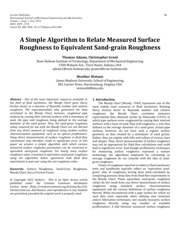
INTERNATIONAL JOURNAL OF MATERIALSVolume 1, 2014How Surface Roughness of Mold CavityInfluence the Material FlowM. Stanek, D. Manas, M. Manas and V. Senkeriktool production. The fluidity of all polymers during injectionmolding cycle is affected by many parameters (mold design,melt temperature, mold temperature, injection rate, pressures,etc.) and by the flow properties of polymers. Results of theexperiments carried out with selected types of polymermaterials proved a minimal influence of surface roughness ofthe runners on the polymer melt flow. This considersexcluding (if the conditions allow it) the very complex andexpensive finishing operations from the technological processas the influence of the surface roughness on the flowcharacteristics does not seem to play as important role as waspreviously thought. A plastic nucleus is formed by this way oflaminar flow, which enables the compression of the melt in themold and consecutive creeping. A constant flowing rate givenby the axial movement of the screw is chosen for most of theflows.Abstract— Delivery of polymer melts into the mold cavity is themost important stage of the injection molding process. This papershows the influence of cavity surface roughness, polymer material(with different flow properties) and technological parameters on theflow length of polymers into mold cavity. Application of themeasurement results may have significant influence on theproduction of shaping parts of the injection molds especially inchanging the so far used processes and substituting them by lesscostly production processes which might increase thecompetitiveness of the tool producers and shorten the time betweenproduct plan and its implementation. Because the finishingoperations of machining are very time and money consuming leadingto high costs of the tool production. Six types of thermoplasticpolymers with different flow properties were tested in this paper.Keywords— injection molding, mold, polymer, roughness,surface, fluidity.wallI. INTRODUCTIONINJECTION molding is one of the most extended polymerprocessing technologies. It enables the manufacture of finalproducts, which do not require any further operations. Thetools used for their production – the injection molds – are verycomplicated assemblies that are made using severaltechnologies and materials. Working of shaping cavities is themajor problem involving not only the cavity of the mold itself,giving the shape and dimensions of the future product, but alsothe flow pathway (runners) leading the polymer melt to theseparate cavities. The runner may be very complex and in mostcases takes up to 40% volume of the product itself (cavity). Inpractice, high quality of runner surface is still very oftenrequired. Hence surface polishing for perfect conditions formelt flow is demanded. The stated finishing operations arevery time and money consuming leading to high costs of themeltflow frontsolidifying layerFig. 1 Fountain flowDuring filling the mold cavity the plastic material does notslide along the steel mold surface but it is rolled over. Thistype of laminar flow is usually described as a “fountain flow”(Fig.1).II. INJECTION MOLDINGThis paper is supported by the internal grant of TBU in Zlin No.IGA/FT/2014/016 funded from the resources of specific university researchand by the European Regional Development Fund under the project CEBIATech No. CZ.1.05/2.1.00/03.0089.Michal Stanek is with the Tomas Bata University in Zlin, nam. T. G.Masaryka 5555, 76001 Zlin, Czech Republic (phone: 420576035153; fax: 420576035176; e-mail: stanek@ft.utb.cz).David Manas is with the Tomas Bata University in Zlin, nam. T. G.Masaryka 5555, 76001 Zlin, Czech Republic (e-mail: dmanas@ft.utb.cz).Miroslav Manas is with the Tomas Bata University in Zlin, nam. T. G.Masaryka 5555, 76001 Zlin, Czech Republic (e-mail: manas@fai.utb.cz).Vojtech Senkerik is with the Tomas Bata University in Zlin, nam. T. G.Masaryka 5555, 76001 Zlin, Czech Republic (e-mail: vsenkerik@ft.utb.cz).ISSN: 2313-0555The testing samples were prepared by injection moldingtechnology (injection molding cycle is shown on Fig. 2). Theinjection mold for was designed for the easiest possiblemanipulation both with the mold itself and during injectionmolding process while changing the testing plates, size of themold gate, pressure and temperature sensors inside the cavity,etc. The cavity space of the mold is generated by the femalemold part, called cavity, and a male mold part, called the core.It is necessary to fill the mold cavity fully during the injectionmolding process. The ability of cavity filling could be affectedby the polymer properties and the properties of cavity walls.55
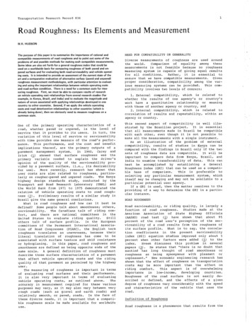
INTERNATIONAL JOURNAL OF MATERIALSVolume 1, 2014a)Fig. 2 Injection molding cycleA.Testing platesThe shaping part of the injection mold is composed of rightand left side. The most important parts of the injection moldconcerning the measurements are: testing plate, cavity plateand a special sprue puller insert. There is possible to usepressure and temperature sensors in the mold cavity for thevalues progress evaluation.b)mold platetesting plateFig. 3 Cross section of mold cavityFig. 4 Injection moldThe cavity (Fig. 4) of testing injection mold for is in a shapeof a spiral (Fig. 5) with the maximum possible length of 2000mm and dimensions of channel cross-section: 6x1 mm. Thecavity is created when the injection mold is closed, i.e. whenshaping plate seals the testing plate in the parting plane of themold. The mold cavity is cooling by flowing oil fromtempering unit. [2]ISSN: 2313-0555a) Left side of injection mold (ejection side)1 – clamping plate, 2, 3 – spacer plate, 4 – cavity plate, 5 – plate,6,7 – ejector plates, 8 – insulating plate, 9 – sprue puller insert,10 – ejector rod, 11 – guide bush,12 – hose nippleb) Right side of injection mold (sprue side)1 – clamping plate, 2 – spacer plate, 3 – testing plate, 4 – plate,5 – insulating plate, 6 – sprue bushing, 7 – guide pillar, 8 – connectorof pressure sensor56
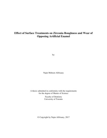
INTERNATIONAL JOURNAL OF MATERIALSVolume 1, 2014Fig. 7 Cavity plate – testing plateFig. 5 Cavity plate – shaping plateThe surface of the plates was machined by four differenttechnologies, which are most commonly used to work downthe cavities of molds and runners in industrial production.These technologies are polishing, grinding, milling and twotypes of electro-spark machining – fine and rough design(Table 1).Table 1 Surfaces of testing platesPlate surfacePolished plate(Ra 0,102µm)Grinded plate(Ra 0,172µm)Electro – sparkmachined plate with a finedesign(Ra 4,055µm)Fig. 6 Testing sample – spiralMilled plate(Ra 4,499µm)Testing Injection mold can operate with 5 easyexchangeable testing plates (Fig. 7) with different surfaceroughness.Electro – sparkmachined plate with a roughdesign(Ra 9,566µm)ISSN: 2313-055557Surface photo
INTERNATIONAL JOURNAL OF MATERIALSVolume 1, 2014 The testing plates are made from tool steel (DIN 1.2325)whose are used for simple and fast changing the surface of themold cavity. [7]Injection molding machine ARBURG Allrounder 420C1000 – 350 with oil tempering unit Regloplas 150 smart wereused for testing samples production.polypropylen filled by 20% of chalk Taboren PH 89T20, MFI 14,4polypropylen filled by 10% of chalk Keltan TP 7603,MFI 16,9 Measurement of Melt Flow Index has been done onextrusion rheometer Kayeness LMI D4003. The principle ofmeasurement consists in polymer melt preparation and itsextrusion. The values of melt temperature and load of ram aredefined in standard. Extruded samples are weighted in definedtime intervals after their cooling. The Melt Flow Index iscalculated from samples weight and from the time interval ofextrusion.B. Sprue puller insertSpecial sprue puller insert enables the exchange ofdifferently sized gates. Size of the gate could be 1, 2, 4 or 6mm.Fig. 7 Sprue puller insertC. Testing injection moldThe testing injection mold is inserted into a universal framewhich was designed for use with many different injectionmolds that fit the size of the frame. This makes the change ofthe separate injection molds easier, because the frame remainsclamped to the injection molding machine and only theshaping and ejection parts of the molds are changed. Attachingright and left sides of the frame to fixed and moving plates ofthe injection molding machine is done using four adjustableclamps on each side. [16, 17]Fig. 8 Melt flow indexer Dynisco Kayeness LMI D4003IV. INJECTION MOLDING OF TESTING SAMPLESIII. TESTED POLYMERSa)Six types of thermoplastic polymers with different flowproperties (MFI - Melt Flow Index) were tested: polypropylen (PP) Mosten GB 003,MFI 3,3polyethylen (LDPE) Bralen VA 20-60,MFI 20termoplastic polyurethan (TPU) Ellastolan C 78 A,MFI 6,1akrylonitril-butadien-styren (ABS) Polylac PA 757,MFI 2,4ISSN: 2313-055558
INTERNATIONAL JOURNAL OF MATERIALSVolume 1, 2014V. INJECTION MOLDING PROCESS SIMULATIONb)A simulation of the injection molding process in SWAutodesk Moldflow Insight 2013 was carried out forcomparison with the reality.c)Fig. 11 Flow length – real sampleFig. 9 Injection molding cyclea) closing the mold, injection of the melt, packing, cooling,b) opening the mold, c) ejection of the testing sampleInjection molding machine ARBURG Allrounder 420Cwith oil tempering unit Regloplas 150 smart were used fortesting samples production.Fig. 12 Flow length – simulationThe same conditions were set as during the actual injectionmolding process. The flow length in the mold cavity of thepolymeric material was observed. The comparison was doneusing only the polished plate, because the SW AutodeskMoldflow Insight does not enable to alter the quality of thesurface cavity. The results from both real injection moldingprocess and simulation prove congruent; see Fig. 10 and Fig.11.Fig. 10 Injection molding machine ARBURG Allrounder 420CISSN: 2313-055559
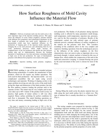
INTERNATIONAL JOURNAL OF MATERIALSVolume 1, 2014VI. RESULTSThe filling of mold cavity depends on material properties,technological conditions and surface quality. The lower is theviscosity of polymer (measured by Melt Flow Index) the bettercavity filling has been achieved (Fig. 12 and Fig. 13).Rising injection rate and filling pressure have a result inbetter in mold cavity filling (Fig. 15) Above mentioned resultsof polymer melt behaviour during mold filling were expected.New and very important result rises from experiments whichanalyzed the influence of surface quality on injection moldfilling. It could be generally said that the surface quality offlow pathway significantly affect flow of polymer melt. It wasfound that better quality of wall surface worsened the flowcondition the length of injected sample spiral was shorter. Thisfinding could have very important effect for tools producers.There is not necessary to use high precision cutting operationand it would be possible to exclude some very costly finaloperation as for example grinding or enKeltanflow length illed ugh")Fig. 13 Influence flow length on surface quality and type of polymer(injection pressure 6 anflow length [mm]200210200injection rate 30 mm/sinjection rate 60 mm/s190injection rate 90 mm/s180170150injection rate 90 mm/s160Keltan100injection rate 60 ion rate 30 mm/smilledelectro-sparkmachined("rough")surface of testing platePolylacFig. 14 Influence of flow length on surface quality and injection rate(Taboren, gate 6 mm, injection pressure 6 MPa)Elastollanelectrospark milled plate 0flow length [mm]flow length [mm]250Fig. 12 Influence of flow length on surface quality and type ofpolymer (injection pressure 8 MPa)200injection pressure 4 MPainjection pressure 6 MPainjection pressure 8 MPa15010050injection pressure 8 MPa0injection pressure 6 ection pressure 4 MPamilledelectro-sparkmachined("rough")surface of testing plateFig. 15 Influence of flow length on surface quality and injectionpressure (Keltan, gate 6 mm, injection rate 30 mm.s-1)ISSN: 2313-055560
INTERNATIONAL JOURNAL OF MATERIALSVolume 1, 2014Table 3 P-values of observed factorsfactorp-valueinjecting rate0,000001injecting pressure0,000000size of gate0,000000surface roughness of testing plate0,291675melt flow index0,000000The following regressive models were found out using the multipleregression.R2 0,943915y t 0,025286 X 1 0,692656 X 2 0,041169 X 3 0,003387 X 4 Fig. 12 Influence of flow length on surface quality and gate size(Keltan, injection pressure 8 MPa, injection rate 90 mm.s-1)0,351107 X 5 ε iwhere:Table 2. Increase of flow length in percentage against the polishedplate for selected h")Mosten- 0,4% 2,3% 3,5% 7,0%Taboren--0,2% 0,6% 3,1% 5,2%VIII. CONCLUSIONThis research looked into the influence of technologicalparameters on filling of the injection mold cavity and the flowlength respectively. The differences in flow lengths at thetesting cavity plates with different surface roughness were verysmall, rather higher in case of rougher surfaces testing platesof the mold.The measurement shows that surface roughness of theinjection mold cavity or runners have no substantial influenceon the length of flow. This can be directly put into practice. Italso suggests that final working and machining (e.g. grindingand polishing) of some parts of the mold, especially theflowing pathways, are not necessary.VII. STATISTICAL EVALUATION OF THE MEASURED DATAThe final statistical evaluation of the measured data wasdone by SW STATISTICA 7. The aim of the statisticalevaluation was to determine the influence of separateparameters on filling the mould cavity by all materials. Due tothe influence of more factors (some independent variables) onthe change of the observed feature (dependent variables),multiple regression was chosen for the description. The resultof the regressive analysis is the regressive model used topredict the value of dependent variable at a given value ofindependent variable.The dependent variable is the flow length. We observe theinfluence of five independent variables (injecting pressure,injecting rate, size of the gate, surface roughness of the testingplates and Melt Flow Index of the materials) on the flowlength.To find out the impact of the factors on flow length, thedispersion analysis was carried out. The analysis was doneseparately for every material group (thermoplastics,thermoplastic elastomers and elastomers) The resulting pvalues are stated in Table 3. The values under p 0,05 arestatistically relevant.ISSN: 2313-0555yt – flow lengthX1 – injection rateX2 – injection pressureX3 – size of gateX4 – surface roughness of testing plateX5 – melt flow indexεi – incidental valuesACKNOWLEDGMENTThis paper is supported by the internal grant of TBU in ZlinNo. IGA/FT/2014/016 funded from the resources of specificuniversity research and by the European RegionalDevelopment Fund under the project CEBIA-Tech No.CZ.1.05/2.1.00/03.61
INTERNATIONAL JOURNAL OF MATERIALSVolume 1, 12][13][14][15][16][17][18][19][20][21][22]D. Manas, M. Hribova, M. Manas, M. Ovsik, M. Stanek, D. Samek,“The effect of beta irradiation on morfology and micro hardness ofpolypropylene thin layers“, 2012, Thin Solid Films, Volume 530, pp.49-52. ISSN 0040-6090.M. Stanek, D. Manas, M. Manas, O. Suba, “Optimization of InjectionMolding Process“, International Journal of Mathematics andComputers in Simulation, Volume 5, Issue 5, 2011, p. 413-421M. Stanek, D. Manas, M. Manas, J. Javorik, “Simulation of InjectionMolding Process by Cadmould Rubber“, International Journal ofMathematics and Computers in Simulation, Volume 5, Issue 5, 2011, p.422-429D. Manas, M. Manas, M. Stanek, S. Sanda, V. Pata, “Thermal Effectson Steels at Different Methods of Separation“, 2011, Chemicke listy,Volume 105, Issue 17, pp. S713-S715M. Manas, D. Manas, M. Stanek, S. Sanda, V. Pata, “Improvement ofMechanical Properties of the TPE by Irradiation“, 2011, Chemicke listy,Volume 105, Issue 17, pp. S828-S829J. Javorik, J., M. Stanek, “The Shape Optimization of the PneumaticValve Diaphragms“, International Journal of Mathematics andComputers in Simulation, Volume 5, Issue 4, 2011, p. 361-369Stanek, M, Manas, M., Manas, D., Sanda, S., “Influence of SurfaceRoughness on Fluidity of Thermoplastics Materials”, Chemicke listy,Volume 103, 2009, pp.91-95Manas, D., Stanek, M., Manas, M., Pata V., Javorik, J., “Influence ofMechanical Properties on Wear of Heavily Stressed Rubber Parts”, KGK– Kautschuk Gummi Kunststoffe, 62. Jahrgang, 2009, p.240-245Stanek, M., Manas, M., Manas, D., Sanda, S., “Influence of SurfaceRoughness on Fluidity of Thermoplastics Materials”, Chemicke listy,Volume 103, 2009, p.91-95Stanek, M., Manas, M., Manas, D., “Mold Cavity Roughness vs. Flowof Polymer”, Novel Trends in Rheology III, AIP, 2009, pp.75-85J. Javorik, M. Stanek, “The Numerical Simulation of the RubberDiaphragm Behavior,” in Proc. 13th WSEAS International Conferenceon Automatic Control, Modelling & Simulation, Lanzarote, Spain,2011, pp. 117-120.J. Javorik, D. Manas, “The Specimen Optimization for the EquibiaxialTest of Elastomers,” in Proc. 13th WSEAS International Conference onAutomatic Control, Modelling & Simulation, Lanzarote, Spain, 2011,pp. 121-124.M. Stanek, D. Manas, M. Manas, O. Suba, “Optimization of InjectionMolding Process by MPX,” in Proc. 13th WSEAS InternationalConference on Automatic Control, Modelling & Simulation, p.212-216.M. Manas, M. Stanek, D. Manas, M. Danek, Z. Holik, “Modification ofpolyamides properties by irradiation”, Chemické listy, Volume 103,2009, p.24-26.D. Manas, M. Manas, M. Stanek, M. Zaludek, S. Sanda, J. Javorik, V.Pata, “Wear of Multipurpose Tire Treads” Chemické listy, Volume 103,2009, p.72-74.S. Sanda, M. Manas, M. Stanek, D. Manas, L. “Rozkosny, InjectionMold Cooling System by DMLS”, Chemicke listy, Volume 103, 2009,p.140-142.M. Stanek, M. Manas, T. Drga, D. Manas, “Testing Injection Molds forPolymer Fluidity Evaluation”, 17th DAAAM International Symposium:Intelligent Manufacturing & Automation: Focus on Mechatronics andRobotics, Vienna, Austria, 2006, p.397-398.M. Stanek, M. Manas, D. Manas, S. Sanda, “Influence of SurfaceRoughness on Fluidity of Thermoplastics Materials, Chemické listy,Volume 103, 2009, p.91-95M. Manas, M. Stanek, D. Manas, M. Danek, Z. Holik, ”Modification ofpolyamides properties by irradiation”, Chemické listy, Volume 103,2009, p.24-28Manas, D., Stanek, M., Manas, M., Pata V., Javorik, J., “Influence ofMechanical Properties on Wear of Heavily Stressed Rubber Parts”, KGK– Kautschuk Gummi Kunststoffe, 62. Jahrgang, 2009, p.240-245.J. Javorik, D. Manas, “The Specimen Optimization for the EquibiaxialTest of Elastomers,” in Proc. 13th WSEAS International Conference onAutomatic Control, Modelling & Simulation, Lanzarote, Spain, 2011,pp. 121-124.M. Stanek, D. Manas, M. Manas, J. Javorik, “Simulation of InjectionMolding Process by Cadmould Rubber“, International Journal ofISSN: cs and Computers in Simulation, Volume 5, Issue 5, 2011, p.422-429.V. Pata, D. Manas, M. Manas, M. Stanek, “Visulation of the Wear Testof Rubber Materials”, Chemicke listy, Volume 105, 2011, pp.290-292.M. Adamek, M. Matysek, P. Neumann, “Modeling of the MicroflowSenzor”, in Proc. 13th WSEAS International Conference on AutomaticControl, Modelling & Simulation, Lanzarote, Canary Islands, 2011,p.137-140.M. Stanek, D. Manas, M. Manas, O. Suba, “Optimization of InjectionMolding Process by MPX,” in Proc. 13th WSEAS InternationalConference on Automatic Control, Modelling & Simulation, p.212-216.Manas, M.; Manas, D.; Stanek, M.; Mizera, A.; Ovsik, M. Modificationof polymer properties by irradiation properties of thermoplasticelastomer after radiation cross-linking. Asian Journal of Chemistry,2013, Volume 25, Issue 9, s. 5124-5128. ISSN 09707077.Ovsik, M., Manas, D., Manas, M., Stanek, M., Kyas, K., Bednarik, M.,Mizera, A. “Microhardness of HDPE influenced by Beta Irradiation“,International Journal of Mathematics and Computers in Simulation,Volume 6, Issue 6, 2012, p. 566-574, ISSN 1998-0159.T. Sysala, O. Vrzal, “A Real Models Laboratory and an Elevator ModelControlled through Programmable Controller (PLC)”, in Proc. 13thWSEAS International Conference on Automatic Control, Modelling &Simulation, Lanzarote, Canary Islands, 2011, p.365-368.Stanek, M., Manas, M., Manas, D., “Mold Cavity Roughness vs. Flowof Polymer”, Novel Trends in Rheology III, AIP, 2009, pp.75-85.F. Hruska, “Project of Control System of Thermal Comfort”, in Proc.13th WSEAS International Conference on Automatic Control,Modelling & Simulation, Lanzarote, Canary Islands, 2011, p.96-100.O. Suba, L. Sykorova, S. Sanda, M. Stanek “Modelling of ThermalStresses in Printed Circuit Boards”, in Proc. 13th WSEAS InternationalConference on Automatic Control, Modelling & Simulation, Lanzarote,Canary Islands, 2011, p.173-175.O. Suba, L. Sykorova, S. Sanda, M. Stanek, “Stress – State Modelling ofInjection-molded Cylindrical Bosses Reinforced with Short Fibres”, inProc. 13th WSEAS International Conference on Automatic Control,Modelling & Simulation, Lanzarote, Canary Islands, 2011, p.177-179.T. Sysala, O. Vrzal, “A Real Models Laboratory and an Elevator ModelControlled through Programmable Controller (PLC)”, in Proc. 13thWSEAS International Conference on Automatic Control, Modelling &Simulation, Lanzarote, Canary Islands, 2011, p.365-368.V. Pata, D. Manas, M. Manas, M. Stanek, “Visulation of the Wear Testof Rubber Materials”, Chemicke listy, Volume 105, 2011, pp.290-292L. Pekar, R. Matusu, P. Dostalek, J. Dolinay, “The Nyquist criterion forLTI Time-Delay Systems”, in Proc. 13th WSEAS InternationalConference on Automatic Control, Modelling & Simulation, Lanzarote,Canary Islands, 2011, p.80-83.L. Pekar, R. Prokop, “Analysis of a Simple Quasipolynomial of DegreeOne”, in Proc. 13th WSEAS International Conference on AutomaticControl, Modelling & Simulation, Lanzarote, Canary Islands, 2011,p.86-89.M. Stanek, M. Manas, D. Manas, “Mold Cavity Roughness vs. Flow ofPolymer”, Novel Trends in Rheology III, AIP, 2009, pp.75-85.K. Kyas, M. Stanek, J. Navratil, M. Manas, D. Manas, V. Senkerik, A.Skrobak, “Rubberproduct properties influenced by runnerstrajectory”, International Journal of Mathematics and Computers inSimulation 7 (1) , pp. 1-8.J. Cerny, D. Manas, Z. Holik, M. Ovsik, M. Bednarik, A. Mizera, M.Stanek, M. Manas, “Wear of heavy industry tires”, International Journalof Mathematics and Computers in Simulation 7 (1) , pp. 9-16J. Cerny, D. Manas, Z. Holik, M. Ovsik, M. Bednarik, A. Mizera, M.Manas, M. Stanek, “Methods of design of ergonomics parts”,International Journal of Mathematics and Computers in Simulation 7(1), pp. 17-24M. Stanek, D. Manas, M. Manas, J. Navratil, K. Kyas, V. Senkerik, A.Skrobak, “Comparison of different rapid prototyping methods”,International Journal of Mathematics and Computers in Simulation 6(6), pp. 550-557K. Kyas, J. Cerny, M. Stanek, M. Manas, D. Manas, V. Senkerik, A.Skrobak, “Measuring of temperature and pressure in injection mold”,International Journal of Mathematics and Computers in Simulation 6(6), pp. 600-607
pressure and temperature sensors in the mold cavity for the values progress evaluation. testing plate. Fig. 3 Cross section of mold cavity . The cavity (Fig. 4) of testing injection mold for is in a shape of a spiral (Fig. 5) with the maximum possible length of 2000 mm and dimensions of channel cross-section: 6x1 mm. The