Transcription
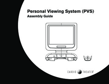
Personal Viewing System (PVS)Assembly Guide
Important Safety InstructionsWhen using exercise equipment, basic precautions should always betaken, including the following:Read all instructions before using the Personal Viewing System(PVS). These instructions are written for your safety and to protectthe equipment. Use the PVS only for its intended purpose. Do not use accessoryattachments that are not recommended by the manufacturer, assuch attachments might cause injuries. Always check the PVS and exercise equipment before each use.Make sure that all fasteners and cables are secure and in goodworking condition.Important: The important safety instructions written here reflect aportion of what is found in the Precor Product Owner’s Manuals andUser’s Reference Guides. Please review and follow the safetyinstructions found there. If you do not assemble the PVS EntertainmentOption according to these instructions, you could void the LimitedWarranty.Radio Frequency Interference (RFI)Federal Communications Commission, Part 15WARNING: To prevent fire or electrical shock, do not expose thisequipment to rain, moisture or excess heat.The unit has been tested and found to comply with the limits for Part 15of the FCC Rules. These limits are designed to provide reasonableprotection against harmful interference when the equipment is operatedin a commercial environment.PVS Assembly Guide: Important Safety InstructionsHowever, there is no guarantee that interference will not occur in aparticular installation. If the unit does cause harmful interference to radioor television reception, which can be determined by turning theequipment off and on, the user is encouraged to try to correct theinterference by one or more of the following measures: Reorient or relocate the receiving antenna. Increase the separation between the equipment and the receiver. Connect the equipment into a separate outlet that uses a differentcircuit than the receiver.Consult a Cardio Theater or an experienced radio/TV technician forhelp.WARNING: Per FCC rules, changes or modifications not expresslyapproved by Cardio Theater could void the user’s authority tooperate the equipment.Canadian Department of CommunicationsThe equipment does not exceed the Class A limits for radio noiseemissions from a digital apparatus set out in the Radio InterferenceRegulations of the Canadian Department of Communications.Le présent appareil numérique n’émet pas de bruitsradioéélectriques dépassant les limites applicables aux appareilsnumériques de la class A prescrites dans le Règlement sur lebrouillage radioélectrique édicté par le ministére desCommunications du Canada.IMPORTANT SAFETY INSTRUCTIONS The equipment generates, uses, and can radiate radio frequency energyand, if not installed and used in accordance with the assembly,installation and maintenance instruction manuals, may cause harmfulinterference to radio communications.1
Table of ContentsImportant Safety Instructions .1Radio Frequency Interference (RFI) .1Federal Communications Commission, Part 15 . 1Canadian Department of Communications . 1Precor EFX Assembly Steps . 12Install the Cables .13Attach the Entertainment Option .15Install the Screen .17Test the PVS .18Before You Begin .3Review Precor Equipment Assembly Instructions . 3Installation Requirements . 3Unpacking the Equipment . 3Required Tools . 3Obtaining Service . 4Precor Treadmill Assembly Steps . 19Install the Cables and Bracket .20Attach the Entertainment Option .21Install the Screen .22Install the Headphone .23Test the PVS .24Precor Climber Assembly Steps .5Install the Cables . 6Attach the Entertainment Option . 8Install the Screen .10Test the PVS .11Precor Cycle Assembly Steps . 25Install the Cables .26Attach the Entertainment Option .27Install the Screen .29Test the PVS .30PVS Assembly Guide: Table of Contents2
Before You BeginThank you for adding the Personal Viewing System (PVS) to your Precorpurchase. For proper installation, please read this guide thoroughly andfollow the assembly instructions.Important: If you have designed the club facility layout with the PVS inmind, the following instructions provide what you need to integrate thePrecor unit with the PVS assembly.Review Precor Equipment Assembly InstructionsIf the PVS Entertainment Option and the Precor units are to be assembledon the same day, be sure to review the Precor assembly instructions thataccompany each unit. Alleviate additional assembly or disassembly steps bycombining the PVS and Precor unit assemblies as needed.Installation RequirementsReview these installation requirements before assembly: Provide ample space around the unit. Open space around the unitallows for easier access and installation. Open the box and assemble components in the sequence presented inthis guide. Refer to both assembly guides that accompany the PVSEntertainment Option and the Precor unit.Unpacking the EquipmentThe PVS Entertainment Option is shipped in one box with the followingitems: Screen Bracket Eight black buttonhead screws Integrated controller (5-wire, stereo plug, and RJ45 cables attached) Transition cover Headphone jack Fifteen foot coaxial/power cable (audio/video and power cable) Power module and extension cableIf any items are missing, contact the dealer from whom you purchased theunit or contact Cardio Theater Technical Support.Required Tools Standard set of hex keys Phillips-head screwdriver Read all the instructions on each page. Flathead screwdriver (treadmill assembly only) While you may be able to assemble the PVS Entertainment Optionusing the illustrations only, important safety notes and other tips areincluded in the text. Some illustrations show a generic view because ofthe similar assemblies across several Precor products. Needle nose pliers Roll of electrical tape Step stoolThe assembly of the PVS Entertainment Option takes about ½ hour tocomplete.PVS Assembly Guide: Before You Begin3
Obtaining ServiceFor information about product operation or service, refer to the CardioTheater web site at www.cardiotheater.com or contact an authorized CardioTheater Technical Support Representative at 1-800-776-6695 orservice@cardiotheater.com. Representatives are available to serve you from6:00 am to 5:00 pm, Monday through Friday, U.S.A. Pacific Time.Should you need more information regarding customer support numbers forPrecor equipment, or a list of authorized service centers, visit the Precor website at www.precor.com/corp/contact.Returning Equipment to Cardio TheaterTo return equipment to Cardio Theater for any reason, you must contactCardio Theater Technical Support and obtain a return authorization (RMA)number. When requesting the RMA number, explain why you are returningthe equipment, for example you ordered too many controllers and the extracontroller can be returned to stock, or the equipment needs repairs.Important: Equipment must be shipped with an RMA number in order forCardio Theater to process it. Any equipment received without an RMAnumber will be returned to the sender.PVS Assembly Guide: Before You Begin4
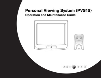
Precor Climber Assembly StepsTo expose the wiring and connections inside the display console andinstall the PVS, you need to take the following steps:Use a Phillips-head screwdriver to remove the one screw that securesthe neck cover and the four screws that secure the back consoleplate. Set the fasteners, neck cover, and back console plate aside.Remove the entertainment option cover. Tabs exist on either side ofthe cover. Press the tabs to release the cover. You can discard theentertainment option cover.Important: If you are replacing the integrated receiver, disconnectthe 5-wire cable from the display console, and then pull the stereoplug (audio cable) out of the cover before removing and discardingthe cover.At the base of the display console, remove the audio cover. Place afinger inside the audio cover to push it out of the display console. Youcan discard the audio cover because it is replaced with theheadphone jack.Slide the rubber grommet and the plastic top cover along the uprightsupport to expose the hole that the existing RJ45 cable feeds through.Rubber grommetNote: Push the rear tab in on the plastic top cover to unlock it beforelifting it. You may need to detach the rubber grommet from the plastictop cover before sliding both along the upright support.Rear tabPVS Assembly Guide: Precor Climber Assembly Steps5
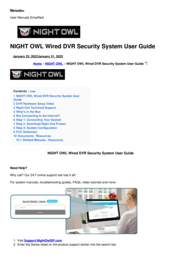
Install the CablesTo make it easier to feed the cables through the unit, tape the ends ofthe cables together (the female coaxial connection to the powercable). Refer to the illustration.CAUTION: Be careful that you do not jostle or damage the heart rateelectronics board on the inside of the display console. Cableconnections can become dislodged which will impair the heart rateand upper display functions.Feed the taped cable ends through the top of the display console andcontinue to feed the taped cable ends through the neck tube.Note: Leave about 1 foot (30 cm) of cables hanging out of the upperportion of the display console. The coaxial and power connections willbe attached to the back of the screen.Important: Make sure that the cables are not pinched between thebracket and the display console.PVS Assembly Guide: Precor Climber Assembly Steps6
Continue to feed the taped cables down through the upright support,following the same route as the existing RJ45 cable.Pull the taped cables out of the hole at the base of the upright.Note: You may need to use needle nose pliers to gently pull the cableconnectors out the small opening.Feed the taped cables and its connectors into the internal uprightframe tube and out onto the floor.Note: You may need to ask for assistance to tip the unit on its side.Obtaining assistance and slightly tipping the unit may make it easierto gain access to the cables.Pull the taped cables out from the base of the unit.PVS Assembly Guide: Precor Climber Assembly Steps7
Attach the Entertainment OptionCAUTION: Do not try to access the tab found beneath the heart rateelectronics board.Separate the display console face from the console. Start at the topand work toward the bottom, pressing the five tabs to release it. Thisprovides easier access to the 5-pin connector.Hold the integrated controller above the display console and feed theaudio cable through the opening in the base of the display console.Let the audio cable hang loose.Top two tabsCAUTION: It is critical that you attach the red wire on the 5-wireentertainment option cable to Pin 1. The word, PIN 1, is inscribed onthe back of the display console. An arrow points to the location ofPin 1. The connector is keyed so it will only connect one way. Do notforce the connection.Connect the 5-wire entertainment option cable to the display console.Reattach the display console face by aligning the tabs and applyingpressure to the display face.Install the integrated controller by aligning the two tabs and applyingpressure. Arrange the cables so you do not inadvertently pinch ordamage the cables.Important: Cable damaged by improper installation will not becovered by the Limited Warranty.PVS Assembly Guide: Precor Climber Assembly Steps8
Feed the audio cable through the base of the display console andattach it to the headphone jack.Insert the headphone jack into the base of the display console. Snapthe headphone jack into place by positioning the rear tab first, andthen applying pressure to the base.Hold the cables out of the way as you slide the bracket into positionand align the four mounting holes. Insert four black buttonheadscrews and wrench tighten using a ⁵ ₃₂-inch hex key.Attach the transition cover. Insert the base of the cover first and applypressure to the upper portion. It should easily snap it into place.PVS Assembly Guide: Precor Climber Assembly Steps9
Install the ScreenPlace the screen face down on a clean work surface so you have easyaccess to the back plate. Use a Phillips-head screwdriver to removethe one screw on the back plate.Place your fingers in the finger tabs on opposite sides of the backplate and pull up to remove the back plate. Set the fastener and backplate aside.Move the cables out of the way as you attach the screen to thebracket using four buttonhead screws. Finger tighten and thenwrench tighten using a ⁵ ₃₂-inch hex key.Plug the RJ45 cable into the back of the screen. Feed the coaxialcable between the back of the screen and the bracket. Connect boththe power and coaxial cables to the proper receptacles. Turn the endsof the coaxial and power connectors to properly secure the cables.Replace the back plate. Insert the base tabs first and then, applypressure to engage the side tabs. Replace the Phillips-head screw.Refer to the illustration for step 20.Note: You may want to test the PVS before replacing the back plate.In this case, perform steps 26 and 27 and then return to steps 24 and25 to complete the PVS assembly.Reassemble the display console by using a Phillips-head screwdriverto reattach the back console plate (four screws) and neck cover (onescrew) removed in step 1. Refer to the illustration for step 1.PVS Assembly Guide: Precor Climber Assembly Steps10
Test the PVSAt the base of the climber, plug the power cable in to the powerextension module and connect it, along with the coaxial cable, into theappropriate Cardio Theater equipment connections.Observe whether the PVS (screen and integrated controller) isreceiving power while you configure the channels using the integratedcontroller and check the audio connection. For instructions on how toconfigure channels and troubleshoot the PVS, refer to the PVSOperation and Maintenance Guide provided in the box.Note: A green LED illuminates on the integrated controller when it isconnected to a power source.PVS Assembly Guide: Precor Climber Assembly Steps11
Precor EFX Assembly StepsTo expose the wiring and connections inside the display console andinstall the PVS, you need to take the following steps:Use a Phillips-head screwdriver to remove the eight screws thatsecure the front and back neck covers. Set the fasteners and coversaside.Remove the four screws that secure the back console plate. Set thefasteners and back console plate aside.Remove the entertainment option cover. Tabs exist on either side ofthe cover. Press the tabs to release the cover. You can discard theentertainment option cover.Important: If you are replacing the integrated receiver, disconnectthe 5-wire cable from the display console, and then pull the stereoplug (audio cable) out of the cover before removing and discardingthe cover.At the base of the display console, remove the audio cover. Place afinger inside the audio cover to push it out of the display console. Youcan discard the audio cover because it is replaced with theheadphone jack.PVS Assembly Guide: Precor EFX Assembly Steps12
Install the CablesTo make it easier to feed the cables through the unit, tape the ends ofthe cables together (the female coaxial connection to the powercable). Refer to the illustration.Loosen the display console from its bracket by removing the twobottom buttonhead screws using a ⁵ ₃₂-inch hex key. This providesaccess to the EFX neck tube. Set the fasteners aside.CAUTION: Do not lift the base of the display console too much oryou may inadvertently break the upper tabs or damage the displayconsole. Be careful that you do not jostle or damage the heart rateelectronics board on the inside of the display console. Cableconnections can become dislodged which will impair the heart rateand upper display functions.Feed the taped cable ends through the top of the console. Lift thebase of the display console and continue to feed the taped cableends through the neck tube. Let the cables hang.Note: Leave about 1 foot (30 cm) of cables hanging out of the upperportion of the display console. The coaxial and power connections willbe attached to the back of the screen.Reattach the display console by inserting the two buttonhead screwsremoved in step 6 and wrench tighten. Refer to the illustration forstep 6.Important: Make sure that the cables are not pinched between thebracket and the display console.Neck tubePVS Assembly Guide: Precor EFX Assembly Steps13
Remove the two Phillips-head screws that secure the upper boot.Slide the upper boot along the upright support and tape it into place.Refer to the illustration.Feed the taped cables back up through the neck tube and out theside hole. Refer to the illustration. Continue to feed the taped cablesdown through the upright support, following the same route as theexisting RJ45 cable.NecktubePull the taped cables out of the opening near the base of the unit, andthen feed them back through the same opening. Continue feeding thetaped cables through the small opening in the lower boot and ontothe floor.Note: You may need to use needle nose pliers to gently pull the cableconnectors out the small opening.Note: This view shows the EFX556i.The location of the cables is thesame for all EFX units.PVS Assembly Guide: Precor EFX Assembly Steps14
Attach the Entertainment OptionCAUTION: Do not try to access the tab found beneath the heart rateelectronics board.Separate the display console face from the console. Start at the topand work toward the bottom, pressing the five tabs to release it. Thisprovides easier access to the 5-pin connector.Hold the integrated controller above the display console and feed theaudio cable through the opening in the base of the display console.Let the audio cable hang loose.Top two tabs firstCAUTION: It is critical that you attach the red wire on the 5-wireentertainment option cable to Pin 1. The word, PIN 1, is inscribed onthe back of the display console. An arrow points to the location ofPin 1. The connector is keyed so it will only connect one way. Do notforce the connection.Connect the 5-wire entertainment option cable to the display console.Reattach the display console face by aligning the tabs and applyingpressure to the display face.Install the integrated controller by aligning the two tabs and applyingpressure. Arrange the cables so you do not inadvertently pinch ordamage the cables.Important: Cable damaged by improper installation will not becovered by the Limited Warranty.PVS Assembly Guide: Precor EFX Assembly Steps15
Feed the audio cable through the base of the display console andattach it to the headphone jack.Insert the headphone jack into the base of the display console. Snapthe headphone jack into place by positioning the rear tab first, andthen applying pressure to the base.Hold the cables out of the way as you slide the bracket into positionand align the four mounting holes. Insert four black buttonheadscrews and wrench tighten using a ⁵ ₃₂-inch hex key.Attach the transition cover. Insert the base of the cover first and applypressure to the upper portion. It should easily snap it into place.PVS Assembly Guide: Precor EFX Assembly Steps16
Install the ScreenPlace the screen face down on a clean work surface so you have easyaccess to the back plate. Use a Phillips-head screwdriver to removethe one screw on the back plate.Place your fingers in the finger tabs on opposite sides of the backplate and pull up to remove the back plate. Set the fastener and backplate aside.Move the cables out of the way as you attach the screen to thebracket using four buttonhead screws. Finger tighten and thenwrench tighten using a ⁵ ₃₂-inch hex key.Plug the RJ45 cable into the back of the screen. Feed the coaxialcable between the back of the screen and the bracket. Connect boththe power and coaxial cables to the proper receptacles. Turn the endsof the coaxial and power connectors to properly secure the cables.Replace the back plate. Insert the base tabs first and then, applypressure to engage the side tabs. Replace the Phillips-head screw.Refer to the illustration for step 21.Note: You may want to test the PVS before replacing the back plate.In this case, perform steps 27 and 28 and then return to steps 25 and26 to complete the PVS assembly.Reassemble the display console by using a Phillips-head screwdriverto reattach the front and back covers (eight screws) and reinstall theback console plate (four screws) removed in steps 1 and 2. Refer tothe illustrations shown for steps 1 and 2.PVS Assembly Guide: Precor EFX Assembly Steps17
Test the PVSAt the base of the EFX, plug the power cable to the power extensionmodule and connect it, along with the coaxial cable, into the stripprovided for Cardio Theater equipment.Observe whether the PVS (screen and integrated controller) isreceiving power while you configure the channels using the integratedcontroller and check the audio connection. For instructions on how toconfigure channels and troubleshoot the PVS, refer to the PVSOperation and Maintenance Guide provided in the box.Note: A green LED illuminates on the integrated controller when it isconnected to a power source.PVS Assembly Guide: Precor EFX Assembly Steps18
Precor Treadmill Assembly StepsTo expose the wiring and connections inside the display console andinstall the PVS, you need to take the following steps:CAUTION: Turn OFF the treadmill and unplug it. The ON/OFF (I/O)switch is located on the front of the treadmill beneath the hoodoverhang.Important: Unplug any RJ45 connections from the back of thedisplay console cover before removing the cover.Use a Phillips-head screwdriver to remove the nine screws thatsecure the display console back cover. Set the fasteners aside.To remove the display console back cover, pull in on one side as youpull the cover down toward the floor. This should flex the cover andenable you to slide it past the fasteners on the upright support.Remove the entertainment option cover. Tabs exist on either side ofthe cover. Press the tabs to release the cover. You can discard theentertainment option cover.Important: If you are replacing the integrated receiver, disconnectthe 5-wire cable from the display console, and then pull the stereoplug (audio cable) out of the cover before removing and discardingthe cover.At the base of the display console back cover, remove the break awaypiece to allow room for the audio cable. Use a flathead screwdriver topush the piece out of the display console back cover. You can discardthe break away piece.PVS Assembly Guide: Precor Treadmill Assembly Steps19
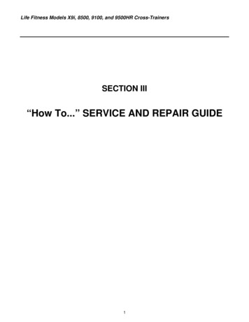
Install the Cables and BracketTo make it easier to feed the cables through the unit, tape the ends ofthe cables together (the female coaxial connection to the powercable). Refer to the illustration.STOPbuttonhousing.Feed the taped cables through the large, rectangular opening at thetop of the display console. Continue to feed the taped cables downthrough the upright support, following the same route as the existingRJ45 cable.Note: Leave about 1 foot (30 cm) of cables hanging out of the upperportion of the display console. The coaxial and power connections willbe attached to the back of the screen.Pull the taped cables out of the base of the upright support and ontothe floor.CAUTION: Be careful as you slide the bracket into position and alignthe mounting holes. Avoid sliding the bracket into the STOP buttonhousing as damage can occur to the electronics board.BracketHold the cables out of the way as you slide the bracket into positionand align the two back and two side mounting holes. Insert four blackbuttonhead screws and wrench tighten using a ⁵ ₃₂-inch hex key.CAUTION: Avoid touching the heart rate cable or the heart rateelectronics board. Cable connections can become dislodged whichwill impair the heart rate and upper display functions. Use the bullnosed portion of the hex key to tighten the side fasteners.Heart rateelectronicsboard.PVS Assembly Guide: Precor Treadmill Assembly Steps20
Top two tabsAttach the Entertainment OptionCAUTION: Do not try to access the tab found beneath the heart rateelectronics board.Separate the display console face from the console. Start at the topand work toward the bottom, pressing the five tabs to release it. Thisprovides easier access to the 5-pin connector.Hold the integrated controller above the display console and feed theaudio cable through the opening in the base of the display console.Let the audio cable hang loose.CAUTION: It is critical that you attach the red wire on the 5-wireentertainment option cable to Pin 1. The word, PIN 1, is inscribed onthe back of the display console. An arrow points to the location ofPin 1. The connector is keyed so it will only connect one way. Do notforce the connection.Connect the 5-wire entertainment option cable to the display console.Reattach the display console face by aligning the tabs and applyingpressure to the display face.Important: Rest the integrated controller on top of the displayconsole while you realign the cables and install the transition cover.The transition cover must be installed before you can attach theintegrated controller.Attach the transition cover by inserting the base of the cover first andthen applying pressure to the upper portion. It should snap easily intoplace.Install the integrated controller by aligning the two tabs and applyingpressure. Arrange the cables so you do not inadvertently pinch ordamage the cables.Important: Cable damaged by improper installation will not becovered by the Limited Warranty.PVS Assembly Guide: Precor Treadmill Assembly Steps21
Install the ScreenPlace the screen face down on a clean work surface so you have easyaccess to the back plate. Use a Phillips-head screwdriver to remove theone screw on the back plate.Place your fingers in the finger tabs on opposite sides of the back plateand pull up to remove the back plate. Set the fastener and back plateaside.Move the cables out of the way as you attach the screen to the bracketusing four buttonhead screws. Finger tighten and then wrench tightenusing a ⁵ ₃₂-inch hex key.Plug the RJ45 cable into the back of the screen. Feed the coaxial cablebetween the back of the screen and the bracket. Connect both thepower and coaxial cables to the proper receptacles. Turn the ends ofthe coaxial and power connectors to properly secure the cables.PVS Assembly Guide: Precor Treadmill Assembly Steps22
Install the HeadphoneFeed the audio cable through the break out in the display consolecover.Replace the display console back cover by positioning one sideabove the upright support fasteners. Pull in on the other side to flexthe cover which allows you to push it up and slide it past the fastenerson the upright support.Use a flat head screwdriver to slide the display console cover underthe top console cover.Use a Phillips-head screwdriver to reattach the display console backcover with the nine fasteners removed in step 1. Refer to theillustration for step 1.Attach the stereo plug to the headphone jack.Insert the headphone jack into the base of the display console. Snapthe headphone jack into place by positioning the rear tab first, andthen applying pressure to the base.Replace the back plate. Insert the base tabs first, and then applypressure to engage the side tabs. Replace the Phillips-head screw.Refer to the illustration for step 15.Note: You may want to test the PVS before replacing the back plate.PVS Assembly Guide: Precor Treadmill Assembly Steps23
Test the PVSAt the base of the treadmill, plug the power cable into the powerextension module and connect it, along with the coaxial cable, into thestrip provided for Cardio Theater equipment.Observe whether the PVS (screen and integrated controller) isreceiving power while you configure the channels using the integratedcontroller and check the audio connection. For instructions on how toconfigure channels and troubleshoot the PVS, refer to the PVSOperation and Maintenance Guide provided in the box.Note: A green LED illuminates on the integrated controller when it isconnected to a power source.PVS Assembly Guide: Precor Treadmill Assembly Steps24
Precor Cycle Assembly StepsTo expose the wiring and connections inside the display console andinstall the PVS, you need to take the following steps:Use a Phillips-head screwdriver to remove the four screws that securethe back
† Headphone jack † Fifteen foot coaxial/power cable (audio/video and power cable) † Power module and extension cable If any items are missing, contact the dealer from whom you purchased the unit or contact Cardio Theater Technical Support. Required Tools s y e k x e h f o t e s d r a d n a t †S † Phillips-head screwdriver