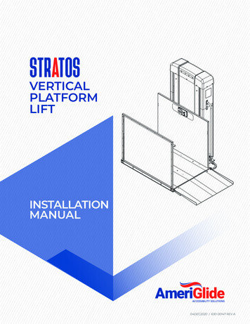
Transcription
2020 630-00147 REV A
STRATOSTABLE OF CONTENTSTABLE OF CONTENTSSAFETY . 4Safety Definition . 4Environmental Cautions . 4INTRODUCTION . 5Device Name: Ameriglide Stratos VPL .Read and Understand .Technical Specifications .Code Statement .Applicable Standards Basedon Installation Type .Requirements under ASME A18.1 .ASME A18.1 Section 2: Vertical Platform Lifts .ASME A18.1 Section 5:Private Residence Vertical Platform Lifts .Statement of Use .Key Vertical Platform Lift Elements .Key Internal Vertical Platform Lift Elements .55555666678PREPARATION . 9Required Tools . 9Recommended Tools . 9Box Content . 10Required Components Not Supplied . 10Unloading . 10Unpacking . 10Concrete . 11Material Handling . 11Hoist Way (Shaft) . 11Site Preparation . 11INSTALLATION . 12No Hoistway / No Floor Penetration .Platform Connection .Installing the Platform Control Guard Panel .Installing a Platform Gate (If Equipped) .Installing the Platform Front Guard Panel .Installing the Auto-Folding Ramp .Installing the Top Landing Gate .Fascia Panel Installation .Setting the Upper Limit Switch .Doors / Gates by Others .Call Stations .Final Positioning and Anchoring .Installing Fixed Ramps .Installation Tower Check .Final Installation .Operational Check .Permanent Power Installation .Operator Familiarization .121213141414151616171718181919202021INSTALLATION QUICK START . 22TROUBLESHOOTING . 23Status Codes .Control Electronics .Control Electronics Tray .Control Board .Gearmotor .Contactor Tray .Up and Down Contactors .E-Brake Resistor .Load Resistors .Cooling Fan .Battery Backup .Emergency Evacuation Procedure .Emergency Lowering Procedure .23262627323333333333333535MAINTENANCE & INSPECTION . 37Residential Applications . 37Commercial Applications . 37Maintenance Schedule . 38STRATOS VERTICAL PLATFORM LIFTS: Install Manual04DEC2020 630-00147 REV A3
STRATOS: SECTION 1SAFETYSECTION 1SAFETYSAFETY DEFINITIONS!This safety alert symbol appears withsafety statements. It means attention,become alert, your safety and thesafety of others are involved! Pleaseread and abide by the message thatfollows the safety alert symbol.! WARNINGIndicates a hazardous situation that, if notavoided, could result in death or serious injury.!CAUTIONIndicates a hazardous situation that, if not avoided,could result in minor or moderate injury.ENVIRONMENTALCONDITIONSThe technician shall assess the surroundingconditions and verify that the location is acceptablebefore performing installation and/or servicingtasks. Installation shall not proceed in inclementweather conditions that jeopardize the technician’ssafety or ability to complete the installation in a safemanner. Tents, canopies or other outdoor provisionsthat help protect the work area from weather orother safety concerns are recommended whenconditions warrant.If you do not understand any portion of theinstallation or operation procedures, please consultAmeriglide's Technical Service Department at866-378-6648. Do not attempt to install or use thislift if you have any hesitation or question. Seriousinjury or damage can result if proper procedures arenot followed.NOTICEIndicates a situation which can cause damage tothe lift and/or the environment, or cause the lift tooperate improperly.NOTE: Indicates a condition that should be followed inorder for the lift to function in the manner intended.4STRATOS VERTICAL PLATFORM LIFTS: Install Manual04DEC2020 630-00147 REV A
STRATOS: SECTION 2INTRODUCTIONSECTION 2INTRODUCTIONDEVICE NAME: AMERIGLIDESTRATOS VERTICAL PLATFORM LIFTIndications of Use: The Ameriglide Stratos VerticalPlatform Lift is designed to assist the transfer ofpatients or mobility impaired persons and theirmobility device, up and down levels of a commercialfacility or residence.READ AND UNDERSTANDThis manual provides instructions for the properinstallation and service of the Ameriglide StratosVertical Platform Lift which is critical to the lift’ssafety, performance and durability. Please referto the Owner’s Manual for operating instructions.Any alterations to the equipment without writtenauthorization by the manufacturer is prohibited andwill void the warranty.TECHNICALSPECIFICATIONSVisit Ameriglide.com for specifications on theparticular lift model and configuration.CODE STATEMENTThe Ameriglide Stratos lift has been designed tomeet ASME A18.1 “Safety Standard for PlatformLifts and Stairway Chairlifts” under section 2 orsection 5 and has been certified to CAN/CSA-B44.1/ASME A17.5 “Elevator and Escalator ElectricalEquipment”.Code requirements for Vertical Platform lifts mayvary depending on location. It is the installersresponsibility to contact their state, city or localcode enforcement office and determine all theregulations the lift and installation are subjectto. You must do this before installing the VerticalPlatform Lift.APPLICABLE STANDARDSBASED ON INSTALLATIONTYPECommercial and residential installations requirecompliance to the ASME A18.1 safety code andother codes that may be adopted by state, city andlocal code authority having jurisdiction.To meet the full intent of ASME A18.1 regulation theinstaller is required to contact their state, city orlocal code authority having jurisdiction for permits,adopted rules and inspections of the verticalplatform lift.STRATOS VERTICAL PLATFORM LIFTS: Install Manual04DEC2020 630-00147 REV A5
STRATOS: SECTION 2INTRODUCTIONREQUIREMENTS UNDERASME A18.1ASME A18.1 Safety Standards for Platform Lifts andStairway Chairlifts under Section 2 or Section 5.The Ameriglide Stratos Vertical Platform Lift isto be installed according to all applicable codesin accordance with ASME A18.1 - which is theresponsibility of the installer - ASME A17.5 and CAN/CSA-B44.1.ASME A18.1 SECTION 2:ASME A18.1 SECTION 5:VERTICAL PLATFORM LIFTSPRIVATE RESIDENCEVERTICAL PLATFORM LIFTSSection 2 applies to vertical platform lifts installed inlocations other than in or at a private residence foruse by the mobility impaired.Section 5 applies to vertical platform lifts installedin or at a private residence for use by the mobilityimpaired.RUNWAYSRunways shall be installed in accordance with 2.1.1,2.1.2, or 2.1.3. Runway construction for lifts thatpenetrate a floor must comply with 2.1.1 and withthe building code.NOTE: There are 3 different sections of rules for acommercial application.6 2.1.1 Runway Enclosure Provided 2.1.2 Partial Runway Enclosure Provided 2.1.3 Runway Enclosure Not Provided (codehas a height restriction under rule 2.7)RUNWAYSRunways shall be installed in accordance with 2.1.1,2.1.2, 2.1.3, or 5.1.1. Runway construction for liftsthat penetrate a floor must comply with 2.1.1and with the building code. Only lifts installed inconformance with 2.1.1 shall serve more than twolandings.STATEMENT OF USEStratos units with lift heights below 101" (VPL400800) are intended for a maximum operation of24-cycles per hour. Units with lift heights above101" (VPL1000-1400) are intended for a maximumoperation of 12-cycles per hour.STRATOS VERTICAL PLATFORM LIFTS: Install Manual04DEC2020 630-00147 REV A
STRATOS: SECTION 2INTRODUCTIONKEY VERTICAL PLATFORMLIFT ELEMENTS1.Top Cap2.Lift Status Indicator Lights3.Data Serial Tag4.Platform5.Platform Side Panel6.Grab Rail (if supplied)7.Platform Controls8.Platform Safety Pan9.Platform Folding Ramp/Platform Fixed Ramp21103710. Tower56498STRATOS VERTICAL PLATFORM LIFTS: Install Manual04DEC2020 630-00147 REV A7
STRATOS: SECTION 2INTRODUCTION132KEY INTERNAL VERTICALPLATFORM LIFT ELEMENTS711. Manual Lowering Tool2. Motor / Gearbox3. ACME Screw964. Batteries (if supplied)5. Battery Charger and assembly (tray)(if supplied) (not shown)6. Inverter (if supplied)7.Control Electronics Assembly8. Upper / Lower /Final Limit Switches9. Tower Frame84Lower151710. Tower Legs11. Wire Channel312. Over-Speed Safety Assembly1113. Motor Contactors14. Carriage15. Trailing Cable16. Cable Tensioning Pulley17. Main Power Supply Hook-up1416108STRATOS VERTICAL PLATFORM LIFTS: Install Manual04DEC2020 630-00147 REV A12
STRATOS: SECTION 3PREPARATIONSECTION 3PREPARATIONInstallations may vary to some degree, but beloware the basic tools to have on hand for a VerticalPlatform Lift installation. No. 1 Phillips Head ScrewdriverIf you have any questions, concerns or comments,please contact our Technical Service Department at866-378-6648 or tech@Ameriglide.com. No. 2 Phillips Head ScrewdriverREQUIRED TOOLS ANDHARDWARE No. 2 Flat Head Screwdriver Marking Implement 3/8" Nut Driver Bit (with 1.5" min reach) or 3/8"socket, extension and ratchet Concrete Drill Bits Tape Measure Temporary Power Means Grounding Strap Precision Screwdriver Set Square Yellow / 74B wire Nut Level Anchors for Fixed Ramp (if specified) Multimeter Wire Cutters, Wire Puller Stripper, Crimping Tool Hammer Drill 3/8" Wrench Set: 7/16" 1/2" 9/16" 3/4" Allen Wrench:RECOMMENDED TOOLS Work Lights (Wired or Wireless) Fish Tape Ladder Steel Toe Shoes Safety Glasses First Aid Kit Box Cutter Hard Hat 1/8" Shop Vacuum 3/16" Shop Towels and General Purpose Cleaner 5/16" Torx Wrench T20STRATOS VERTICAL PLATFORM LIFTS: Install Manual04DEC2020 630-00147 REV A9
STRATOS: SECTION 3PREPARATIONBOX CONTENTInspect all of the boxes for damage or missing parts.If you see any damage contact the freight carrier tofile a damage claim and contact Ameriglide.Verify the products match those described on thepacking list attached to the exterior packaging.If items are missing or are incorrect, contactAmeriglide.REQUIRED COMPONENTSNOT SUPPLIEDNOTE: We recommend electrical supply to be installed byan electrician, per the NFPA 70. 2-Pole Fused and Lockable Disconnect Wire, Conduit and Disconnect to meet NFPA70 code Dedicated Electrical Lead (per local code)VPL’s weigh between 800 - 1500 lb, depending onthe height. The following may be necessary to assistin positioning:UNLOADING The 4' VPL is shipped standing up shrinkwrapped to a pallet. The pallet dimensionsare 48" x 48" x 83". Units are screwed intothe pallet, installers will require a 3/4" wrenchsocket to remove screws. Additional Manpower Fork Lift Crane Pallet Jack Lever Bar DollyUNPACKINGA lift gate is unable to be used on models 6' ortaller which are shipped laying back. A pallet jack orforklift can be used to set into place.Note: Must have a loading dock, pick up the VPL at theshipping terminal, or ship it directly to the installation site.This information must be documented on the evaluationform.1. Unwrap the VPL and set the following itemsaside: Small Parts Box Ramp (if provided) Platform Panels Platform Gates2. Remove the tower from the pallet.3. Perform pre-delivery inspection10STRATOS VERTICAL PLATFORM LIFTS: Install Manual04DEC2020 630-00147 REV A
STRATOS: SECTION 3PREPARATIONCONCRETE Concrete pad should be no less than 4" thick,3500 PSI reinforced, and must be level. Thesize of the concrete pad may vary dependingon the size of the VPL footprint. Concrete atthe bottom approach to the VPL must be largeenough to turn a mobility device around. Payclose attention to the slope of existingconcrete where the VPL is going to beinstalled. Existing concrete on the exterior ofa house or building are normally sloped toshed water. The normal slope is about 1/8"-1/4"per foot to provide adequate drainage. Steelshims should be used to level the tower whenthe existing concrete has a normal slope. If theexisting concrete has greater slope than 1/4"per foot, it should be reworked and leveledbefore installing the VPL.!HOIST WAY (SHAFT) SITE PREPARATION Review and confirm the power requirements forpower supply and disconnect per NFPA 70. In preparation for receiving the lift forinstallation a final site inspection must becompleted to ensure the mounting surfacefor the lift complies or exceeds Ameriglide’srecommendation for the concrete slab. The sizeof the concrete slab must be large enough forthe lift and the approach for the mobility device. If there was a blueprint created for the projectcheck that all work matches the blueprint.Running clearance measurements should bedouble checked for the platform and fascia,guard panels and wall/barrier, and the platformtop landing and overhead clearance. Ensurethere are no pinch points. If doors are supplied by others check thatthey meet ASME A18.1, flush mount doorsare required. If other non Ameriglide suppliedequipment (power door openers, interlocks,and/or door strikes) are going to be used, checkcompatibility with Ameriglide equipment. The front tower panel and the top cover must beremoved before any power, gate/door, call sendconnection can be made.NOTE: Do not shim more than 1/2". Ameriglide recommends securing the lift usingour Anchor KitMATERIAL HANDLING!CAUTIONDo not lift unit from bottom of the platform. This willcause damage to the safety systems. It may be necessary to move the VPL aroundonce it’s on the job site. Extra material handlingequipment such as manual carts, a palletjack, fork lift, and/or crane may be needed.There may be times when VPL will have to bemoved by man power. All of the tower panelscan be removed to reduce the weight of thetower. Care should be taken not to scratch ordamage panels when removing, carrying, andreinstalling them.If a shaft is needed and is being built bysomeone other than the installer, it’s importantto provide detail drawings and specifications forthe shaft way to the builder. The drawings mustinclude any rough in electrical requirements forgate/door, interlock, or call send wiring.NOTE: Hoistway must comply with the IBC or IRC building codes.CAUTIONWood shims should never be used on either inside oroutside applications.Special care must be taken to protect anylandscaping or flooring surfaces that mightbe damaged by the uses of material handlingequipment.STRATOS VERTICAL PLATFORM LIFTS: Install Manual04DEC2020 630-00147 REV A11
STRATOS: SECTION 4INSTALLATIONSECTION 4INSTALLATIONNO HOISTWAY / NO FLOORPENETRATIONPLATFORM CONNECTION1. Remove and discard the temporary bolt andnut (9/16" hex) that secures the tensioningpulley to the carriage for shipping. This bolt isindicated with a red tag. Suspend the pulleyassembly behind the carriage. See Figure 4-2.1. Remove 5X front screws.2. Remove the top cap by loosening the four (4)side screws and lifting the top cap partially,then disconnect the cable for status indicatorlights from the control board. See Figure 4-1.StatusindicatorcablePulleyAssembly4X sidescrews5X frontscrewsTemporaryShipping Bolt!Figure 4-1Figure 4-2CAUTIONNOTE: Be sure that the pulley assembly is suspended withthe sheeve at the top and that it is clear to move throughthe lift range.Be careful when removing the top cap as the statusindicator cable is clipped to the harness and couldresult in wires being pulled and damaged.3. Remove the front panel by rotating it outslightly and lifting it out of the lower slots.4. Position the VPL tower close to the upperlanding and stand it up using appropriatematerial handling processes.NOTE: Tower frame should only be lifted by therectangular tubes below the top plate.12STRATOS VERTICAL PLATFORM LIFTS: Install Manual04DEC2020 630-00147 REV A2. Connect the 8-pin platform control boxconnector.! WARNINGVerify that hot, neutral and ground conductorswhere the temporary power cord will connect arecorrect. Incorrect wiring or lack of ground couldcause unit malfunction.
STRATOS: SECTION 4INSTALLATION3. Remove 4X screws on junction box coverinside the tower. Apply temporary powerto the lift through the junction box insidethe tower. Connect temporary 120V AC tothe black and white wires. Route temporarywires out of a knock-out in the side of thejunction box, down through back of centerwire channel to the bottom of the lift and totemporary power source. See Figure 4-3.Wirechannel7.Press the service button on the controlelectronics board. All four (4) status indicatorLED's will flash green, to show that "ServiceMode" is active. The unit will remain in"Service Mode" for ten (10) minutes. Press theservice button again if needed.8. Use the platform control box to move thecarriage up or down to align the platform andcarriage mounting holes.Backbrace oftowerJunctionbox9. Install the four (4) 1/2" bolts using the lowprofile nyloc nuts on the lower bolts and astandard nyloc nut on the upper bolts.10. Secure the safety pan harness and platformcontrol harness under the clip at the top ofthe carriage flange.INSTALLING THE PLATFORMCONTROL GUARD PANEL1. Remove the two (2) 1/4" - 20 x 2" bolts fromeach corner of the platform.Figure 4-34. Once power is established and the VPL comesonline, the indicator LED's on the controlboard will flash an alarm code to indicate thatthe installation is incomplete.5. If equipped with a battery backup system.Place two or four batteries on the batterytray(s) and connect spade terminals to thebatteries.2. Insert the control side guard panel posts intothe pockets on the platform with the smoothside facing the inside of the platform. Fastenin place with four (4) 1/4"- 20 x 2" bolts. Torquebolts down sufficiently to hold guard panelsrigidly in-place. The platform material in frontof the pockets may deform slightly whiletightening bolts.3. Remove the four (4) screws and nuts looselyattached to the control box.NOTICERefer to wiring schematic 640-00025 for connectivityand polarity.6. Place the platform on a support object strongenough to handle the weight of the platform.Position the platform on the support locatednear the bottom of the VPL.4. Fasten the control box to the control guardpanel securely with the four (4) screws andnuts. Connect the ground ring terminal to thebottom screw connecting the control box tothe panel.STRATOS VERTICAL PLATFORM LIFTS: Install Manual04DEC2020 630-00147 REV A13
STRATOS: SECTION 4INSTALLATIONINSTALLING A PLATFORMGATE (IF EQUIPPED)1. Align platform gate assembly on platform endwith floor and platform panels.2. Install four (4) 1/4" -20 x 5/8" screws throughtabs in gate frame into threaded holes onplatform panels. See Figure 4-4.INSTALLING THE PLATFORMFRONT GUARD PANELInsert the front guard panel posts into the pocketson the platform with the smooth side facing theinside of the platform. Fasten in place with four (4)1/4"-20 x 2" bolts.If an auto fold ramp option is being installed theramp brackets must be installed with this hardware.INSTALLING THEAUTO-FOLDING RAMP1. Attach the two ramp pivot tabs to the lowerlanding sides of the platform using three (3)¼"-20 x 2" bolts that go through the guardpanel post, and thread into the platform.ScrewsNOTE: If a platform gate is equipped, the pivot tabs mountto the face of the gate with different hardware and nuts.2. Assemble ramp roller arm into the rectangularpocket of the ramp with the providedhardware. See Figure 4-5.Figure 4-43. Install three (3) 1/4" - 20 x 1" thread formingscrews through bottom tube of gate frame.Screws are accessed through 7/8" diameterholes in front of tube. Use a 3/8" nut driveror socket and extension to tighten screws.DO NOT USE AN IMPACT TOOL TO TIGHTENSCREWS.4. Route platform gate wire harness from gateover to safety pan 2-pin (safety pan) and 4-pin(platform gate harness) connector.Pivot TabsRampRectangularPocketRoller ArmFigure 4-53. Use shoulder bolts to attach the ramp to thepivot tabs.4. To install the ramp roller guide, remove theinside top and bottom side panel screws.See Figure 4-6.14STRATOS VERTICAL PLATFORM LIFTS: Install Manual04DEC2020 630-00147 REV A
STRATOS: SECTION 4INSTALLATIONScrewNOTICECurved corner oframp roller guideUPA length of multi-conductor wire will need to be runfrom the bottom of the lift tower up to the landingcall/sends. Consult local codes for type and mountingrequirements. After wiring is completed, the wiringharness must be plugged into the appropriatereceptacle on the controller.Wiring Connections:ScrewFigure 4-65. Install the ramp roller guide on the side of thetower with the screw that were previouslyremoved.NOTE: The curved corner of the ramp roller guide isoriented up. For taller towers the ramp roller guide hasthree (3) mounting points.INSTALLING THE TOPLANDING GATECall/SendLift DownNOTE: If the call send switch is installed in the gate, thewires are routed between the gate and to the top of thetower. If the call send is located outside the gate, thewires are routed from the gate to the call send box andthen from the box to the top of the tower.2. Create the necessary space below the gate sillso the wire can be routed into the gate postthrough the wire routing slot. See Figure 4-7.Holeplugs! WARNINGThe top of the gate must be attached to asupporting structure. The gate is not designed tobe freestanding.Post slotsWire routingslots1. Determine the direction and routing of thewires going to the landing gate.SillmountingslotsFigure 4-7STRATOS VERTICAL PLATFORM LIFTS: Install Manual04DEC2020 630-00147 REV A15
STRATOS: SECTION 4INSTALLATION3. Remove small screws and post cover on thelatch side of the landing gate with a No. 1Phillips screwdriver.4. Open landing gate door and remove 4X holeplugs.5. Place the gate at the upper landing and centerthe gate opening with the platform.6. Use the holes in the gate threshold to screwthe gate down to the landing.7.Run the wire through the wire routing slot andto the interlock.8. Strip the wire conductors.9. Connect the tower wires to the interlock wiresas shown. See Figure 4-8.10. If equipped, connect the wires to the gate callsend switch. See Figure 4-8.11. Reinstall interlock, gate post covers and holeplugs.NOTE: Gates are field reversible (contact AmeriglideTechnical Service for instructions).FASCIA PANELINSTALLATIONThe fascia panel sections are available in 53" and24" heights and 41" and 49" widths. Custom fasciapanel heights can be special ordered. Fascia panelsmust provide a smooth surface for the platformedge to run against to prevent any shear orobstruction hazards. They must be fastened beneaththe opening and adjacent to each other with nooverlapping or gaps between them.The upper landing of a deck with an openingunderneath requires a fascia wall.NOTE: It may be necessary to stud up the wall to give thefascia panel something to fasten to.Once the structure is in place, fasten the fasciapanel to it.Use temporary power and the platform control box torun the lift up and down to check for a horizontal gapbetween the upper landing and the platform. The gapmust be no less than 3/8" and no greater than 3/4".SETTING THE UPPER LIMITSWITCHFigure 4-8NOTICEWire connection should be made with supplied buttconnectors if the proper crimp tools are present. Wirenuts are acceptable without crimp tools.16Typically only the upper limit switch will need to beadjusted.Raise the platform so it is level with the upperlanding.Loosen the bolts on the upper limit switch assembly.Slide the assembly down until the switch makescontact with the carriage and makes a clickingsound. Re-tighten the bolts. See Figure 4-9.STRATOS VERTICAL PLATFORM LIFTS: Install Manual04DEC2020 630-00147 REV A
STRATOS: SECTION 4INSTALLATIONFrontCoverBackCover(4) CoverScrewsKey Lock(optional)Label PlateFigure 4-102. Remove four (4) cover screws and front coverfrom back cover.Figure 4-9DOORS / GATES BY OTHERSInterlocks and Strikes to be installed into doors byothers are shipped with VPL in the OEM packaging.Install devices per instructions in packaging.4. If using the back cover for a wall mount setup,cut out the desired knock-out for wire routing.There are four (4) knockouts on the backcover. Two (2) on the back surface, one (1) onthe top and one (1) on the bottom.5. If using a flush mounted setup the back covercan be discarded.Connect wiring per device instructions andwiring schematic. For details, please refer to thesupplemental guide "Stratos Wiring Schematics".6. Mount back cover to wall using appropriatefasteners through four (4) holes in the backsurface of back cover.NOTE: A wiring diagram with part number 640-00025 isplaced in a packet with your shipment.7.CALL STATIONSCall stations are required by ASME 18.1 to bemounted 15" to 48" off the floor surface. Check yourstate and local codes (ASME A18.1 and A117.1).Call stations are able to be mounted on a surface orflush mounted on a 2-gang outlet box.1. Remove four (4) label plate screws and labelplate. See Figure 4-10.3. Determine mounting and wiring method.Verify applicable code requirements.Route 8-conductor wire from call stations totop of tower and 6-conductor cable from callstation to interlock or strike in door or gate.NOTE: All cables must be stripped at points of terminationso cables can be routed in the most convenient manner.8. Use crimp connectors to make cableconnections in call station per schematic.9. Install the front cover to back cover or in-walloutlet box with four (4) cover screws.STRATOS VERTICAL PLATFORM LIFTS: Install Manual04DEC2020 630-00147 REV A17
STRATOS: SECTION 4INSTALLATION10. Install label plate on front cover with four (4)label plate screws.Anchor11. If the routing of the wires changes, be sure tozip tie them out of the way of moving parts(ex. Carriage rollers).FINAL POSITIONING ANDANCHORINGAnchorAnchorAnchor79" of overhead clearance is required above theplatform floor when the lift is at the upper landing.Position the lift in its final location.Verify that the tower front and sides are plumb andall running clearances are the proper dimensions.Shim if necessary. Wood shims must never be used.Install two (2) anchors at the back of the tower andtwo (2) anchors into the tower legs. See figure 4-12.8'10'12'14'Figure 4-13The 1st option is to use the optional tower bracethat attaches to the sides for the tower. Thereare brackets that attach to a structure. Then thebrackets are fastened together.NOTICEAnchorLocate the tower brace as high as possible on thetower.Figure 4-121. 8' models must have the lift tower anchoredinto a solid surface at or above the top crossbrace of the tower frame. 10' or taller modelsmust have the lift tower anchored at two (2)levels into a solid surface at or above the toptwo (2) tower cross braces. This is to ensurerunning clearances remain constant. Thereare two options for anchoring the top of thetower.See Figure 4-13.18The 2nd option for anchoring the lift is drillingthrough the slots in the back of the tower crossbraces at the desired locations and anchor to thestructure behind the lift. The wall needs a brace or asolid structure behind it. Anchors should be built outat least 1" from the center 15" of the tower back sothat top can be removed for service. Insert suppliedspacers behind tower cross braces when anchoring.INSTALLING FIXED RAMPSSTRATOS VERTICAL PLATFORM LIFTS: Install Manual04DEC2020 630-00147 REV A1. Position ramp 3/8" to 3/4" from the platformopening.2. Anchor the ramp to the concrete pad.
STRATOS: SECTION 4INSTALLATIONINSTALLATION TOWERCHECK Reset the board Enter service mode by pressing andreleasing the service buttonBefore reinstalling the top cap and front panels,an operational check should be completed on theinternal tower safety features. Press and hold down the servicebutton again for 3-seconds. Press and release the reset button. Apply temporary power and verify all four(4) LED indicator lights on the control boardare solid green. Manually depress the final limit switc
This manual provides instructions for the proper installation and service of the Ameriglide Stratos Vertical Platform Lift which is critical to the lift's safety, performance and durability. Please refer to the Owner's Manual for operating instructions. Any alterations to the equipment without written authorization by the manufacturer is .