Transcription
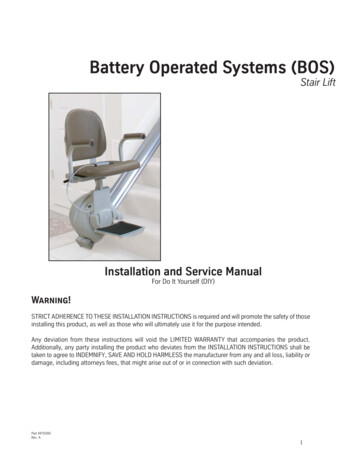
Escort Stair LiftInstallation ManualRead and understand this manual thoroughly before attempting to install or operate the lift. If you have any questions,please contact your Authorized AmeriGlide Dealer or AmeriGlide's Technical Service Department at 866-294-4460.P 866-294-4460 www.ameriglide.com
Table of ContentsINSTALLATION & APPLICATION NOTES3PREPARATION4-11Tool Checklist. . . . . . . . . . . . . . . . . . . . . . . . . . . . 4What's In the Box . . . . . . . . . . . . . . . . . . . . . . . . 5Getting to Know the Rail . . . . . . . . . . . . . . . . . 6Preparing the Rail. . . . . . . . . . . . . . . . . . . . . 7-11INSTALLATION12-21Installing the Rail . . . . . . . . . . . . . . . . . . . . . . . 12Installing the Chassis. . . . . . . . . . . . . . . . . 13-15Installing the Chair. . . . . . . . . . . . . . . . . . . 16-17Re-installing the Charging Strips . . . . . . . . 18Installing the Upper Limit Cam . . . . . . . . . . 19Installing the End Cap/Bracket Cap Option20Charging System . . . . . . . . . . . . . . . . . . . . . . . 21READ AND UNDERSTANDTHIS MANUAL PRIOR TOINSTALLATION OR OPERATION.Please read, follow, and fully understand theinstallation section of this manual before beginning.Knowing the lift's adjustments and becomingfamiliar with tips for proper installation will not onlysave you time and energy, but also help you avoidpossible injury. If you do not understand any portionof installation or operation, please consult ourtechnical service department at 866-294-4460.SYMBOLS USED IN THIS MANUALREAD MANUAL - Pay close attention tothe instructions in the manual.CAUTION - Hazardous situation. If notavoided, could result in serious damageto property.Completion Checklist . . . . . . . . . . . . . . . . . . . 22VERIFYING OPERATIONREQUIRED MAINTENANCE2324-25AUDIO ALERT26REMOTE CONTROL PROGRAMMING27MANUAL LOWERING TOOL28APPENDIX I29Measuring the Rail . . . . . . . . . . . . . . . . . . . . . . 30Flight Angle Charts . . . . . . . . . . . . . . . . . . . . . . 31Cutting the Rail . . . . . . . . . . . . . . . . . . . . . . 32-34APPENDIX II35-38Cutting the Gear Rack . . . . . . . . . . . . . . . . . . . 36Adjusting the Gear Rack. . . . . . . . . . . . . . 37-38SERVICE NOTES2Escort Stair Lift Installation Manual39WARNING - Hazardous situation. If notavoided, could result in serious injury toinstaller or user.SHOCK HAZARD - Disconnect frompower source to avoid personal injury.HEAVY - Be sure to have help available toavoid back injury.TIP - Helpful tips that will facilitate easeof installation.CHECK - Reminder to check certainportions of installation before continuing.INDICATIONS OF USE STATEMENTThe Escort Stair Lift assists with the transfer ofpatients or mobility impaired persons, up and downbetween levels of a residential or private facility.AmeriGlide www.ameriglide.com 866-294-4460
Application NotesINSTALLATION AND APPLICATION NOTESINCLINEThe maximum inclination (angle) the Escort lift can be installed is 45 degrees.The minimum inclination (angle) the Escort lift can be installed is 25 degrees.MAXIMUM RAIL LENGTH32 FeetLOAD CAPACITYThe maximum load capacity is 300 lbs.The lift is not to be used to transport cargo.ELECTRICAL POWER SUPPLY REQUIREMENTSA dedicated 120 VAC 15A 60Hz, 3-wire grounded outlet. NEC requirement.Electrical equipment shall be certified to the requirements of CAN/CSA B44.1/ASME A17.5.ASME 18.1 REQUIREMENTS INSTALLATION REGULATIONSThe Escort lift is an incline stairway chair lift for private residence use only.Installation of this lift must comply to the following American Society of Mechanical Engineers ASME 18.1 – 2011"safety standard for platform lifts and stairway chair lifts". 7.1.1 The structure on which the equipment is installed shall be capable of safely supporting the loadsimposed. 7.1.2 The installation of all electrical equipment and wiring shall conform to the requirements ANSI/NFPA70. 7.6.4 At no point in its travel shall the edge of the footrest facing the upper landing be more than 24 in.above the step or landing as measured vertically.TEC0016 20160714 P/N: 630-00039 Rev CEscort Stair Lift Installation Manual3
PreparationTOOL CHECKLISTPREPARATIONTOOL CHECKLIST 1/2 inch Combination Wrench 3/8" Ratchet with 1/4, 3/8, 1/2, 9/16 inchand 7mm hex sockets 3/8" Drive torque Wrench 6 inch long Ratchet extension Stub Screwdriver - #2 size phillips tip Slotted Screwdriver - #1 or 2 size Set of Hex Wrenches Measuring tape or ruler Level 3/8” power drill Metal cutting saw (hacksaw) Square Safety Glasses Volt meter Hammer Utility knife4Escort Stair Lift Installation ManualAmeriGlide www.ameriglide.com 866-294-4460
PreparationWHAT'S IN THE BOXWHAT’S IN THE BOXBox 11. Stair Lift Chassis (1)2. Remote Controls with Batteries (2)23. Installation Manual (1)4. Owner's Manual / Warranty (1)315. Rail Mounting Brackets (2 per rail)6. Lag Bolts (6 per rail)47. Power Supply (1)8. Power Cord (1)9. Limit Cams (2)6510. Limit Cam bolts and square nuts (4)11. 7 mm Manual Lowering Device (1)12. Timing Gear Rack (1)813. 9/64" Hex Wrench (1)714. End Stop (1)15. Tube of Calcium Base Lubricant (1)16. End Covers (2)17. End Cover Screws (4)9101118. Flat Washers (2)19. Thrust Roller Bearing (1)20. Copper Based Antisieze Lubricant (1)Box 21213151421. Seat Assembly (1) (Escort shown)Box 3 (not shown)22. 2 Aluminum Rails - Installations over 16feet will be shipped with 3 or 4 rails, depending oninstallation requirements23. 2 Splice Bars - Installations over 16 feet willbe shipped with 4 or 6 splice bars, depending oninstallation requirements (Installed on rails)17181619924. 2 sets charging strips (Installed in rails)25. Gear Rack (Installed in rail)2120TEC0016 20160714 P/N: 630-00039 Rev CEscort Stair Lift Installation Manual5
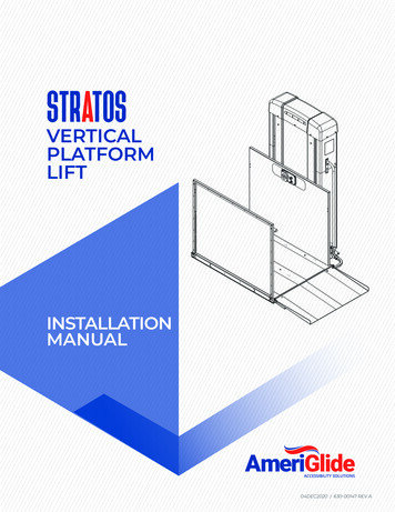
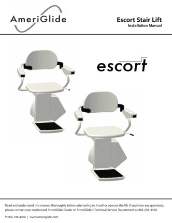
PreparationPREPARING THE RAILGETTING TO KNOW THE RAIL1. Gear Rack Fastener Channel2. Pinion Gear Channels4. Limit Cam Fastener ChannelThe gear rack is fastened using a9/64" hex wrench to tighten theset screws to the plate. The plateslides into the channel. The gearrack will sit inside channel 2" inorder to allow for contact with thepinion gear.These channels allow for the gearrack and pinion gear to interact.The limit cams are attached tothe rail by screwing the supplied10-24 screws and square nuts.The square nut will slide into thischannel and tightened.3. Guide Wheel ChannelThe lower portion is where theGuide wheels will ride in thischannel.412358768591010115. Chassis Wheel ChannelsThe chassis wheels will rideup and down the rail in thesechannels.6. Positive Charging StripChannelPositive charging strip will restinside these channels.1117. Negative Charging StripChannel10. Splice Bar ChannelsNegative charging strip will restinside these channels.Slide splice bars into thesechannels when connecting two ormore sections of rail.8. End Cap Screw Channels11. Rail Bracket ChannelsUse these to fasten the end capsonto the rail.Rail brackets attach to the railusing these channels.9. Main Interior Wire ChannelUsed for running wiring up anddown the rail.6Escort Stair Lift Installation ManualAmeriGlide www.ameriglide.com 866-294-4460
PREPARING THE RAILPreparationPREPARING THE RAILThe following sections are instructions for installing the rail and adjusting the gear rack for lifts that havebeen shipped with pre-cut rails and gear rack. If your rail and gear rack require customization, you MUSTread and follow the instructions in Appendix I and II before continuing.IMPORTANT!Each section of rail must be mounted with two mounting brackets.A mounting bracket must be placed on the next step directly above and below the rail splice joint.The teeth of the gear rack must face toward the wall nearest to where the lift will be installed.The rail should be installed 5 in. away from walls or obstructions.NOTE: These steps are for connecting two rails. If you have more than two rails, follow steps 1-4 for each railbefore moving onto step 5.The top piece of rail has the gear rack protruding out of the lower end. The gear rack is protected by a three (3)inch piece of rail. This rail can be removed and discarded.TIPIt is easiest to prepare the rail in anopen environment such as a room oroutdoors unless maneuverability ofthe full rail will be cumbersome.TEC0016 20160714 P/N: 630-00039 Rev CEscort Stair Lift Installation Manual7
PreparationPREPARING THE RAILINSTALLING THE LOWER LIMIT CAM1. Assemble the limit cams by placing the suppliedscrews into the open side of the cam and looselyscrewing the square nuts onto the screws.[Figure 8-1]NOTE: Both cams may be prepared at this time.Save one for later.Figure 8-12. Slide the lower limit cam square nuts into the limitcam fastener channel and onto rail.[Figure 8-2]3. Position the end of the cam at 1-3/4” within theend of the rail [Figure 8-3]. Secure the limit cams with(2) 10-24 screws and square nuts (provided).Figure 8-2The position of the limit cam can beadjusted later if needed.TIPFigure 8-3LIMIT CAM CHANNEL8Escort Stair Lift Installation ManualAmeriGlide www.ameriglide.com 866-294-4460
PREPARING THE RAILPreparationINSTALLING THE END CAP1. Move the end stop to the end of the gear rack andtighten with a 9/64" hex wrench.2. Install the rail end cap onto the top end of the rail.The wire with the connector should be routed out ofthe end cap on the wall side if charging from the top.Otherwise, excess wire can be tucked into the inside ofthe rail. [Figure 9-1]Figure 9-1CAUTIONAlign end cap screw holes precisely.Do not overtighten.END CAP SCREW CHANNELSTEC0016 20160714 P/N: 630-00039 Rev CEscort Stair Lift Installation Manual9
PreparationPREPARING THE RAILCONNECTING THE RAILS1. Each section of rail is shipped with the gear rackand the charging strips installed with a short pieceof rail covering the protruding rail for protection.With the rail turned upside down, loosen the four(4) allen screws attaching the two sections of railwith the splice bars on the bottom of the protectivesection of rail. [Figure 10-1]2. Pull the protective section apart from the rail. Thiscan be cast away. [Figure 10-1]Figure 10-1NOTE: The rails are labeled top and bottom andwhich side goes toward the wall.3. Position the two ends of the rails close together.Connect the plugs on each end of the two powersupply wires inside the rail pieces.[Figure 10-2 and 10-3]Figure 10-24. Tuck the wire back into the rail channel.5. Slide the rail onto the splice bars and tighten allsplice bar screws. [Figure 10-4]6. Tighten the one loose gear rack screw with theprovided 9/64" hex wrench.Figure 10-3Be careful not to pinch wires whensliding rails together.CAUTIONMAIN INTERIORWIRE CHANNELSSPLICE BARCHANNELSCFigure 10-410Escort Stair Lift Installation ManualAmeriGlide www.ameriglide.com 866-294-4460
PREPARING THE RAILPreparationINSTALLING THE BRACKETS1. Carefully remove the charging strips from the topend of the rail. [Figure 11-1]CAUTIONDo not attempt to remove theattached center wire from the rail asit is attached at the other end to thebottom rail. Pull the wire out only farenough to remove the charging strips2. Slide rail mounting brackets onto rail to theapproximate locations shown [Figure 11-2 and 11-3].Exact positions of brackets will be determined later.Figure 11-1NOTE: The nut side of bracket goes toward the wall.Figure 11-2BOTTOM SECTIONSPLICE JOINT17”4”RAIL BRACKETS[Figure 11-3]TIP12”TOP SECTION9”MAIN INTERIOR WIRE CHANNELThe brackets will fit tightly on the rail.Loosening the bracket bolts will helpthem slide easier. A short piece of2 x 4 may also be used to gently tapthe brackets into place.RAIL BRACKET CHANNELSSTEC0016 20160714 P/N: 630-00039 Rev CEscort Stair Lift Installation Manual11
Figure 12-3InstallationINSTALLING THE RAILINSTALLING THE RAIL1. Set the lower section of rail onto the steps. Thebottom of the rail should be resting on the stairnosings and the bottom end should be 1/4" off ofthe floor at the bottom landing [Figure 12-1].1/4 inchFigure 12-1For The EscortFor The Escort PlusPosition the rail 5" [Figure 12-2]from the wall or any protruding object.Position the rail 6" [Figure 12-3]from the wall or any protruding object.5" From The Wall6" From The WallFigure 12-22. Secure the rail by positioning one lag boltin the lower rail bracket and tightening to step.[Figure 12-4]. The side of the bracket with two holesshould be towards the wall.Figure 12-32. Secure the rail by positioning one lag boltin the lower rail bracket and tightening to step.[Figure 12-4]. The side of the bracket with two holesshould be towards the wall.If a pilot hole is required use a 7/32”diameter drill bit.TIPq ALL RAIL MOUNTING SCREWS ARE SECUREFigure 12-412q ALL SPLICE BAR SCREWS ARE SECUREFor The EscortFor The Escort Plus3. Verify each segment of rail is 5" from the wall or anyprotruding obstruction and secure the remaining railbrackets to the staircase steps with the remaining lagbolts (three (3) per bracket).3. Verify each segment of rail is 6" from the wall or anyprotruding obstruction and secure the remaining railbrackets to the staircase steps with the remaining lagbolts (three (3) per bracket).Escort Stair Lift Installation ManualAmeriGlide www.ameriglide.com 866-294-4460
INSTALLING THE CHASSISInstallationINSTALLING THE CHASSISCHASSISCHASASSS GUIDE WHEEL CHANNELSE LSLHEAVYThe chassis is quite heavy and canbe difficult to install on the rail byone person.PINION CHANNEL1. The chassis slides onto the top of the rail. Carefullypick up the chassis and align the pinion and guidewheels with the rail channels. Insert the chassis ontothe rail. [Figure 13-1 and 13-2] Let it slide down until itstops (the pinion gear will make contact with the gearrack, allowing it to stop). [Figure 13-3]Figure 13-1CAUTIONBe sure the charging strips areNOT in the rail and ensure that thecharging strip wires extruding fromthe top of the rail are not pinchedwhen installing the chassis.NOTE - The chassis may not slide into the rail farenough to allow for the wheels to be fully inside therail. If this is the case, follow the instructions in thissection to lower the chassis further.Figure 13-21. Using a flat head screwdriver, pry out the whiteplastic plug located on the left side of the chassiswhere it is marked for Manual Operation. This willallow for access to the end of the motor shaft.2. Using the provided tool or a 7mm socket attachedto your drill and extension, turn the end of themotor shaft until the wheels are within the rail.Figure 13-3TEC0016 20160714 P/N: 630-00039 Rev CEscort Stair Lift Installation Manual13
InstallationINSTALLING THE CHASSISINSTALLING THE CHASSIS (CON"T)2. On the front side of the chassis, loosen the three(3) bolts on the seat support using a 9/16" socket.[Figure 14-1]Figure 14-1Figure 14-2The top bolt goes through the chassis and has anut on the back which may need to be held forloosening. [Figure 14-2]3. Rotate the seat support until the top plate is leveland tighten the bolts with ratchet. [Figure 14-2]4. With a torque wrench and 9/16" socket tighteneach bolt to between 35 and 50 ft-lb of torque.q SUPPORT MOUNTING SCREWS ARE SECURE14Escort Stair Lift Installation ManualAmeriGlide www.ameriglide.com 866-294-4460
INSTALLING THE CHAIRWARNINGInstallationThree star washers must be locatedbetween chassis and seat supportand bolts must be torqued asspecified to prevent serious bodilyinjury. [Figure 15-1]Star Washerss[Figure 15-1]TEC0016 20160714 P/N: 630-00039 Rev CEscort Stair Lift Installation Manual15
InstallationINSTALLING THE CHAIRINSTALLING THE CHAIRLATCH SPRING LOOPWARNINGLATCH SCREWEscort stair lifts are configuredas a left or right handed unitand cannot be changed. ContactAmeriglide's technical servicedepartment at 866-294-4460 tochange configuration1. Verify the latch spring loop is wrapped aroundthe latch screw. [Figure 16-1]Figure 16-12. Add bearing and lubricant to the seat post:Apply a small amount of Copper Anti-Seize lube(provided) to the thrust roller bearings and sandwichthe bearing between the washers. The lube will helpto keep the parts together and aligned. Apply amoderate amount of lube to the top and sides of thepost. Center the bearing assembly on the top of thepost again using the lube to hold the parts in place.[Figure 16-2a, 16-2b, 16-2c, 16-2d]Figure 16-2bFigure 16-2aFigure 16-2cFigure 16-2d16Escort Stair Lift Installation ManualAmeriGlide www.ameriglide.com 866-294-4460
INSTALLING THE CHAIRInstallationINSTALLING THE CHAIR (CON"T)Figure 17-2Figure 17-13. Route the 3 pin wire connector through the holein the top of the seat chassis and down the left side.[Figure 17-1 and Figure 17-2]4. Reinstall seat assembly: While holding the swivelhandle in the down position, set the seat onto theseat post on top of the seat support. Ensure thebearings are present atop the seat post.Figure 17-35. Plug the 3-pin wire connector from the seat intothe mating connector from the chassis. [Figure 17-3]6. On the backside of the chassis, there is an on/offswitch. Cut off and discard the shipping tie on theswitch. [Figure 17-4]Figure 17-47. Turn the switch to the on position. The unit shouldbeep once when it has completed booting.8. Use the armrest control switch to run the lift downthe rail approximately 30”. [Figure 17-5]NOTE: Refer to page 26 if the unit does not beep.Figure 17-5 LATCH SCREW ENGAGES LATCH SLOTS WHEN SEAT IS ROTATED UNIT DOES NOT OPERATE WHEN SEAT IS ROTATED LATCH SPRING APPLYS PRESSURE TO LATCH SCREWTEC0016 20160714 P/N: 630-00039 Rev CEscort Stair Lift Installation Manual17
InstallationRE-INSTALLING THE CHARGING STRIPSRE-INSTALLING THE CHARGING STRIPS1. Carefully re-insert the charging strips back into therail. [Figure 18-1]2. Slide the charging strips all the way into the rail.Tucking extra charging wire into the Main InteriorWire Channel as you go. Be sure the wire is all theway in leaving only the end piece with the 2-pinconnector outside the rail. [Figure 18-2]Figure 18-1Figure 18-2CHARGING STRIP CHANNELS18Escort Stair Lift Installation ManualAmeriGlide www.ameriglide.com 866-294-4460
UPPER LIMIT CAMInstallationINSTALLING THE UPPER LIMIT CAM1. Gather the limit cam you assembled from page 8.2. Insert the upper limit cam into the end of the rail.[Figure 19-1 and 19-2]3. Position the end of the cam at 1-3/4” from the topof the rail. Secure the limit cams with (2) 10-24 screwsand square nuts (provided). [Figure 19-3]Figure 19-1CAUTIONAlign end cap screw holes precisely.Do not overtighten.IMPORTANT!LUBRICATE THE GEAR RACK.A tube of lubricant is provided in the chassis box.Lightly lubricate the entire gear rack by squeezingthe tube onto the gear rack.Figure 19-2LIMIT CAM CHANNELFigure 19-3TEC0016 20160714 P/N: 630-00039 Rev CEscort Stair Lift Installation Manual19
InstallationINSTALLING THE END CAPSINSTALLING THE END CAP1. Install the rail end cap onto the top end of the rail.The wire with the connector should be routed out ofthe end cap on the wall side if charging from the top.Otherwise, excess wire can be tucked into the insideof the rail. [Figure 20-1]Figure 19-1END CAP SCREW CHANNELSINSTALLING THE BRACKET CAPS (OPTION)1. The bracket covers will cover the outside of thebottom piece of the brackets in order to hide the lagbolt and swivel assembly.2. Place the bracket cover over the outside of thebottom piece of the bracket and slide it down until itsnaps into place.3. Repeat on all brackets.20Escort Stair Lift Installation ManualAmeriGlide www.ameriglide.com 866-294-4460
CHARGING SYSTEMInstallationCHARGING THE BATTERIES1. The power supply has a cord with a 2-pinconnector that mates to a cable from the chargingstrips. Connect the power supply at either the top orbottom end of the rail.2. Plug the power supply into a dedicated120VAC 15A outlet.NOTE: The power supply should be connected to anoutlet at all times and the switch on the back of thechassis must remain on for the batteries to charge.TEC0016 20160714 P/N: 630-00039 Rev CFigure 20-1Escort Stair Lift Installation Manual21
InstallationCHECKLISTCOMPLETION CHECKLISTComplete Checklist before riding the lift. Three star washer are located between the chassis and the seat support. Chair mounting bolts are secure and torqued to specified value. The chair locks in all positions when rotated. Lift does not operate when chair is rotated from the normal ride position. Rail mounting bracket and mounting feet bolts and nuts are secure. The spacing of the gear rack at each end of the rail is correct. The footrest safety pan stops lift when obstructed in each direction. The lift stops when it comes in contact with the limit cams. All electrical wires are clear of moving parts.22Escort Stair Lift Installation ManualAmeriGlide www.ameriglide.com 866-294-4460
Verifying Lift OperationVERIFYING LIFT OPERATIONObserve the following rules when operating the lift. Never stand on the footrest when the lift is moving. Never exceed the weight capacity of the lift. Never use the lift to transport cargo. Always place your feet in the center of the footrest. Always lock the seat in the ride position when using the lift. Always use the seat belt and remain seated in the center of the seat.DIRECTION CONTROLSThe Escort Stair Lift is equipped with an armrest mounted control and two wireless remote controls. Allcontrols are constant pressure.To prevent accidental movement, the lift has a programmed delay before moving.When using the remote control, aim the remote toward the lift’s receiver eye located on side of the lift.FOOTREST SAFETY PANThe lift is equipped with a safety pan mounted on the bottom of the footrest. Should the safety panencounter an obstruction, the lift will stop abruptly. The lift can be backed away from the obstruction.CHAIR LOCKThe lift will not operate if the chair is not locked in the ride position.When using the lift at the top of the staircase, always verify that the seat is securely locked in the load(rotated) position before attempting to sit in the chair.SEAT BELT RESTRAINTAlways use the seat belt.TEC0016 20160714 P/N: 630-00039 Rev CEscort Stair Lift Installation Manual23
MaintenanceREQUIRED MAINTENANCEThe rail gear should be cleaned once a year or more frequently if exposed to contaminants such as pet hair,excessive dust, etc. Wipe debris from the gear teeth. Apply a small amount of lubricant onto a clean clothand wipe across the gear teeth. Do not apply too much lubricant. Over lubrication will attract dirt and debris.Ensure all rail, footrest and seat support fasteners are tight.The seat post and thrust roller bearings should be lubricated once a year or sooner if used frequently.TIPTIPTIPSHOCKHAZARD24Gear rack should be lubricated with a multi-purpose calcium grease.DO NOT USE any type of light weight penetrating oil (WD-40, GUNK, Kroil,Liquid Wrench etc.)The seat post and thrust roller bearing should be lubricated with a copper basedantisieze lubricant. DO NOT use any type of light weight penetrating oil (WD-40,GUNK, Kroil, Liquid Wrench etc.)The lift and aluminum rail can be cleaned with any commercial window cleaner.DO NOT USE abrasive cleaners.To prevent electrical shock or damage to the lift, disconnect the 120 VAC power whencleaning the lift. Never apply cleaning liquids directly on the rail mounted charging stationsor electrical safety switches.Escort Stair Lift Installation ManualAmeriGlide www.ameriglide.com 866-294-4460
MaintenanceSEAT REMOVAL FOR LUBRICATION1. Lower stair lift to bottom of staircase.2. Turn lift off at switch on backside of chassis.3. Remove the seat:a. Rotate the seat 90 degrees. [Figure 25-1][Figure 25-1]b. Unplug three pin wire connector from the seatout of the mating connector from the chassis.[Figure 25-2]c. Return seat to normal position.[Figure 25-2]d. While depressing swivel lever, lift seat verticallyoff the seat post. Rotating the seat back and forthwhile lifting may be helpful in removal of the seat.[Figure 25-3]4. Refer back to the INSTALLING THE CHAIR section(page 16) for applying the lubrication andreinstalling the seat.[Figure 25-3]TEC0016 20160714 P/N: 630-00039 Rev CEscort Stair Lift Installation Manual25
PCB Control BoardCAUTIONAUDIO ALERTSNever touch the circuit board chipsor circuits. Static electricity willdamage the circuit board. Whenhandling the circuit board alwaysdisconnect the 120 VAC power anduse a static discharge wrist band.AUDIO ALERTSIf your lift does not operate, diagnose theproblem by listening to the beeps emitted: No beeps means either the lift is not turned onor the battery has no charge. A long beep when the control switch ispressed indicates the lift is touching anobstruction. One beep per second for 30 seconds (aftera 30 second delay) indicates the lift hasbeen stopped off the charging station. It isrecommended that the lift be immediatelymoved to a charging station (located eitherend of the rail). Two beeps every 60 seconds indicates a majorfault with the circuit board. Turn unit off andback on to reset. Three beeps every 60 seconds indicate a majorfault with the footrest sensor. Turn unit off andback on to reset. Seven beeps every 60 Seconds indicate amajor fault with the slow down switches. Turnunit off and back on to reset. Eight beeps every 60 seconds indicate a majorfault with the limit switch. Turn unit off andback on to reset.If your lift fails to reset, contact your dealer forservice.NOTE: A fault is defined as major any time it requiresthe unit to be turned off and back on to reset.26Escort Stair Lift Installation ManualAmeriGlide www.ameriglide.com 866-294-4460
Remote ControlREMOTE CONTROLPROGRAMMINGIf there are multiple lifts in the home, the infra-redremote controls can be programmed to work withindividual lifts.1. Remove the battery door on each IR remote.2. Move the dip switches to a different code. The tworemotes must be set to the same code.3. Replace the battery doors.4. Use the seat control switch to move the lift so thatit is not on a limit switch.5. Turn the ON/OFF switch to OFF.6. Swivel the seat toward the upper landing.7. Press and hold the footrest safety pan tosimulate an obstruction.8. Turn the ON/OFF switch to ON. Fast beepingshould occur indicating the circuit board is in the IRlearning mode.9. Release the footrest safety pan and swivel the seatback to the normal, riding position.10. Aim the first IR remote at the chassis, press andrelease the UP or DOWN button. The fast beepingshould end with a single beep, indicating that thefirst remote is programmed.11. Aim the second IR remote at the chassis, press andrelease the UP or Down button. Two beeps shouldsound indicating the second remote is programmed.TEC0016 20160714 P/N: 630-00039 Rev CEscort Stair Lift Installation Manual27
Manual Lowering ToolMANUAL LOWERING TOOLCAUTIONIf the lift is inoperable because it has driven onto the final limit switch or has run out ofpower, it has to be manually moved off the final limit1. Turn the lift off at the power switch.NOTE: Disconnecting the power supply does notturn the lift off. The power supply only charges thebatteries.2. Remove the round plastic plug on the end of thechassis to access the end of the motor shaft.[Figure 28-1]3. Place the manual lowering tool onto the end ofthe motor shaft and rotate until the final limit switchbecomes disengaged.Figure 28-14. Re-install the plastic plug and turn the lift "ON".28Escort Stair Lift Installation ManualAmeriGlide www.ameriglide.com 866-294-4460
CUTTING THE RAILAppendix IAPPENDIX IMeasuring andCutting the RailThe following section is for installationswhere the rail has not been ordered pre-cut.TEC0016 20160714 P/N: 630-00039 Rev CEscort Stair Lift Installation Manual29
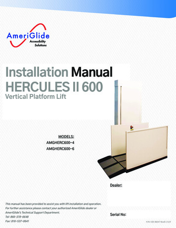
Appendix IMEASURING THE RAILMEASURING THE RAIL1. Measure from the nose of the top step to the pointon the landing where the rail will rest [Figure 30-1].Enter this measurement into BOX 1 of the Rail LengthWorksheet below.2. To figure the overall length of the rail you mustknow the flight angle of your stairway. Measure yourrise and run as shown in Figure 30-2. Use the chart onpage 31 and its key to figure the flight angle and thecorresponding overrun. Enter the overrun into BOX 2of the Rail Length Worksheet belowFigure 30-1RISERISERISERUNRUNRUNFigure 30-23. Add BOX 1 and BOX 2. Enter the value into BOX 3.This is the overall length of the rail.NOTE: Seat Height Compensation The Rail length shown in BOX 3 of the RailLength Worksheet will position the footrestlevel with the upper floor. The seat height will be 18 inches. To raise theseat height, additional rail length must beadded. The length shown in the Overrun to RaiseSeat column of the Rise and Run Chart Key isthe length of rail that must be added for eachadditional inch of seat height. The maximum allowable overrun is 12 inches.Rail Length WorksheetBOX 1BOX 2BOX 330Escort Stair Lift Installation ManualAmeriGlide www.ameriglide.com 866-294-4460
MEASURING THE RAILFLIGHT ANGLE CHART6”32.39.75” 31.610” 31.010.25” 30.310.5” 29.710.75” 29.211” 28.611.25” 28.111.5” 27.611.75” 27.112” 26.612.25” 26.112.5” 25.612.75” 25.213” 24.8Average Run9.5”Appendix IAverage ht Angle (degrees
6 Escort Stair Lift Installation Manual AmeriGlide www.ameriglide.com 866-294-4460 Preparation PREPARING THE RAIL GETTING TO KNOW THE RAIL 3 1 2 8 4 5 9 7 5 11 10 10 6 1 1. Gear Rack Fastener Channel The gear rack is fastened using a 9/64" hex wrench to tighten the set screws to the plate. The plate