Transcription
DriveWare User's GuideDriveWindow Light 2
DriveWindow Light 2User's GuideDriveWare Code: 3AFE 64560913EFFECTIVE: 15.10.2013SUPERCEDES: 22.11.2010 2013 ABB Oy. All rights reserved.
Table of ContentsTable of Contents . iiiChapter 1 – Introduction to this Guide . 1-1Overview . 1-1What this Guide Contains . 1-1Conventions used in this Manual . 1-1Parameter . 1-1Drive dependent parameter . 1-1Signal . 1-1Parameter signal . 1-1Upload . 1-2Download . 1-2Online . 1-2Offline . 1-2Offline configuration . 1-2Backup . 1-2Restore . 1-2Wizard. 1-2ACS 100-400 and DCS400 drives . 1-2ACS800 series . 1-2Parameter Data . 1-2Chapter 2 – Overview . 2-1Overview . 2-1Chapter 3 – Getting Started . 3-2System Requirements . 3-2Installing DriveWindow Light . 3-2NT4 . 3-2Win2000 and WinXP . 3-2Starting DriveWindow Light . 3-2Connecting Drive and PC . 3-2Chapter 4 – Drive Status . 4-2Status Panel. 4-2Drive Status . 4-2Advanced Status . 4-3Status Bar . 4-3Function Buttons . 4-3Online/Offline . 4-4Chapter 5 – Parameters . 5-2Parameter Browser . 5-2Online Mode . 5-2Offline Mode . 5-3Parameter Group . 5-4Parameters & Signals . 5-4Backup/Restore . 5-5Offline configuration . 5-7Parameter Subset Selection . 5-8DriveWindow Light 2iii
Table of ContentsCompare Parameters . 5-9Search Parameters .5-10I/O Mapping Table .5-10Start-up Wizard .5-11External Applications .5-11Adaptive Programming .5-11Sequence Programming .5-13Main Window .5-13State Property Windows .5-14Chapter 6 – Drive Control Panel . 6-2Operation . 6-2Step Function . 6-3Chapter 7 – Drive Monitoring . 7-2Operation . 7-2Monitoring Settings . 7-3File Operations. 7-5Chapter 8 – Settings . 8-2Communication Settings . 8-2Confirmation and Options . 8-4Chapter 9 – Error Messages . 9-2Parameter Browser . 9-2Backup/Restore . 9-3Drive Status . 9-4Drive Identification . 9-4Communication . 9-6Monitor . 9-7Wizard . 9-7ivDriveWindowLight 2
Chapter 1 – Introduction to this GuideOverviewThe document describes how to use the DriveWindow Light 2application.What this GuideContainsChapter 2 – OverviewChapter 3 – Getting Started describes how to install and startDriveWindow Light.Chapter 4 – Drive Status describes how to monitor the status of thedrive.Chapter 5 – Parameters describes how to operate with theparameters in online and in offline mode.Chapter 6 – Drive Control Panel describes how to control theconnected drive.Chapter 7 – Drive Monitoring describes how to monitor driveoperations.Chapter 8 – Settings describes how to view and edit the settings ofDriveWindow Light.Chapter 9 – Error Messages of DriveWindow Light are listed in thischapter. Possible reasons and solutions for these messages are alsolisted.Conventions usedin this ManualParameterParameters are frequency converter variables, which are brought upto users for adjusting drive operations. They are identified with fourdigits (e.g. 12.34). In this document the term parameter is used torefer not only to parameters but also drive dependent parameters,signals and parameter signals.Drive dependentparameterDrive dependent parameters are such that a default value cannot bedefined in the parameter files. They are dependent on the particulardrive rating values.SignalParameter signalDriveWindow Light 2Signals are read only parameters, which are cyclically updated inonline mode.Parameter signals are writeable parameters, which are updated likesignals.1-1
Introduction to this GuideUploadDownloadUpload loads parameter values from the drive to Parameter Browser.Download writes parameter values from Parameter Browser to thedrive.OnlineIn online mode drive status and signals are uploaded cyclically fromthe drive to the PC and changed parameter values are written to thedrive immediately.OfflineIn offline mode there is no communication between the PC and thedrive without specific commands from the user.OfflineconfigurationWith offline configuration it is possible to change parameter valueswithout a connected drive.BackupWith backup operation parameters are uploaded from the drivestraight to a PC file.RestoreWith restore operation parameters are written from a PC file straightto the drive.Note! Drive type and software version number together with theparameter file are checked when restoring.WizardACS 100-400 andDCS400 drives1-2Wizards are DLL-files, which are using DriveWindow Light’scommunication module interface to talk with the drive.In this document the term ACS 100-400 and DCS400 drives is usedwhen the features of DriveWindow Light are different depending onthe type of the connected drive. The term includes the ACS140,ACS160, ACS400 and DCS400 drive series, where all the ACS drivesbelong to the range of the DriveIT Low Voltage AC Drives.ACS800 seriesThe term ACS800 series is used in the same way as ACS 100-400and DCS400 drives. The term includes the ACS800 drive series andif not otherwise mentioned the ACS600 drive series. Standard, pumpand fan control together with spinning control applications aresupported. The drives belong to the range of the DriveIT Low VoltageAC Drives.Parameter DataThe term parameter data refers to all other information about aparameter than its actual value. That is: parameter's name, min andmax values, unit and information concerning the way DWL processesthe actual value.DriveWindow Light 2
Chapter 2 – OverviewOverviewDriveWindow Light is a start-up and maintenance tool for e.g. theACS140, ACS160, ACS310, ACS320, ACB330, ACS350, ACS355,ACS400, ACH400, ACS510, ACB530, ACS550, ACH550, ACS600,ACS800, DCS400, DCS550 and DCS800 drive series.DriveWindow Light is designed to run under the Microsoft WindowsNT 4.0, Windows 2000, Windows XP, Windows Vista and Windows 7operating systems on IBM-compatible PCs.The key functions of DriveWindow Light are the following: DriveWindow Light 2Show the actual status of the connected driveEdit and show the drive parametersSave and load drive parametersBack up and restore drive parametersOffline configuration of drive parametersGraphical monitoring of drive signalsNumerical monitoring of drive signalsRun step response testsControl the drivePlug ’n Play connection of drives2-1
Chapter 3 – Getting StartedSystemRequirementsTo operate DriveWindow Light your computer must meet the followingminimum requirements:Table 1 System RequirementsInstallingDriveWindow LightCategoryMinimum RequirementProcessorPentium 133 MHzOperating SystemWindows NT 4.0 (SP6), Windows 2000,Windows XP, Windows Vista or Windows 7Display1024x768, 256 colorsSystem Memory(RAM)64 MBHard Disk Space80 MBInsert the DriveWindow Light CD-ROM into the CD drive of your PC.NT4 Start Control PanelDouble click on Add/Remove ProgramsClick the Install buttonFollow the instructionsWin2000 andWinXP Start the Control PanelDouble click on Add/Remove ProgramsClick the Add New Programs buttonFollow the instructionsNote! When installing DriveWindow Light you must haveAdministrator privileges.StartingDriveWindow LightDriveWindow Light is started with a shortcut found in the DriveWarefolder.Connecting Driveand PCTo connect the drive and the PC you need different hardwaredepending on the drive type. On PC side you can use any free RS232port.3-2DriveWindow Light 2
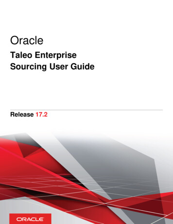
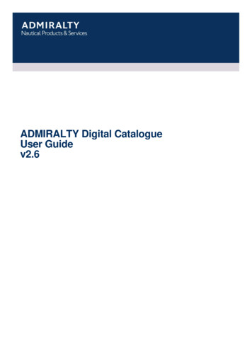
Getting startedIf you have an ACS310, ACS320, ACS350, ACS355, ACS/ACH550or similar drive you need an OPCA-02 adapter.If you are working with a DCS400, DCS550 or DCS800 drive you donot need any other hardware components then a standard serialcable. You can connect the cable directly into the RS232 port of thedrive. With other drives you need a standard serial cable and anappropriate adapter.If you are connecting an ACS140 or an ACS400 drive you must havean RS485/RS232 adapter. The adapter used with these drives isshown in Figure 1. For ACS160 drives a CFB-RS adapter is neededand to connect an ACS600 or ACS800 drive a panel link isestablished via an NPCU-01 adapter.If you do not have the adapter needed you may order one from alocal ABB representative.Figure 1 RS485/RS232 AdapterDriveWindow Light 23-3
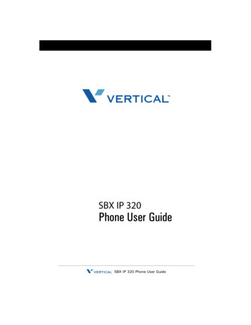
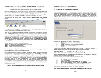
Chapter 4 – Drive StatusStatus PanelDrive StatusDrive Status Panel is located on the left side of the DriveWindowLight main window. The status panel can be hidden or shown with theView - Drive Status Panel menu command.The upper part of the status panel shows information about theoperation of the drive. It contains the following items for all drives: Drive type and its Modbus node numberDrive remote/local mode (Auto / Hand-Off for ACH550)Running/stoppedRunning direction (forward or reverse)Drive state (OK, Warning or Fault)The name of the active fault or alarm. If the fault/alarm text is longer thanthe status panel, you can move the mouse cursor on it and see the textas a tool tip.Note! With ACS350, ACS/ACH550 and DCS800 (and similar) drivesthe modbus node number shown is usually 247, the default whencommunicating through the panel connector. This is different than thenode number used when communicating through standard modbusfieldbus connector.The rest of the information about the drive operation varies betweenAC and DC drives. For AC drives the status panel contains thefollowing items: Output frequency [Hz]Current [A]Power [kW]Speed [rpm]For DC drives the following items are displayed: DriveWindow Light 2Armature voltage [V]Current [A]Power [kW]Speed [rpm]4-2
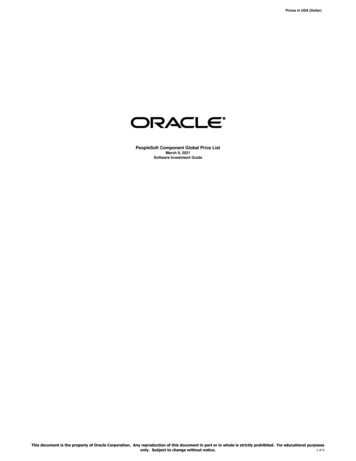
Drive StatusAC drivesDC drivesFigure 2 Drive StatusAdvanced StatusDrive Advanced Status shows the status word and the control word ofthe drive. Advanced status is shown or hidden with the View Advanced Status menu command. Status and control words areshown in both binary and hexadecimal format. With ACS drives bothStatus Word and Control Word are frequently read from the drive.With DCS drives only Status Word is read from the drive and ControlWord is the latest one sent to the drive.Figure 3 Drive Advanced StatusStatus BarStatus Bar, situated at the bottom of the screen, shows drive andconnection status together with additional information on what thedifferent menu commands and buttons affect. Status Bar is shown orhidden with the View – Status Bar menu command.Figure 4 Status BarFunction ButtonsThe lower part of Drive Status Panel contains the following functionbuttons: DriveWindow Light 2Wizard - Opens the Wizard windowMonitor - Opens the Monitor window4-3
Drive StatusFigure 5 Function buttonsOnline/OfflineThe state between online and offline is changed with the online/offlinebuttons in the Application Toolbar or with the Communication –Online and Communication - Offline menu commands. TheApplication Toolbar is shown or hidden with the View – ApplicationToolbar menu command.Table 2 Application Toolbar buttonsButtonsFunctionSwitch to online mode.Switch to offline mode.Upload all parameter values (and parameterdata if it is re
without a connected drive. With backup operation parameters are uploaded from the drive straight to a PC file. With restore operation parameters are written from a PC file straight to the drive. Note! Drive type and software version number tog