Transcription
Installation ManualHERCULES II 600Vertical Platform LiftMODELS:AMGHERC600-4AMGHERC600-6Dealer:This manual has been provided to assist you with lift installation and operation.For further assistance please contact your authorized AmeriGlide dealer orAmeriGlide’s Technical Support Department.Tel: 866-378-6648Fax: 816-537-0641Serial No:P/N: 630-00047 RevB 11519
P/N: 630-00047 RevB 11519TABLE OF CONTENTSpecifications 4Safety & Code Requirements 5Site Requirements 5Preliminary Checks 6Review All Parts 6Tools Needed 6Materials Needed 6Preparing to Install 7Installing the Platform 10Controller Harness Connections 10Installing Outer Guard Panel 10Installing the Ramp 11Top Landing Gate (optional) 12Top Landing EMI Interlock (optional) 13Fascia Panel (optional) 13Anchoring the Lift 14Setting the Limit Switches 16Verifying Lift Operation 17Manual Override 182 // 24Hercules II 600 Vertical Platform Lift Install Manual www.Ameriglide.com 866-378-6648
P/N: 630-00047 RevB 11519GLOSSARYUsing the ManualThis Installation Manual providesstep-by-step instructions on how to installa Hercules Residential Platform Lift. Readand understand the entire Manual beforebeginning to install the lift. Also, ensurethat the end-user has a copy of the Owner’sManual with operating instructions before itis put into service.If you have any questions, contacttechnical service at 1-866-378-6648.Hercules II 600 Vertical Platform Lift Install Manual www.Ameriglide.com 866-378-66483 // 24
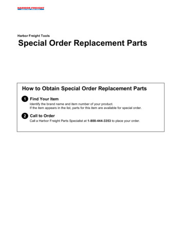
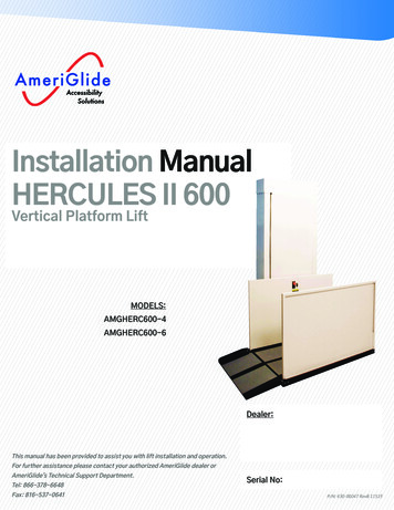
P/N: 630-00047 RevB 11519LIFT SPECIFICATIONSTop CoverData / Serial TagRamp Roller GuidePlatform ControlsPlatform FrontGuard PanelPlatform RearGuard PanelPlatform AssemblySafety Pan AssemblyFolding RampSPECIFICATIONSPayload CapacityHeightFoot PrintPlatform SizeInput VoltageControl VoltagePlatform SpeedMotor4 // 24600lbHercules 400 - 53" Hercules 600 - 77"50" x 64"36" x 48"120VAC - 15A grounded circuit24VAC10' min⅓HP - 90VDCHercules II 600 Vertical Platform Lift Install Manual www.Ameriglide.com 866-378-6648
P/N: 630-00047 RevB 11519SAFETYREAD ALL INSTRUCTIONS IN THIS MANUAL BEFORE INSTALLING / OPERATING THE LIFT. Always wear eye protection while installing or servicing this product. Always disconnect this product from the electrical source before servicing it. Do not wear loose clothing or jewelry when working on this product. Do not disable any safety equipment or switches supplied with this lift. Stay away from all drive train components while the lift is operating. Do not exceed the maximum payload capacity of 600lb. Do not ride on the lift until it is anchored in place. This product is designed only for lifting people and mobility devices. Do not use forany other purpose.This lift is designed to meet ASME A18.1 section 5 and CSA B44.1/ASME A17.5 with theaddition of certain options. Code requirements for vertical platform lifts vary dependingon location. Installers are responsible for contacting their local, state or county codeenforcement office to determine all applicable regulations prior to installing verticalplatform lifts.SITE REQUIREMENTS The lift requires a 120VAC 15AMP grounded circuit. Outdoor installations require a GFI protected circuit. Only install the lift on a 4" thick, level 3,500PSI reinforced concrete slab. Footprint requires 50" x 64" area (this includes the folding access ramp.) Lift must meet NFPA 70 (NEC) National Electrical Code adopted in area of installationINDICATIONS OF USE: THE VERTICAL PLATFORM LIFT SERIES IS USED TO ASSISTTRANSFER OF PATIENTS OR MOBILITY IMPAIRED PERSONS, UP AND DOWN BETWEENLEVELS OF A RESIDENTIAL HOME.Hercules II 600 Vertical Platform Lift Install Manual www.Ameriglide.com 866-378-66485 // 24
P/N: 630-00047 RevB 11519PRELIMINARY CHECKSREVIEW ALL PARTS Check the lift for shipping damage. If you find any damage contact the freightcarrier to file a damage claim. Verify the products match that described on the packing list attached to theexterior packaging.Tools Needed ½" Hammer Drill ⅜" Masonry Drill Bit Appliance Dolly Hammer Level Measuring Tape Socket Wrench Set Screwdriver Set Allen Wrench Set Volt MeterMaterials Needed 4 Floor AnchorsWe recommend securing the lift using our anchor kit. If you purchase your own anchors theymust use ⅜" x 4" bolts and have a minimum tensile strength of 6000lb.NOTE: DO not use “Tapcon” anchor. Use a “Wedge Anchor” or “Sleeve ExpansionAnchor”.6 // 24Hercules II 600 Vertical Platform Lift Install Manual www.Ameriglide.com 866-378-6648
P/N: 630-00047 RevB 11519PREPARING TO INSTALLFINAL6:SITEStepTurnINSPECTIONover joined rails and install the remaining two (2) jointfasteners and firmly tighten with 3/16" Allen wrench. Then slide rackpiecesdownto coverjoint.Verify thesurfaceof thelift will mount to is smooth and level. This surface mustStepbemade7: Installfrom 3,500PSIrail bracketsreinforcedby looseningconcretethewithscrewsa minimumand snappingthickness of 4".Verifybracketeachthat thereedgeis enoughinto the spaceslot, orforslidethe thelift’sbracketsfootprint.on Includefrom thespacetop for theoftherail.folding access ramp, allowing 50" x 64". Size is for 36" x 48" platform. .the platform and the upperWhen inthegapnutswill be onwalllanding must be no less than ⅜" and no greater than ¾".CautionVerify that the running clearance around the lift complies with any codes for your area. Step 8:The horizontal gap between the guard panel and any wall or barriermust be no less than 2" and no greater than 3".TheASMErails,A18.1Code requiresthatbracketa gate inorplacedoor beat theA . Fordoubletightenthe first railso installedthat,landing.whenupperturnedover, the back of the bracket touches the rear of thefirststepfrombottomheadlanding.tightenthe second Verify thatthesufficientroomPlaceexistsandabovethe lift.The lift will requireand 8" of clearance above the platform floor when the lift is at the upperagainlanding.WarningThe area below the top landing edge must be covered by a smooth vertical fascia toeliminate pinch points between the platform and landing. Requirement by ASME A18.1safety standard for platform lifts and stairway chair lifts.so the backof the bracket touches the rear of the step. ThenCONNECTINGELECTRICITYplace the fourth and final bracket on the last step before the topThe lift requires a 120VAC 15AMP grounded, dedicated electrical outlet withinlanding, again tightening it so it touches the front of the rear of6' of the lift. Plug the lift directly into the power outlet. Do not plug anything elsethe last step.into the same outlet as the lift.B. For single rails, tighten the first rail bracket in place so that,NOTE: Follow NFPA70 National Electrical Code (NEC) adopted in your state,when turned over, the back of the bracket touches the rear of thecounty or city jurisdiction.first step from the bottom landing. Place the other rail bracket onWarningDo not ride on the lift until it has been anchored in place.Hercules II 600 Vertical Platform Lift Install Manual www.Ameriglide.com 866-378-66487 // 24
P/N: 630-00047 RevB 11519INSTALLING PLATFORMINSTALLING PLATFORMStep 1: The lift will arrive either on its back on a pallet, or standingon a pallet. Carefully cut away and remove the shrink wrap to exposethe platform, guard panels, ramp, and lift tower.Step 2: Unpack the platform, guard panels, ramp and smaller hardware box from the lifttower. The mounting bolts,nuts an spacers that secure the platform to the lift carriage areincluded in the small hardware pack.Step 3: Carefully tilt the lift tower up and remove from the pallet.Remove the top cover and the front panel from the lift tower byremoving the three Phillips head screws at the top. Set the topcover aside. Grasp the loose panel by its sides and raise it up andslide it to the side, freeing it from the lift frame.Step 4: Plug the platform control box into the Controller Harness that exits the plastic chainon the left tower. Plug lift tower into power source and, using the rocker switch on the platformcontrol box, carefully lower the platform carriage to the ground.NoteIf the red emergency stop button on the front of the control box is pushed in the lift willnot move. Grasp the red button and pull it straight out to disengage the emergency stop.8 // 24Hercules II 600 Vertical Platform Lift Install Manual www.Ameriglide.com 866-378-6648
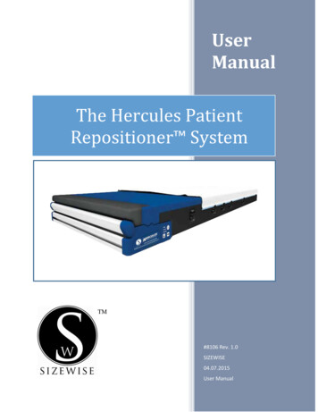
P/N: 630-00047 RevB 11519CONTROLLER HARNESS CONNECTIONSLow VoltageCircuit BreakerUpper & LowerCall / SendsSafety PanJumperUpper LandingInterlockUpper & LowerLimit SwitchHigh VoltageCicurt Break(AC unit only)Platform TravelingCableNote: Lift will be shipped with jumper in place. (Red tags-note jumpers) Safety Pan Top Landing gateHercules II 600 Vertical Platform Lift Install Manual www.Ameriglide.com 866-378-66489 // 24
P/N: 630-00047 RevB 11519INSTALLING PLATFORM / OUTER GUARD PANELStep 5: Align the four platform mountingholes with those on the lift carriage. Insert a½" x 3" bolt into each of the lower holes. Placethe spacers between the carriage flanges andthe platform arm upper holes and insert ½"x 3" bolts. Install the low-profile lock nuts onthe upper bolts and the standard ones on thelower bolts.Step 7: Removethe safety panbypass jumperfrom the front ofthe electronics boxat the top of thelift. Verify that theplatform safety panis operational bypressing up on the pan when the lift is comingdown. The lift should stop but be able to movein the up direction.INSTALLING OUTER GUARD PANELStep 6: Locate the safety pan harnessexiting from the rear of the platform andplug it into the harness at the end of theplastic chain in the lift tower. Secure theplatform control harness and the safetyharness under the clip at the top of thecarriage flange.Step 1: Insert the guardpanel posts in the pocketsin the platform. The smoothside of the guard panel facestoward the center of theplatform.Bolt each post in place with (2) 5/ 16 - 18 X 2" and(1) 1/ 4 - 20 X 2" hex head bolts. If you have a 90 exit platform, install the end guard panel usingthe provided bracket and bolt to inner guardpanel.Step 2: Install the platformcontrol box on the rear guardpanel using screws and nutsthrough the panel.Step 3: Install rear panel on platform byinstalling guard panel posts into the pockets atthe rear of the platform and bolt in place.Step 4: Install platform control box to rearguard panel.Step 5: Install front guard panel by removing(2) 5/ 16 - 18 X 2" and (1) 1/ 4 - 20 X 2" hex headbolts.10 // 24Hercules II 600 Vertical Platform Lift Install Manual www.Ameriglide.com 866-378-6648
P/N: 630-00047 RevB 11519INSTALLING RAMPINSTALLING THE RAMPStep 1: Install the ramp roller guide on the side of the lift tower using the screwsalready installed in the panels.NOTE: The longer flange will point toward the floor.Step 2: Attach the two ramp pivot tabs to the lower landingsides of the platform. Reinsert the hex bolts, one of which willgo through the guard panel post, and tighten.Step 3: Attach the ramp to the pivot tabs using shoulderbolts and locking nuts. Tighten the nuts until they seatagainst the bolt shoulder.Step 4: Attach the ramp roller arm by bolting it to theunderside of the ramp. The ramp roller should align and makecontact with the ramp roller guide. The roller should ride upthe tower arm, folding the ramp when the platform is raised.Hercules II 600 Vertical Platform Lift Install Manual www.Ameriglide.com 866-378-664811 // 24
P/N: 630-00047 RevB 11519TOP LANDING GATETOP LANDING GATE (OPTIONAL)The optional top landing gate is providedwith a combination mechanical lock andelectric contact (interlock).The interlock: Prevents the lift from running if thegate is not closed. Prevents the gate from being openedif the platform is not at the toplanding. Unlocks when the lift is on the upperlimit switch.Remove the latch post cover and connectthe call-send and interlock wire harnesses.The vertical posts of the gate must beattached to a supporting structure, (thegate is not designed to be freestanding).A length of multi‐conductor wire will needto be ran from the bottom of the lift towerup to the landing gate. Consult local codesfor type and mounting requirements. Afterwiring is completed, the wiring harnessmust be plugged into it appropriatereceptacle on the controller (ref pg. 9).Wiring ConnectionsEMI Gate HarnessGate (4) Prong Molex PlugsCall/Send HarnessLift HarnessBlueBlueYellowWhiteRedRed(3) Prong Molex PlugsA crescent shaped key is providedto manually unlock the gate duringinstallation. The key is inserted from theback side to lift up on the solenoid thatholds the gated locked.Mount the gate by placing onto the upperlanding making sure to align the gateopening with the platform (outer guardrail not shown for clearity). There are anumber of attachment holes provided in thethreshold portion of the gate for mountingusing wood lag screws or concrete anchorsas appropriate.12 // 24Hercules II 600 Vertical Platform Lift Install Manual www.Ameriglide.com 866-378-6648
P/N: 630-00047 RevB 11519FASCIA PANELFASCIA PANEL (OPTIONAL)A fascia panel provides a smooth surface for the platform edge to run against to prevent anyshear or obstruction hazards and must be utilized.A running clearance of no more than 3/4" and no less than 3/8" must be maintained between theedge of the platform and the fascia panel.NoteThe ASME A18.1 Code requires smooth, vertical surface below the upper gate or door toprevent a pinch point. Reference ASME A18.1 (Rule 5.1.1.2)HerculesHerculesII 600 VerticalII 750 VerticalPlatformPlatformLift InstallLift Manual www.Ameriglide.com 866-378-664813 // 24
P/N: 630-00047 RevB 11519TOP LANDING EMI INTERLOCKSTOP LANDING EMI INTERLOCKS (OPTIONAL)The optional EMI Interlock is provided with a combinationmechanical lock and electric contact. They are to be used withexisting doors.The interlock: Prevents the lift from running if the gate is not closed. Prevents the door from being opened if the platform is not atthe landing. Unlocks when the lift is on the landing limit switch.EMI Interlock1. Position interlock to door jamb and mark mounting holes.2. Fasten Interlock to door jamb with #8 wood screws.3. Route 4-conductor Interlock cable thru hole in top of interlock and make wire connections.4. Attach door keeper and emergency key plates to hoistway door.WiringA length of multi-conductor wire will need to be run from the bottom of the lift tower up to theinterlock. Consult local codes for type and mounting requirements. After wiring is completed, thewiring harness must be plugged into an appropriate receptacle on the controller.Molex Plug Wiring Connections14 // 24EMILift Harness rcules II 600 Vertical Platform Lift Install Manual www.Ameriglide.com 866-378-6648
P/N: 630-00047 RevB 11519ANCHORING THE LIFTANCHORING THE LIFTStep 1: Position the lift in its final locationVerify that it is level and perpendicular to its surroundings.Shim if necessary.The horizontal gap between the guard panel and any wall or barriermust be no less than 2" and no greater than 3".CautionVerify that the running clearance around the lift complies with anycodes for your area. The horizontal gap between the edge of theplatform and the upper landing must be noless than 3/8" and nogreater than ¾".It is recommended that a gate or door be installed at the upper landing.Verify that sufficient head room exists above the lift. The lift requires6'8" of clearance above the platform floor when the lift is at the upperlanding.WarningThe area between the floor where the lift is mounted and the top landing must be covered by asmooth fascia. This is to eliminate any pinch points between the platform and landing.All floor anchors must be installed correctly in accordance to their instructions.AnchorsWe recommend securing the lift using our Anchor Kit. Ifyou purchase your own concrete anchors they must use3/8" x 4" bolts with a minimum tensile strength of 6000lb.Step 2: Use the lift’s base as a template. Drill 4holes into the concrete. Verify that holes you havedrilled are deep enough to accept the anchors.Step 3: Secure the lift in place by tightening the flooranchor bolts.TipConcrete dust may have settled into theholes you just drilled. Use a shop vacuumto clean out these holes. This will ensurethe floor anchors to set correctly.Hercules II 600 Vertical Platform Lift Install Manual www.Ameriglide.com 866-378-664815 // 24
P/N: 630-00047 RevB 11519LIMIT SWITCHESSETTING LIMIT SWITCHESThis lift is equipped with upper and lower limit switches. The verticallocation of these switches may be adjusted to fit your application.Typically, the upper limit switch will need to be adjusted so the platformwill stop level with the upper landing. The lower limit will typically not needadjusting.Setp 1: Verify the emergency switch is in the ON position. Run the lift inthe up direction until the platform floor is level with the upper landing.Setp 2: Unplug the lift’s power cord from the wall before going tothe next step (AC units) Unplug the power cable from the batterybox before going to the next step; (DC units)WarningMoving components can cut and crush. Do not operate the lift ifyou are in close proximity to any drive components. Be aware thatloose clothing or jewelry may catch on moving parts.Setp 3: Remove the front cover by tilting it forward and liftingupwards. The bottom of the front cover sets on a pin on either side ofthe lift frame. Set the cover aside in a safe location where it will notbecome damaged.Setp 4: Loosen the bolts that attaches the upper limit switchassembly. Slide the assembly down the track until the lower switch inthe assembly comes in contact with the stop bracket on the lift’s car.You should hear the limit switch click as contact is made.Step 5: Replace the front cover and secure it with the screw you removed in Step 3 (page 7).Step 6: Plug the lift’s electrical cord into the wall. Verify that the emergency switch is in the ONposition.Step 7: Run the lift in the down direction for several inches. Next, run the lift in the up direction.Continue to press the up button until the upper limit switch has caused the lift to stop. Be surethe lift platform stops level with the landing platform.16 // 24Hercules II 600 Vertical Platform Lift Install Manual www.Ameriglide.com 866-378-6648
P/N: 630-00047 RevB 11519VERIFYING LIFT OPERATIONVERIFYING LIFT OPERATIONCautionComplete the following section before training the customer to use the lift.Step 1: Run the lift up and down for 5 complete cycles. Hold the direction button down and allowthe limit switches to stop the lift. At the top, verify that the platform stops level with the upperlanding. At the bottom, verify the access ramp unfolds and rests on the ground.Step 2: Verify the Emergency Stop Switch operation. When Emergency Stop is pushed, the liftshould not run in either direction. When the switch is pulled back out, the lift should operatenormally.Step 3: Verify the operation of the sensor pan underneath the platform.Start with the lift at the top landing. Press up on the sensor pan. Whileholding the pan in this location, press the down switch on the platform. Thelift should not run. Check all sides and middle of the safety pan.Hercules II 600 Vertical Platform Lift Install Manual www.Ameriglide.com 866-378-664817 // 24
P/N: 630-00047 RevB 11519MANUAL OVERRIDEIn case of power failure, this lift is equipped with a Manual Override Crank that permits it to beraised or lowered by hand. Before using, check to ensure that the manual system is required.Verify the Need for Manual OverrideBefore using the Manual Override Crank, try trouble-shooting by verifying the following: Check that the Emergency Stop Switch is pulled out. Check that the electrical cord is plugged into the wall. Check that the building’s circuit breaker has not tripped. Try to run the lift by pushing both the up and down buttons.MANUAL OVERRIDE PROCEDUREIf, after Troubleshooting as above, the lift still will not run, complete the following steps:WarningDo not service or operate the Manual Override Crank while the liftis connected to electricity.Step 1: Unplug the lift from the wall. Push in the Emergency Stop Button.Step 2: Loosen the screws and remove the top cap at the top of the tower.Step 3: Insert the manual hand crank onto the upper nut on the top of the drive screw.WarningNever operate the lift while the Manual Override Crank is insertedinto the lift.Rotate the crank to raise or lower the platform.For your safety and that of the end-user, if you have any questions about installation or service18 // 24Hercules II 600 Vertical Platform Lift Install Manual www.Ameriglide.com 866-378-6648
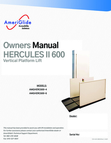
ABCG451UP523DN1UP2 90 VDCMotorHercules II 600 Vertical Platform Lift Install Manual www.Ameriglide.com 866-378-66484Optional EquipmentCircuit BreakerContact - N.C.Contact - N.O.Push ButtonSwitch - N.O. held closedSwitch - N.C.4 Terminal Strip ConnectionLegend:15 AmpC.B.L2 L1RED50W-50Ω D-451312SAF524UP2DN1DNBLK110VAC3 hDownKeySwitch5CSafetyNutNONCCCCall SendUp2NCCNCSafety Pan Switches2C2NCCFinal LmtNCOpt. FlowSwitch342121UP2222DN8A2A21110NOCCBtm LmtNCTop LmtNC144111 REV CSCHEMATIC, RPL ACA2DNUPSAFA1A1A1Top InterlockSolenoid11ABCDP/N: 630-00047 RevB 1151919 // 24110 VAC
Hercules II 600 Vertical Platform Lift Install Manual www.Ameriglide.com 866-378-6648AB42Call Send #49300Call SendTravel Cable #44029Platform Control#49218Safety Nut HRNS #44009EmergencyStopC144111 REV CWIRING DIAGRAM, RPL ACGate CallSend HRNS#44012SOL24VAC110VAC3NCFinalLimitGate Extension HRNS #44014NONONCLowerLimitNCGateClosedCall SendUpperLimitGate InterlockHRNS #44013CNCLimit Switch HRNS #440071NCCNCSafety PanCNCCC50W-50Ω2Safety Nut HRNS #44011C3SafetyNutNO20 // 24PlatformControlD4ABCDP/N: 630-00047 RevB 11519Opt. FlowSwitch15 AmpC.B.3 AmpC.B.90 VDCMotor
ABCNCGateClosed6KeySwitch4Optional EquipmentCircuit BreakerContact - N.C.Contact - N.O.Push ButtonSwitch - N.O. held closedSwitch - N.C.4 Terminal Strip ConnectionLegend:7EmergencyStopDown13CCCSafety NutNONCCall SendKeySwitchUpNCCNCCNCFinal LmtNCCCSafety Pan Switches233NCCBATTERYCHARGER24 VDC4NCA1A23A1A1DN12 VDC12 VDCSAFD2A2830 AmpU2A2A1UPSAFOpt FloatSwitchA1Top InterlockSolenoid- -A2D210NOCU2A2Top LmtNC2112CBtm LmtNC1G -M M 12VPWMMOTORSPEEDCONTROL3 AmpDNUPDNUP24VDCMotorBLKRED 4UPDN144121 REV DSCHEMATIC, RPL DC1ABP/N: 630-00047 RevB 11519Hercules II 600 Vertical Platform Lift Install Manual www.Ameriglide.com 866-378-664821 // 24
Hercules II 600 Vertical Platform Lift Install Manual www.Ameriglide.com 866-378-6648ABGNONONCNC-A2A150W-3Ω C4C --24 VDCMotorNCNC NONO-25 A33A22Call Send #49300Call SendTravel Cable #44029Gate Extension HRNS #44014NCCR2 - "DOWN"NOLimit Switch HRNS #44007Gate CallSend HRNS#44012Gate InterlockHRNS #440131EmergencyStop144121 REV DWIRING DIAGRAM, RPL DCPlatform Control#49218Safety Nut HRNS #44009SOL12 NCNOGateClosedCall SendNCCNCCNC12 VDC3COMSafety Nut HRNS #44011CCNCCNCSafety PanCNCC54321SafetyNutNO CCNOC BATTERYCHARGER24 VDC-A2A1NONCNCNO COM 22 // 24- PlatformControl-4ABP/N: 630-00047 RevB 11519COptionalFloat SwitchSAFETYCR1 - "UP"
P/N: 630-00047 RevB 11519NOTES:Hercules II 600 Vertical Platform Lift Install Manual www.Ameriglide.com 866-378-664823 // 24
P/N: 630-00047 RevB 11519
4 // 24 Hercules II 600 Vertical Platform Lift Install Manual www.Ameriglide.com 866-378-6648 P/N 630-00047 RevB 11519 LIFT SPECIFICATIONS SPECIFICATIONS Payload Capacity 600lb Height Hercules 400 - 53" Hercules 600 - 77" Foot Print 50" x 64" Platform Size 36" x 48" Input Voltage 120VAC - 15A grounded circuit Control Voltage 24VAC