Transcription
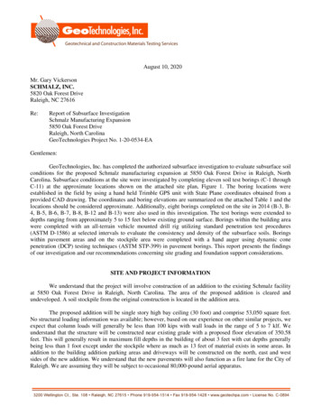
August 10, 2020Mr. Gary VickersonSCHMALZ, INC.5820 Oak Forest DriveRaleigh, NC 27616Re:Report of Subsurface InvestigationSchmalz Manufacturing Expansion5850 Oak Forest DriveRaleigh, North CarolinaGeoTechnologies Project No. 1-20-0534-EAGentlemen:GeoTechnologies, Inc. has completed the authorized subsurface investigation to evaluate subsurface soilconditions for the proposed Schmalz manufacturing expansion at 5850 Oak Forest Drive in Raleigh, NorthCarolina. Subsurface conditions at the site were investigated by completing eleven soil test borings (C-1 throughC-11) at the approximate locations shown on the attached site plan, Figure 1. The boring locations wereestablished in the field by using a hand held Trimble GPS unit with State Plane coordinates obtained from aprovided CAD drawing. The coordinates and boring elevations are summarized on the attached Table 1 and thelocations should be considered approximate. Additionally, eight borings completed on the site in 2014 (B-3, B4, B-5, B-6, B-7, B-8, B-12 and B-13) were also used in this investigation. The test borings were extended todepths ranging from approximately 5 to 15 feet below existing ground surface. Borings within the building areawere completed with an all-terrain vehicle mounted drill rig utilizing standard penetration test procedures(ASTM D-1586) at selected intervals to evaluate the consistency and density of the subsurface soils. Boringswithin pavement areas and on the stockpile area were completed with a hand auger using dynamic conepenetration (DCP) testing techniques (ASTM STP-399) in pavement borings. This report presents the findingsof our investigation and our recommendations concerning site grading and foundation support considerations.SITE AND PROJECT INFORMATIONWe understand that the project will involve construction of an addition to the existing Schmalz facilityat 5850 Oak Forest Drive in Raleigh, North Carolina. The area of the proposed addition is cleared andundeveloped. A soil stockpile from the original construction is located in the addition area.The proposed addition will be single story high bay ceiling (30 foot) and comprise 53,050 square feet.No structural loading information was available; however, based on our experience on other similar projects, weexpect that column loads will generally be less than 100 kips with wall loads in the range of 5 to 7 klf. Weunderstand that the structure will be constructed near existing grade with a proposed floor elevation of 350.58feet. This will generally result in maximum fill depths in the building of about 3 feet with cut depths generallybeing less than 1 foot except under the stockpile where as much as 13 feet of material exists in some areas. Inaddition to the building addition parking areas and driveways will be constructed on the north, east and westsides of the new addition. We understand that the new pavements will also function as a fire lane for the City ofRaleigh. We are assuming they will be subject to occasional 80,000-pound aerial apparatus.
Schmalz, Inc.Re: Schmalz Manufacturing ExpansionAugust 10, 2020Page: 2SUBSURFACE CONDITIONSGeneralized subsurface profiles prepared from the test boring data are attached to this report as Figures2A and 2B to graphically illustrate subsurface conditions encountered at this site. More detailed descriptions ofthe conditions encountered at the individual test boring locations are then presented on the attached test boringrecords.Subsurface conditions on the site were characterized by near surface topsoil which generally extended todepths of 2 to 12 inches below existing grade. Many of the borings encountered near surface fill that consistedof sandy stiff to very stiff clay. Traces organics were observed in some of the fill. Penetration resistances in thenear surface fill varied from 10 to 29 blows per foot (bpf). An exception was encountered at boring C-11,completed on top of the stockpile. That boring encountered fill material to a depth of 14 feet below the top of thestockpile. The upper 2 feet of fill consisted of silty sand; however, below 2 feet the material consisted of topsoil,mixed with clay, silt, sand and heavy organics. The material was very saturated at the time of our investigation.The topsoil and fill was underlain by residual soils that have formed in place by weathering of the parentbedrock. The residual soils generally consisted of stiff to very stiff clay that transitioned to stiff to hard silts withoccasional areas of sand. Penetration resistances in the residual soils varied from of 13 to 35 blows per foot (bpf)and DCP resistances varied from 11 to in excess of 15 blows per increment (bpi). The residual soil wasencountered to the 15-foot maximum boring depth.Groundwater was not encountered in the borings at the time of boring completion. However, the nearsurface soils are fine grained materials and the site is conducive to the development of a shallow perchedgroundwater condition following periods of inclement weather. Additionally, regional groundwater levels willfluctuate with seasonal and climatic changes and may be different at other times.RECOMMENDATIONSThe following recommendations are made based upon a review of the attached test boring data, ourunderstanding of the proposed construction, and past experience with similar projects and subsurface conditions.Once site development details including structural loads and proposed grades are available, that informationshould be provided to GeoTechnologies so that our recommendations can be confirmed, extended, or modifiedas necessary. Additionally, should subsurface conditions adverse to those indicated by this report be encounteredduring construction, those differences should be reported to us for review and comment.Site Grading Consideration. Site grading should initially begin with the removal of the existingstockpile (considered unsuitable), all topsoil and vegetation from within the limits of the proposed newconstruction. We anticipate that topsoil thicknesses will generally be about 2 to 12 inches. Once stripping iscompleted, we recommend that any areas at grade or designated to receive fill be proofrolled with a partiallyloaded dump truck or similar piece of rubber tired equipment. Any areas which rut or pump should be undercutand repaired under the direction of the engineer. At the time of our visit to the site, the near surface soilsappeared to be at or below optimum moisture content. By scheduling grading during the warmer summermonths of the year, near surface moisture contents will likely be lower which will help minimize instability andthe need for undercut repairs.The on-site soils, excluding the stockpile and topsoil, should be suitable for reuse as structural fillprovided compaction moisture is maintained near optimum during placement. If off-site borrow is required, a
Schmalz, Inc.Re: Schmalz Manufacturing ExpansionAugust 10, 2020Page: 3low plasticity clay, silt, or sand with Unified Soil Classifications of CL, ML, SM, and SC may be imported foruse as structural fill. The more micaceous soils that were encountered are somewhat elastic and will requiregood techniques by the grading contractor to achieve proper compaction. All new fill should be compacted tonot less than 95% of the standard Proctor maximum dry density except in the final foot where this requirementshould be increased to 98% of the standard Proctor maximum. We recommend that all fill be moistureconditioned to within 2% of optimum moisture content during compaction operations to facilitate compactionand to maintain stability of the fill section.Excavation Consideration. No shallow partially weathered rock or rock was encountered in the boringsand difficult excavation is not expected to be a significant factor during site grading operations.Retaining Wall Construction. Any rigid concrete retaining walls constructed on the site should bedesigned for an equivalent fluid pressure of 50 pcf. For this value to be applicable, any fill materials placedwithin 4 feet of the walls will need to be compacted with lighter hand held equipment and no heavy equipmentshould be operated within that zone to prevent overstressing of the wall. Additionally, the walls should bedesigned with a sand filter or specialty drainage material against the back side of the walls which is connected toa foundation drain to prevent the build-up of hydrostatic pressures behind the wall. The drain should bedaylighted to a down gradient area on the project site. No highly plastic clay should be placed as fill behind theretaining walls.For segmental retaining walls, we recommend that on-site soils be excluded from the reinforced zone.Local materials which are readily available and will be suitable for use within the reinforced zone would includeCABC base course stone or quarry screenings which are all available from area quarries.Foundation Support Considerations. Following completion of site grading operations, we recommendthat the foundations be designed for a maximum allowable bearing pressure of 3,000 psf. All wall and columnfoundations should have minimum dimensions of 18 and 24 inches, respectively. Additionally, all foundationsshould bear a minimum of 18 inches below grade for frost protection. We recommend that all foundationsubgrades be inspected by an engineer prior to concrete placement to verify adequate bearing capacity. This isparticularly important due to the existence of previous filled material placed on portions of the site.In order to estimate settlements for column loads, GeoTechnologies utilized the FHA method whichcorrelates material types and standard penetration resistances to soil compressibility. The results of our analysesare presented on the attached Figure 3. Based on our analysis, it appears that column loads of up to 100 kips canbe supported on shallow foundations with maximum settlements not exceeding one inch. If slightly highercolumn loads are anticipated, it is possible that settlements could be reduced some by use of stone replacementtechniques.Seismic Design Considerations. GeoTechnologies evaluated seismic design considerations utilizing thesoil test boring data and the information within the North Carolina Building Code. Based on the soil test boringscompleted on this site and deeper borings completed on nearby projects, it is our opinion the site will fall in thesite class definition of "D".Pavement Design Considerations. The site will provide adequate support for properly designed andconstructed pavement sections. No CBR testing was completed; however, based on our experience with similarsoils, we expect that the on-site subgrades will exhibit a design CBR value of approximately 3 to 5%. A typicalpavement section for these type of soils and this type of facility would consist of 2 inches of asphalt overlying 6
Schmalz, Inc.Re: Schmalz Manufacturing ExpansionAugust 10, 2020Page: 4inches of stone in areas subject to only light traffic such as car parking stalls and a section consisting of 3 inchesof asphalt over 8 inches of stone in primary drive areas. This assumes that no more than 2 garbage trucks perweek and one fire truck per month will operate on the pavements.For the dumpster area, it is recommended that a concrete pad with a minimum thickness of 6 inches of4,500 psi concrete be placed on 4 inches of CABC base course stone to better handle the heavy front wheelloads of the trash trucks during tipping operations. Construction joints should be cut in the concrete pad asrecommended by ACI.The most important factors affecting pavement life in the area of the site are the condition of thesubgrade immediately prior to base course stone placement and post-construction settlement. We recommendthe subgrade of all pavement areas be proofrolled and any yielding areas identified and repaired during theinitial grading operations. Additionally, all subgrade soils should be recompacted to a minimum of 98% of thestandard Proctor maximum dry density immediately prior to base course stone placement. We recommend thatall pavement areas be properly graded to promote runoff of water and to prevent ponding of water on thepavement surface which can lead to eventual saturation of the subgrade soils and a loss of pavement support.Due to the potential for shallow perched groundwater conditions following periods of inclement weather, werecommend consideration be given to placing a strip drain or conventional French drain on the uphill side ofpavements and adjacent to landscaped areas to reduce the potential for saturation of subgrade soils and basecourse stone immediately adjacent to natural areas.SUMMARYIn summary, the soils at the site are moisture sensitive, and we recommend grading the site during thewarmer summer months of the year to help minimize earthwork difficulties. The results of our analyses indicatethat column loads of up to 100 kips can be supported on shallow spread footings, designed for a contact pressureof 3,000 psf, with total settlements of about 1 inch.GeoTechnologies, Inc. appreciates the opportunity to provide you with our services during this phase ofthe project. Please contact us if you should have questions regarding this information or if we may be of furtherassistance.Sincerely,GeoTechnologies, Inc.David L. Israel, P.E.NC Registration No. ub.docx
Schmalz, Inc.Re: Schmalz Manufacturing ExpansionAugust 10, 2020Page: 5TABLE 1Summary of Boring Coordinates and ElevationsBoring #C-1C-2C-3C-4C-5C-6C-7C-8C-9C-10C-11State Plane Coordinates 691412122392Elevation 5
6C-7C-8C-10Previous BoringsCurrent BoringsFigure 1
GENERALIZED SUBSURFACE PROFILEElevation (Feet)LEGENDLow Plasticity Clay365C-11L
Raleigh, NC 27616 Re: Report of Subsurface Investigation Schmalz Manufacturing Expansion 5850 Oak Forest Drive Raleigh, North Carolina GeoTechnologies Project No. 1-20-0534-EA Gentlemen: GeoTechnologies, Inc. has completed the authorized subsurface investigation to evaluate subsurface soil conditions for the proposed Schmalz manufacturing expansion at 5850 Oak Forest Drive in Raleigh


