Transcription
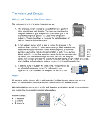
Investigation of leak detection systems for saltwater transmission linesMohammad Reza Boroomand1,* , Nasim Safar Razavizadeh2 , Ahmad Eshghi21Department2Departmentof Civil Engineering, Faculty of Engineering, Tafresh University, Tafresh, Iran.of Research & Development, Omran Mohit Zist Consulting Engineers Company, Tehran, Iran.GRAPHICAL ABSTRACTHardware-based methodsProjectspecificationLeak detectionsystemsRecommended methodFiber optic sensorsSoftware-based methodsARTICLE INFOABSTRACTArticle history:Received 30 June 2021Reviewed 1 September 2021Received in revised form 6 October 2021Accepted 8 October 2021Available online 9 October 2021The use of a proper leak detection system in pipelines is of crucial importance inwater transmission systems. In these methods, we should consider the time andaccuracy of leak detecting procedure for preventing energy loss and reducingenvironmental impacts. In these days, seawater transmission lines are used forcooling systems, and for injecting water into the oil wells to improve oil recovery.Due to the more environmental impacts of saltwater, the leak detection systemmust have appropriate accuracy and speed in leak detection. The purpose of thispaper is to choose a leak detection system for a saltwater transmission line. Firstof all, the specifications of different leak detection systems are provided. Finally,according to the mentioned project conditions, the most suitable method -fiberoptic system- is recommended for these conditions. The most importantadvantages of this system are high accuracy, rapid leak detecting, and the abilityof online monitoring of other parameters, such as temperature distribution ordetecting intrusion into the buried line areas. These abilities result in improvingsafety and optimizing operating costs.Keywords:Leak detectionPipelinesFiber opticLeak localizationSaltwater transmission linesArticle type: Research Article The Author(s)Publisher: Razi University1. IntroductionOne of the methods to improve oil recovery is to inject seawaterinto oil wells by draining water from the sea and transferring it to theoil fields. The saltwater around the line can pose many environmentalimpacts, such as the destruction of farmland and living things, so it isessential to detect leaks quickly and accurately along the seawatertransmission lines to oil fields. So far, different methods have beenproposed and used for leak detection. These methods are usuallydefined in two parts:-Methods based on external effects (hardware).-Computational methods (software).Li et al. (2021) have presented a leak detection method based onactive thermometry and fiber Bragg grating (FBG) based quasidistributed fiber optic temperature sensing. (Li et al. 2021). Adegboyeet al. (2019) studied the different techniques of leak detection inpipelines and presented the strengths and weaknesses of each. Also,in this paper, a suitable technique for different conditions isrecommended (Adegboye et al. 2019). Golmohamadi (2015)introduced various leak detection methods (software-based andhardware-based) and studied two methods for detecting leaks intransmission lines. First of all, hardware-based method which inspects*Correspondingthe pipe by sending supersonic wave through the transmission lines.This method has tested in several pipes with different conditions andhas provided excellent outcomes in short pipes. Secondly, softwarebased method that is rely on a hydraulic model of the pipe. Accordingto the results of this study, the second method has high accuracy forlong pipes (Golmohamadi. 2015). Boostani et al. (2015), comparedleak detection methods based on optimization. A MATLAB codedeveloped on an algorithm with a minimized objective function andthe relationship between pressure loss and potential leakagelocations. The results comparison of the observed data using theoptimal method of leak detection techniques showed that in additionto choosing the appropriate way and calibration of the model, toestimate more accurately the location and amount of the leakage inthe pipeline, field surveys and piezometer readings should beperformed to determine the consumption pattern of the study area toidentify the maximum number of unauthorized branches (Boostaniand Khodashenas. 2015). Moavenian et al. (2011) two online leakdetection methods were designed and simulated based on massbalance. The results showed that the technique could increase thesensitivity to leak detection from day to minute (Moavenian andKhorram. 2011). Hang-Eun Jeo et al. (2018) studied on optical fibersensors. In this paper, the optical fiber sensors employed inauthor Email: boroomand@tafreshu.ac.irHow to cite: M.R. Boroomand, N. Safar Razavizadeh, A. Eshghi. Investigation of leak detection systems for saltwater transmission lines, Journal of AppliedResearch in Water and Wastewater, 8 (2), 2021, 107-112.
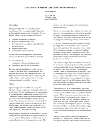
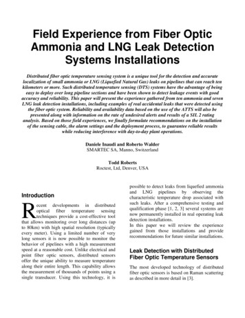
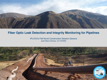
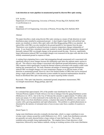
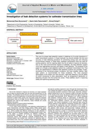
Boroomand et al. / Journal of Applied Research in Water and Wastewater 8 (2) 107-112environmental monitoring are summarized for an understanding oftheir sensing principles and fabrication processes. Numerous specificapplications in petroleum engineering, civil engineering, andagricultural engineering are explored, followed by a discussion on thepotentials of OFS (Optical Fiber Sensor) in manufacturing (Jeo et al.2018). Research by Glisic and Inaudi (2003) reported several fieldapplication examples of fiber optic sensors, including leak detectingon saltwater and gas pipe networks, strain to monitor on gas pipenetworks, and merged strain and temperature monitoring oncomposite transmission pipelines, and composite coiled tubing pipes(Glisic and Inaudi. 2003). Due to the environmental conditions of theproject, and the presence of saltwater, that is dangerous for thesurrounding area, this pipeline is considered as an environmentalhazard. In this paper, some types of leak detection methods with theiradvantages and disadvantages have been presented. Finally, thebest leak detection method considering environmental impacts hasbeen chosen.2. Materials and methodsHardware-based and software-based methods are two commontechniques for detecting leak. These methods are also known asexternally and internally systems. Fig. 1 demonstrates theclassification of different leak detection systems (Golmohamadi.2015).Leak detectiontechniquesHardware-based methodsAcousticSoftware-based methodsFiber optic sensorsMass/volume balanceReal time transient modelingCable sensorVapor samplingNegative pressure waveSoil monitoringPressure point analysisDigital signal processingStatisticalFig.1. Different leak detection systems.2.1. Hardware-based methodsHardware-based methods are used to detect the location andpresence of leaks by some instruments which are installed outside ofthe pipeline. These methods provide an excellent sensitivity in leakdetecting and are so accurate in determining the leak location.However, the disadvantages of these methods are that they are toocostly, and they are also too complex to be implemented. As aconsequence, their application is limited to the places which are underhigh-risk condition, such as pipeline systems that are transferring adangerous material near rivers (Murvay and Silea. 2012). Fiber opticsystems, acoustic leak detection, vapor sensing cable, and liquidsensing cable-based systems are some examples of these types ofmethods.2.1.1. Acoustic leak detectingThis method is based on producing an acoustic noise in thelocation of leak presence. Some acoustic sensors installed outside ofthe pipeline detect the internal signal and then make a baseline withparticular characteristics. The self-resemblance of this signal issteadily tracked by sensors. The leakage presence causes a lowfrequency acoustic signal detected by sensors. In case these signal’sfeatures are different from the baseline, the system will alarm (Fuchs.1991). In the leak place, the tracked signal shows a higher amplitude,and it can contribute to detect the leak location. In these methods,cross-correlation is the most general approach in leak detecting. Thisapproach usually depends on tracking the noise signal which happenswhen leakage occurs through the pipe. In the place where theleakage is expected, the leak can be detected by installing sensor onboth sides of the pipeline (Fig. 2).Fig. 2. Acoustic Sensors in Leak Detection (Golmohamadi. 2015).108The leak place can be recognized by speed of sound, durationtime, and the spacing between sensor places. This would bedetermined by solving the following equation (Geiger and Werner.2003):𝑑1 𝑑 𝑐𝑡𝑝𝑒𝑎𝑘2(1)In this equation, d1 is the spacing between the sensor (1) to theleakage point, d is the spacing between two sensors, c is the soundspeed, and tpeak illustrates the time delay in the delivering of similarfrequencies to every sensor. The efficiency of this method relies onthe spacing between the sensor points, d. clearly, all variables of thisequation can be determined from the experiment. The performanceand precision of this system does not depend on the operator skills(Ghazali. 2012). Regarding to the benefits of using this method, thesystem can be monitored continuously. Although acoustic signals areappropriate in detecting the leakage location and the estimating ofleak’s size, in some cases, high background noise, such as noisewhich is created by pump equipment or vehicles, can affect the realleakage signal (Murvay and Silea. 2012). In addition, an importantproblem for the limited application of this method is its financialissues; installing numerous sensors that are essential in inspecting ofthe long pipelines according to this method is dramatically costly(Golmohamadi. 2015).2.1.2. Fiber optic sensorsThis technique includes the installation of a fiber optic cable alongthe whole length of the pipe. The material to be measured get in touchwith the cable change the temperature of the cable. The distributedfiber optic temperature sensing technique offers the possibility tomeasure temperature along the pipeline. The principle of pipeline leakdetecting in this technique depends on a simple concept: when a leakoccurs at a particular place along the pipe, the distribution oftemperature around the pipe changes. This change is localized bothin space and in time and makes the algorithmic detecting of leakagerelatively simple to implementation. The base of the temperaturedisturbance around the pipe relies on the kind of pipe and the areaaround it. Fig. 3 shows the position of the fiber optic sensor cablearound the pipeline (Niklès et al. 2004).The most usual impacts are as the following: The leaked liquid material higher temperature than the soil (Fig. 4a).
Boroomand et al. / Journal of Applied Research in Water and Wastewater 8 (2) 107-112 The leaked gas creates a local cooling owing to pressure release(Fig. 4-b). The leaked liquid affects the thermic features of the surroundingsoil, especially thermic capacity, and changes the typical day/nighttemperature cycles. A warm plume is created in pipe surrounding In the multiphase pipelines, a combination of the mentionedimpacts can happen.Apart from that, it is not very practical for installing in longtransmission lines due to the equipment price that is too expensive.The second disadvantage of this system is its problem in pipelineswhich are above ground or grave sites.Fig. 6. Leak Detecting by Vapor Sensing Tube Method.Fig.3. Specific positions of the fiber optic sensor cable around thepipeline.2.1.4. Liquid sensing cablesThese cables are installed beside a pipe, and the most importanttask of them is an inspection of changes in energy pulses which haveoccurred because of impedance differentials. Energy pulses transmitconsistently along the cable. A monitoring unit receive the reflectionsof energy pulses and create a map of them and then, save this map ina memory. The liquids on the sensor cable will affect its electricalfeatures. This effect will lead to a difference in the reflection energypulses at that place. This method is used to identify the place of aprobable leakage. The time difference between input and reflectedpulse would determine the exact location. (Golmohamadi. 2015). Thismethod is applicable to detect multiple leak presence and alsosuitable in short pipelines.2.1.5. Soil monitoringFig. 4. Thermal behavior of warm (a) and cooling (b) fluid at the pointof leakage.The mentioned impacts affect the perfect cable localizationaround the pipe. In the underground liquid pipe, the most perfectplace for the sensing cable is under the pipeline, however not in directconnection. (Mirzaei et al. 2013) (See Fig. 5).This system uses a cheap and safe gaseous detector into thepipe. This detector is identified as a very volatile gas that escapesfrom the pipe where the leakage happens. The investigation of thesoil above the pipe helps us to predict the existence of the leak and itsplace. This method provides some benefits, such as making low falsealarms and also the ability to detect tiny leaks. However, the methodis too expensive due to the fact that the detector should be injectedthrough the pipeline permanently during the detecting process. Inaddition, this method is not practical in case of uncovered pipes(Golmohamadi. 2015).2.2. Software-based systemsFig. 5. Leak detection in buried liquid pipeline.The changing in detecting time and the volume reflects thevarious local properties and in specific: Permeability and soilcompaction, spacing between the leak and the sensor point andvariation between temperature made by leak and the soiltemperature. Although there are some disadvantages for fiber opticmethod, such as high costs, which limit the use of this method forpipeline monitoring, insensitivity to electromagnetic interference is oneof the main advantages of fiber optic method (Ghazali. 2012).2.1.3. Vapor or liquid sensing tubesThis method includes the implementing of a tube along the entirelength of the pipeline. In case of leakage occurrence, the materialtransferred by the pipe affects the tube. In case of leak occurrence,some gas sensors at the end of the tube detects changes in gasconcentration along the tube. The size of this change in gasconcentration indicates the amount of the leakage. An electrolytic cellis attached to the inspected pipeline which diffuses a particularamount of test gas through the tube persistently. This gas goesthrough the entire length of the tube and when moves through theinspector section generates a final peak. The location of the leak isdefined by obtaining the ratio of final peak delivery to leak peakdelivery (Golmohamadi. 2015). Fig. 6 illustrates this method. As adrawback of this technique, the speed of leak detecting is deficient.These methods rely on the assessment of pipeline hydrauliccharacteristics, such as flow and pressure. In general, the impact ofthese systems relies on the uncertainties related to the system’sproperties, operating properties, and gathered information.2.2.1. Mass-volume balanceThis is a technique based on the principle of conservation ofmass. The principle states that the amount fluid enters the pipesection is equal to the amount of left fluid. The flow going into andexiting the pipeline networks can be measured easily. Any observedvariation between upstream and downstream hydraulic parametersmeasurement which are larger than accepted threshold demonstratethe presence of the leakage (Murvay and Silea. 2012). This techniqueis susceptible to pipeline facilities’ precision. One important drawbackof this technique is the assuming of a steady condition. Therefore, thedetecting time should grow for avoiding the possible false alarm.Hence, the response time to the leakage will be lasted more. As anexample, a 1 % leak requires about one hour to be detected (Boostaniand Khodashenas. 2015). Moreover, this method is not able to detectthe location of the leak (Ghazali. 2012).2.2.2. Real-time transient modeling (RTTM)This method relies on solving the hydraulic flow models of thepipe using mass, momentum, and energy conservation equations.The discrepancy between the measured and calculated values of theflow determines the leak occurrence. The measurement of hydraulicparameters and temperature at both sides of the pipe are essential for109
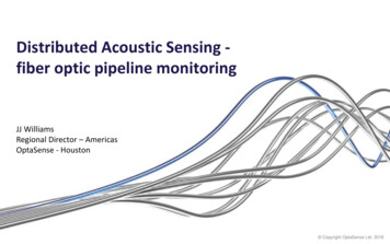
Boroomand et al. / Journal of Applied Research in Water and Wastewater 8 (2) 107-112creating this model. In addition, the design of a perfect system with alow range of false alarm needs a steadily monitoring system toinspect the noise level. This would lead to modification of the model.The main benefit of this technique is the ability of detecting tiny leaks,and it can predict the leak’s size precisely. Apart from that, the delayin time of leakage detecting is insignificant. However, this technique istoo expensive due to the fact that it requires the processing ofmassive data (Golmohamadi. 2015).2.2.3. Negative pressure wave (NPW)When a leak happens, the pressure in pipe drops abruptly at theplace of the leak. This sudden change in pressure produces anegative pressure wave which goes through the pipe with a specifiedvelocity in both direction of the pipe. The negative pressure wave isdetected by two pressure sensors locating at the start point the andend point of the pipe. These sensors can recognize the leakage andlocalize it by measuring the time variation of the delivery times of thenegative pressure wave at each sensor (Golmohamadi. 2015). Themeasured time in this technique is about two minutes, and thelocalizing of the leak has a 2% error. However, this method still is notapplicable in long pipelines (Murvay and Silea. 2012). SensitivitySensitivity (API-1155) is a combined measurement of the leak’ssize and the time needed for making a leak alarm. Minimumdetectable leakage rate and leakage detecting time rely on eachother. Lower minimum leakage detecting rates need longer leakagedetecting times, and higher minimum leakage detecting rates allowlower leakage detecting times. The performance of a leak detectionsystem is defined by using an OCP (Operational Characteristic Plot).There are some important things to note:In long lasted leakage detecting times, for both leak detectionsystem, the minimum leakage detecting rate converges asymptoticallyto a minimum limit value, the lowest possible leakage detecting rate.This parameter is mainly depending on the precision of the flowmeters, and so it is almost not dependent on the leak detectionsystem type. If the detecting time reduces, the minimum leakagedetecting rate grow for both LDS (leak detection system). LDS #1provides a better performance (lower minimum leakage detectingrates) than LDS #2.2.2.4. Pressure point analysis pressure.This technique identifies the presence of leakage by assessingthe pressure data received from the pipe with a statistical trend that istaken in a particular duration along the pipe by monitoring equipment(Ghazali 2012). This technique depends on the principle of thepressure loss resulting of leak occurrence. A leak alarm will generateby the system when the newer data is significantly different from olderrecords. Although this technique may acquire sensitive high accuracy,it is not certainly need exact instrumentation. Hence, the overallinstallation costs are not too expensive. In addition, this technique candetect the happening of leakage, but not the existence of it. Due tothe fact that this technique considers change in pressure value as aleakage signature, it could create errors yielded because of thepressure drop which is not really related to the leakage.2.2.5. StatisticalThis system uses an enhanced statistical method to analyze thehydraulic parameters and temperature measurements of a pipe. Thistechnique is suitable for complicated pipeline systems since it can beinspected steadily for variations in the line equipment. Moreover, thissystem has the ability to localize the leak point. This method also isused for various pipe systems (Murvay and Silea. 2012). The mainpurpose of this method is to detect leaks with minimum number offalse alarms. In addition, it is proper for real-time applications mostlyin pipeline systems in oil industries (Ghazali. 2012). The maindrawback of this method is the noise interfering in the statisticalanalyses which prevents leaks from being detected (Golmohamadi.2015).Fig. 7. Evaluating sensitivity using the operational. AccuracyLDS may provide additional leak information such as leak locationand leak rate. The validation of these leak parameter estimatesconstitutes another measure of performance referred to as accuracy. RobustnessRobustness (API-1155) is described as a measurement of theleak detection system’s ability to continue to operate and providehelpful information, even under unstable conditions, or in a situationwhere data is lost or not accurate. Robust leak detection systemusually can tolerate sensor fails using some kind of redundancyevaluation.2.4. Project specifications2.2.6. Digital signal processingIn this technique, the reflection of the pipe to a particular inputsignal is determined in a specific time duration. Then, this reflection iscompared to the following data. The difference in comparison ofsignal’s properties. This method does not require a pipe model. Themain issue of using this technique for leak detecting is that in thismethod, just leakage happening can be identified, not leak existenceeven the size of the existing leak rises significantly (Murvay and Silea.2012).The aim of this project is to transfer water from onshore to the 4delivery points. For this purpose, two steel buried pipelines aredesigned in parallel with a length of approximately 185 km. in thisproject, the transferring water is raw seawater. In addition, the routelines are near the farmlands, the speed and accuracy in detectingleaks are essential for the environmental considerations. Theoverview of the pipeline route in this project is shown in Fig. 8. In thisproject, various leak detection methods have studied, and accordingto the project conditions, the best method has been chosen.2.3. Requirements to leak detection system (LDS)3. Results and discussionAPI-1155 represent a framework to assess the various leakdetection systems. API-1155 specifies four performance parameters:Various criteria can assess the performance of leak detectionsystems. According to the conditions of the project, the most effectiveapproaches for choosing a leak detection system are the speed ofdetection and also the accuracy in locating the leak point. ReliabilityReliability (API-1155) is described as a way to assess the abilityof the leak detection system to make precise alarms for presence of aleakage on the pipe, while operating within an envelope establishedby the leak detection system design. It follows that reliability is directlyrelated to the possibility- To identify leakage, given when leakage exists, and- To wrongly predict leakage given when no leak has happened.A technique is dependable if it continuously identifies real leakswithout creating false warning.110 The accuracy of the acoustic leak detection method in detectingthe leak location depends on the distance between the twoconsecutive sound sensors. In this project, due to the fact that weneed high accuracy, and also the length of the pipeline is long(185 km), the use of this method is not economical. The acousticleak detection system works by changing the frequency of thesound. Hence, other sounds in the surrounding area can coverthe noise caused by the leak. Besides, this method is not suitable
Boroomand et al. / Journal of Applied Research in Water and Wastewater 8 (2) 107-112 for detecting small leaks having low noise levels. So, the acousticsystem does not meet the requirements of this project.In vapor or liquid sensing tube technique, the leak detectionspeed is deficient, and this method is not suitable for largepipelines due to the high cost of equipment. Therefore,considering the long length of pipeline in this project, this systemis not appropriate.Fig. 8. Pipeline route from pump station to delivery points. The liquid sensing cable system, as the previous system, appliesto short pipelines.The soil monitoring technique is costly because of the need forcontinuous injection of the detector. As a result, it is notappropriate for using in this project.The mass-volume balance method has many false alarms inunsteady flow conditions. Also, it cannot determine the location ofthe leak. This is one of the critical factors in choosing a leakdetection system in this project.The real-time transient modeling (RTTM) system has low falsealarms and quick leak detection, but its locating error is 1 % to 2% of the length of the pipeline. So, where the length of thepipeline is about 185 km, this error is too high, and the method isnot applicable.Negative pressure wave method is not practical for leak detectionin long pipelines. This method is only effective for largeinstantaneous leaks.The basis of leak detection in the pressure point analysis systemis the measurement of the drop in pressure value, so there mightbe many false alarms. In this project, the valves used along theline can cause a drop in pressure values, so this method is notrecommended.In the statistical system, the noise in the surrounding area caninterfere with statistical data, and the system cannot detect allleaks. Also, in this method, the visible leaks are just detectable.Digital signal processing system, like the statistical system, is notapplicable in detecting small leaks, and it is difficult and expensiveto implement, so it is not acceptable in this project.The fiber optic sensors system has the ability to identify tiny leaks(micro leaks), and also its leak detection time is less than oneminute. Due to the operation type of this system, the number offalse alarms is very small, and the leakage point’s localizationerror is less than 1.0 meter.4. ConclusionsAs a consequence, the most suitable method for detecting leak ina long saltwater transmission pipeline, which requires high accuracyand short time for detecting in terms of environmental considerations,is the fiber optic method. Table 1 shows the specifications of thissystem.Table 1. Fiber optic sensor specifications.IndexFiber optic sensorSensitivityAbility to detect the very small leak (micro leak)Leak detection Less than a minutetimeReliabilityVery few false alarms (less than two times ayear)MaintenanceNeed to maintain and repair cablesAccuracyLess than 1.0mThe distributed fiber optic monitoring system creates a continuousmonitoring of pipes, improving their safety, and enabling the pipeoperator to be informed and make proper decisions on the operationsand maintenance of the pipe. In specific, this system allows thefollowing monitoring functions (Glisic and Inandi. 2007): Distributed Temperature MonitoringAllows the measure of the temperature distribution along thepipeline. This information is used for optimizing operationalparameters. Leakage DetectingDuring the detection of temperature disturbance, it is possible toidentify small leaks that cannot be identified by conventionalvolumetric methods. In addition, the ability to localize the accurateplace of the leakage enables an immediate response at this place,reducing downtime and ecological results. Intrusion DetectingBased on a same method, concentrating on localized strain andtemperature variations, the existence and place of an accidentalintrusion can be identified. This allows preventive action before theintruder can damage the pipe. Distributed Strain and Deformation MonitoringThis provides information about the strain variation along the pipe.This is exclusively helpful at crucial places where movements causedby natural changes, such as earthquakes, or human actions canintroduce potentially dangerous strain conditions to the pipe. Inaddition, this approach has the ability of detecting wall-thicknessvariations along the pipeline, because of corrosion or erosion. Thefeatures and applications of the fiber optic system are summarized inTable 2.Table 2. The features and applications of the fiber optic system.FeaturesApplicationsDistributed measurement ofPipeline leak detectionstrain & temperatureHigh spatial resolutionStrain or curvature monitoring ofpipelineExtended rangeWater industry / water pipelinesLong-term stabilityOil & gas pipelinesTransportable systemCoal miningSingle-fiber, single-end orSlope stabilityloop operationDam seepage monitoringCost effective for large no. of Road & rail strain and settlementmeasurement pointsIntrinsically safeStructural monitoringRecent advances in fiber-optic technology make it possible tomonitor more than 60km of line length with just one measuring device.This length can be extended up to 300km using optical amplifiers.Pipeline monitoring can prevent fracture and detect the exact locationin the event of a fault, and also optimize maintenance programs. As aresult, with the use of this system along the pipelines of this project,with the increase of safety, the operating costs will be optimized, andthe waste of economic resources will reduce. For the future studies, itis recommended to implement a pilot to compare the real results withthe fiber optic method characteristics.NomenclatureFBGLDSNPWRTTMFiber Bragg GratingLeak Detection SystemNegative Pressure WaveReal-Time Transient ModelingReferencesAdegboye M.A., Fung W.K., Karnik A., Recent advances in pipelinemonitoring and oil leakage detection technologies: principles andapproaches, Sensors 11 (2019) 1-36.API-1155, Evaluation methodology for software-based leak detectionsystems standard, First Ed, American Petroleum Institute (1995).Boostani A., and Khodashenas S.R., Studying a leakage detectionmethod in pressurized water networks based on the pressure–leakage relation, Journal of Water and Sustainable Development 2(2015) 59-66.Fuchs H.V., Ten years of experience leak detection by acoustic signalanalysis, Applied Acoustics 33 (1991) 1-19.Geiger G., Werner T., Matko D., Leak detection and loca
dangerous material near rivers (Murvay and Silea. 2012). Fiber optic systems, acoustic leak detection, vapor sensing cable, and liquid sensing cable-based systems are some examples of these types of methods. 2.1.1. Acoustic leak detecting This method is based on producing an acoustic noise in the location of leak presence.