Transcription
Field Experience from Fiber OpticAmmonia and LNG Leak DetectionSystems InstallationsDistributed fiber optic temperature sensing system is a unique tool for the detection and accuratelocalization of small ammonia or LNG (Liquefied Natural Gas) leaks on pipelines that can reach tenkilometers or more. Such distributed temperature sensing (DTS) systems have the advantage of beingeasy to deploy over long pipeline sections and have been shown to detect leakage events with goodaccuracy and reliability. This paper will present the experience gathered from ten ammonia and sevenLNG leak detection installations, including examples of real accidental leaks that were detected usingthe fiber optic system. Reliability and availability data based on the use of the ATTS will also bepresented along with information on the rate of undesired alerts and results of a SIL 2 ratinganalysis. Based on those field experiences, we finally formulate recommendations on the installationof the sensing cable, the alarm settings and the deployment process, to guarantee reliable resultswhile reducing interference with day-to-day plant operations.Daniele Inaudi and Roberto WalderSMARTEC SA, Manno, SwitzerlandTodd RobertsRoctest, Ltd, Denver, USAIntroductionRecent developments in distributedoptical fiber temperature sensingtechniques provide a cost-effective toolthat allows monitoring over long distances (upto 80km) with high spatial resolution (typicallyevery meter). Using a limited number of verylong sensors it is now possible to monitor thebehavior of pipelines with a high measurementspeed at a reasonable cost. Unlike electrical andpoint fiber optic sensors, distributed sensorsoffer the unique ability to measure temperaturealong their entire length. This capability allowsthe measurement of thousands of points using asingle transducer. Using this technology, it ispossible to detect leaks from liquefied ammoniaand LNG pipelines by observing thecharacteristic temperature drop associated withsuch leaks. After a comprehensive testing andqualification phase [1, 2, 3] several systems arenow permanently installed in real operating leakdetection installations.In this paper we will review the experiencegained from those installations and providerecommendations for future similar installations.Leak Detection with DistributedFiber Optic Temperature SensorsThe most developed technology of distributedfiber optic sensors is based on Raman scatteringas described in more detail in [3].
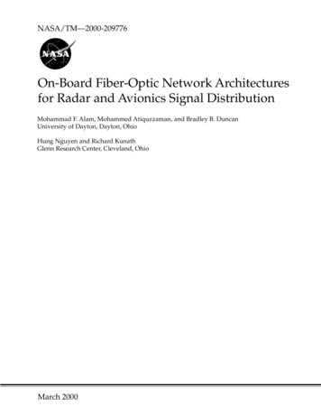
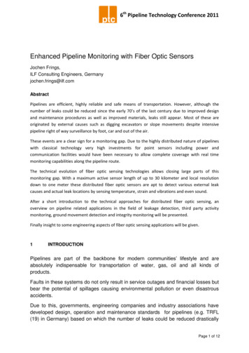
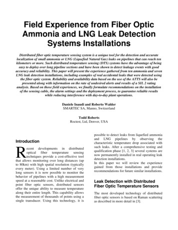
The typical components of a distributedtemperature sensing system are the following: Sensing cable to be installed along thepipeline. Interrogator. Multiplexer to allow multiple fiber opticcables to be measured from one interrogatoror to provide interrogation from both ends ofthe same cable for redundancy. Data analysis software for automatic detectionof leaks. Relay module used to transfer alarminformation to other plant control systems(e.g. to initiate automated emergencyshutdown sequence). SCADA Interface. Automated Trip Testing System. User graphical interface that shows the exactlocation of a leak.A typical rack cabinet containing two fullyredundant is shown in Figure 1, while Figure 2illustrates a typical cable installation. Figure 3shows the graphical user interface, providinginformation about pipe route and leak location.SensingCableFigure 2: Red cable installation under pipeFigure 3: Example of user interface showinglocation of event, e.g. leak detectionFigure 1: Fully redundant leak detection systemThe basic principle of pipeline leak detectionthrough the use of distributed fiber optic sensingrelies on a simple concept - when a leak occursat a specific location along the pipeline, thetemperature distribution around the pipelinechanges. In the case of Ammonia and LNG, weobserve a rapid and localized drop oftemperature
Automated Trip Testing SystemOne of the most effective tools to insure an highlevel of availability is the addition of anautomated testing system. The ATTS(Automated Trip Testing System) is a device,fully independent from the data acquisitionsystem, which can create an artificial leakagealong the sensing cable and verify the correctresponse of the alert system (see Figure 4).Every hour, the ATTS automatically cools orheats 1m section of optical fiber at a rate similarto the one observed in the case of real leakageand observes the signal coming from the relaymodule to verify alarm triggering. A PLC(Programmable Logic Controller) is used toverify that for each testing cycle initiated by theATTS, a corresponding alert is raised by theDTS. This configuration allows a higher level ofself-diagnostic capability and insures that anyissue in the system is rapidly detected.This system configuration, including DTS,Multiplexer, sensing cable, relay module, leakdetection software and ATTS, has received aSIL 2 certification with the followingparameters:Safety Integrity"hazardous" failure(revealed)"hazardous" ilure(unrevealed)Diagnostic CoverageSafe Failure FractionSIL 2rate 7.73 10-6 per hourrate 0.12 10-6 per hourrate 0.47 10-6 per hour Despite no valid temperature condition,deliver a loop disconnect output (open relay)The rating assumes that the user can recognizethe hourly “healthy” signal generated by theATTS, by means of some logic function and toprovide and act on a positive alarm in the eventof no diagnostic signal. Thus, all failures withinthe ATTS, and those within the MUX, can onlyresult in loss of hourly diagnostic functionwhich, in itself, should be treated as a revealedfailure. Failures not revealed by the use ofATTS are assumed to be revealed by an annualproof test which also covers the diagnosticfeatures.Figure 4: Example of simple leak detectionsystem with additional self-testing capabilityThe overall integrity claim, which derives fromthe very high diagnostic coverage obtained,supports this safety-integrity assessment. As aconsequence, both the unit and the simulatedbased diagnostic unit must be subjected to theannual periodic proof test.Field Installationsrate 098% 98%The failure rate was evaluated in respect of thefollowing failure modes: In response to a valid temperature conditionat the fiber cable, failure to deliver a loopdisconnect output (open relay)The leak detection system described in theprevious chapters has been installed in a numberof plants in Europe, as illustrated in thefollowing tables.
Ammonia pipelinesPlantLearningsCountryYear ofinstall.Approx.lengthof pipeSystemconfigurationItaly20065 km2 x basicFrance201010 km2 x fullyredundantYaraMontoirFrance20132 km1 x fullyredundantYaraPardiesFrance20131.5 km1 x basic ATTSYaraAmbèsFrance20142 km1 x fullyredundantBorealisGrandpuitsFrance20132.5 km1 x oject0.4 km1 x basic (pilottest)23 km14 systemsYaraRavennaYaraHavreLeTOTAL4.2 LNG pipelines and tanksPlantCountryYear ofinstall.Approx.lengthof pipeSystemconfigurationLNG plantpipeUSA2006undisclosedAd-hocLNG JettypipeUSA20072 kmAd-hocLNG neUK20084.5 km1 x fullyredundantLNGtransferhosemonitoringFrance20092 kmAd-hocLNG tankFrance20151 km1 x basicLNGtransferlineFrance20164 km1 x basic ATTSTOTAL7 systemsFor confidentiality reasons, the return ofexperience described in the following chapterswill not make reference to a specific site, butrather summarize the lessons learned across allprojects.Detected leaksFortunately, none of the instrumented plants hassuffered any major ammonia or LNG leak sinceinstalling the fiber optic detection system. Therehave been however two cases where a minorleak was detected.The first instance concerned a very small leakfrom a bolted joint that was discovered duringthe commissioning of one of the systems. Theleak was correctly identified by the system andwas later confirmed by visual inspection. Thisleak was well below the minimum leak rate thatrequires immediate action.A second occurrence concerned a coupling to atransportation vessel that leaked during anammonia transfer operation. Also in this casethe leak was correctly identified by the systemand an alert was generated. The ammoniatransfer was stopped and resumed after fixingthe issue. Figure 5 shows the temperatureevolution at the location of the leak. It ispossible to observe how the temperaturedropped from an initial value of about 20 C(ambient temperature) to about -40 C due to theleak. The location of the leak can be clearlyidentified at meter 887, but a larger section ofcable is affected by the cooling effect of theammonia evaporation cloud.
ATTS dataFigure 7 shows an illustration of temperaturerecording at the location of the cooling zone as afunction of time. It can be observed that with anhourly frequency the apparition of the coolingpeak is easily observable.Figure 5: Temperature distribution along thesensing cable during a leakThe time evolution of the temperature at theleak location can be observed in Figure 6.Figure 6: Temperature evolution at the locationof the detected leakAvailabilityAvailability data from the sites were evaluatedto quantify the reliability of the differentcomponents of the leak detection system. At thetime of writing, the 14 systems that are inoperation have added up 34 years of operation,with an average of 2.4 years per system. Therecorded mean time between failures (MTBF) ofthe individual sensing components wasevaluated to 8 years. The failure and/ormaintenance of the individual sensingcomponents (interrogator, ATTS, server) haveprevented operation of the 34 systems for a totalof 0.9 years, corresponding to an uptime of97%. Considering only redundant system theuptime was 99% (with at least one of the tworedundant systems available).Figure 7: Example of ATTS temperaturerecording at the cooling locationOnce hundreds or thousands simulated leakageevents are generated, it becomes possible tocalculate the probability of answer on demand(% of successful detections) and generatestatistics on the reaction time (average andmaximum delay). For example, a confidencelevel of 2 requires that 99% of the simulatedleaks are correctly detected.The data from the installed ATTS systemscorroborates the availability data presented inthe previous paragraph, respectively 97% forindividual detection systems and 99% forredundant systems. When the systems were inservice, the ATTS triggered an alert in 99.9% ofthe tests, demonstrating the high reliability ofthe ATTS device itself. Those results confirmexperimentally the high availability expectedfrom a SIL 2 certified system compliance.
False alertsThere have been no reported cases of falsealerts, where an alarm was triggered without acorresponding temperature drop. There have,however, been numerous cases of false positiveswhere unforeseen circumstances have triggereda "true" alert that did however not correspond toa real ammonia leak. The main causes of suchfalse positives were the following: Trigger levels: temperature changes thatwould trigger an alert were initially set tooaggressively and have generated falsepositive due to temperature variationinduced by normal plant operation orweather conditions. After an observationperiod, the trigger levels were re-assessedand optimized to eliminate such falsepositives. Singular points: at some locations, extremetemperature changes were recorded due toexternal events. Examples include nearbyfast cooling devices or vapor blows thatwould heat and cool the sensing cables.Those localized points were easily spottedby observing how false positives cumulatedat the same location. It was then easy tocorrect those points by physically shieldingthe cable from the disturbance or adjustingthe trigger levels of those isolated points.Other encountered issuesThe main obstacles that were encountered on thepath to a successful deployment of ammonialeak monitoring system were organizationalrather than technical. One common challenge inmany sites concerned the transfer of systemownership from the project team to theoperational team. In some cases this transfer didnot occur with a sufficient training of the finaloperators. That caused misunderstandings on theway the system works and result in falseexpectations and the system sometimes became“orphan” since nobody was really takingownership of it. In such cases it is possible thatalerts generated by real leaks or warnings aboutfailed components gets un-noticed. To avoidsuch misunderstandings, it is recommended toinvolve the production and maintenance teamsfrom the beginning of the project and carry outin-depth training of all shifts to make sure thesystem functionality is properly understood.In some other cases the opposite problem arose,when the system was transferred too soon toexploitation, before the initial false positiveswere completely eradicated, causing a generalmistrust in the system that had to be reversedlater on. In general, most safety systems thathave no direct benefit on the day-to-day plantactivities need to strike the right balancebetween staying out of the way of normalexploitation and not becoming forgotten andabandoned.In two other sites, damage to the cable wascaused by insufficient training of themaintenance personnel. They simply did notknow how to handle the sensing cable if theyneed to service components supervised by theammonia leak detection system. An earlyinvolvement of the maintenance staff istherefore highly recommended. At another site,the maintenance team was able to inform usabout the most usual maintenance interventionsthat can affect the pipe and ancillary devices. Itwas then possible to install some extra length ofcable at those locations to allow displacing thesensor and easing future maintenance.ConclusionsThe large number of field deployments of fiberoptic based ammonia and LNG leak detectionsystem has allowed learning valuable lessons onthe technical and organizational sides. It waspossible to improve the reliability andavailability of the systems by implementingautomated self-testing capabilities. The datagathered by the 14 systems currently inoperation show an availability of 97%. All casesof non-availability were quickly identified so
that they can be corrected rapidly or alternativesafety measures could be implemented. Thesystem is SIL 2 certified.By monitoring false positives and understandingwhat operational or environmental conditionwould trigger unwanted alerts, it was possible toimprove the leak detection algorithms andstandard thresholds so that only real ammonia orLNG leaks would trigger alerts.Finally, the process for deploying a system to anew site is improved by involving the rightproject and site team and by making sure thatthe system is finally owned by the people usingit daily. Only one real leak of significant(although very small) size was recorded andcorrectly set off an alert.AcknowledgementsWe would like to sincerely thank Yara France,Yara Italy and Borealis France for the nt and qualification phases of thisinnovative leak detection system and for lettingus share the experience gained at their sites. Wewere particularly impressed by the excellentteamwork that could be established betweencompetitors on topics related to process safety.References1. Inaudi D., Belli R., Walder R., 2008,“Detection and Localization of MicroLeakages Using Distributed Fiber , IPC2008, Calgary, Canada.2. Inaudi D., Glisic B., Figini A., Walder R.,2007, “Pipeline Leakage Detection andLocalization Using Distributed Fiber OpticSensing”, Rio Pipeline Conference 2007, Riode Janeiro, Brazil.3. De Bont R., Inaudi D., Walder R., 2015,"Detection and Localization of Leakages inToxic/Flammable Chemicals Pipelines usingDistributed Fibre Optic Sensors", Nitrogen Syngas, 28thInternational Conferenceproceedings.
location of event, e.g. leak detection The basic principle of pipeline leak detection through the use of distributed fiber optic sensing relies on a simple concept - when a leak occurs at a specific location along the pipeline, the temperature distribution around the pipeline changes. In the case of Ammonia and LNG, we

![Fiber Optic - Perimeter Intrusion Detection System [Fopids]](/img/57/foss-presentation.jpg)