Transcription
AN OVERVIEW OF PIPELINE LEAK DETECTION TECHNOLOGIESJonathan FiedlerKROHNE, Inc.7 Dearborn RoadPeabody, MA 01960IntroductionThis paper will provide you with a fundamentalunderstanding of the operating principles of currentlyavailable pipeline leak detection technologies. To startwith we’ll have a look at the topics to be covered: Historical development of pipelinesWhy they are monitored for leaksThe requirements and regulations placed on leakdetection systemsVarious causes of leaksDifferent leak detection methodsIt will also be shown how pipelines are monitoredutilizing leak detection systems which are operated: non-continuouslycontinuously with external measurementscontinuously with internal measurementsThe paper will also familiarize the reader with howsystems localize leaks using various methods. Theadditional functionality that can be realized from a leakdetection system will also be explored. In closing, thereader will gain a better understanding of the uniquechallenges that each methodology presents.HistoryPipelines originated over 5,000 years ago by theEgyptians who used copper pipes to transport clean waterto their cities. The first use of pipelines for transportationof hydrocarbons dates back to approximately 500 BC inChina where bamboo pipes were used to transport naturalgas for use as a fuel from drill holes near the groundssurface. The natural gas was then used as fuel to boil saltwater, producing steam which was condensed into cleandrinking water. It is said that as early as 400 BC waxcoated bamboo pipes were used to bring natural gas intocities, lighting up China's capital, Peking.Today's pipelines originated in the second half of the 19thcentury and since their adoption have grown drastically insize and number. While drilling for water, crude oil wasaccidentally discovered in underground reservoirs. Thiscrude oil was not very popular until simple refineriescame into existence.The oil was transported to these refineries in wooden vatsthat were even transported across rivers via barges pulledby horses. One alternative method of transport was byway of railway tanker cars. However, this meant that theoil supply was controlled by the large railway owners.So, to make transport independent and more reasonablypriced, pipelines were adopted as a more economicalmeans of transportation. The transported oil was boiledoff in refineries to obtain the by-products of naphtha,petroleum, heavy crude oil, coal tar and benzene. Thepetroleum was used as a fuel for lighting and the benzeneproduced was initially considered an unwanted byproduct and was disposed of.This situation changed drastically with the invention ofthe automobile which instantly increased the demand forconsistent and reliable supplies of gasoline and resulted inthe need for many more pipelines. Pipelines todaytransport a wide variety of materials including oil, crudeoil, refined products, natural gases, condensate, processgases, as well as fresh and salt water. Today there aresome 1.2 million miles of transport pipelines around theworld, with some well over 1,000 miles in length. Thetotal length of these pipelines lined up end to end wouldencircle the earth 50 times over.The construction of these longer pipelines with largerdiameters also increased the need for more intelligent leakdetection systems to better detect and localize accidentalreleases. Where it was once enough to have inspectorswalk the length of pipelines and visually inspect forevidence of leaks, today this is no longer possible. Inmany cases, due to the longer lengths and the rigorousruns of remotely located pipelines, physical access maybe limited. Pipelines can run through snowy landscapes,across mountain ranges, along bodies of water, or belocated underground or subsea, even at depths exceeding1 mile.But why is it necessary to implement leak detectionsystems at all? Although they are the most reliable andsafe option compared to other methods of transportation
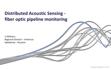
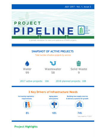
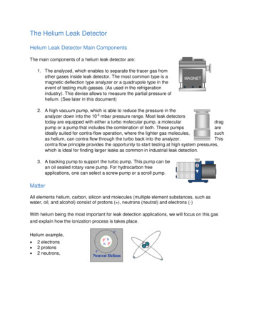
possibilities, accidents and thefts can and do occur withpipelines. In such cases, leak detection systems can helpminimize damage to people, the environment, and thecompany image as well as the high costs for repair,renovation, indemnity, breakdowns and the lost value ofthe liquid or gas that has been released. In addition, thereare also different official regulations related to pipelineleak detection. Let's take a look at them.RegulationsIn many countries it has become necessary to observeofficial requirements in order to ensure safety ofpipelines, particularly for hazardous materials. Theserequirements include: Germany - TRFL, the Technical Rule for Pipelines United States of Americao API 1130, which deals with computationalpipeline monitoring for liquidso API 1149, which deals with variableuncertainties in pipelines and their effects onleak detection performanceo The former API 1155, which containsperformance criteria for leak detectionsystems, which has since been replaced byAPI 1130o American 49 CFR 195, which regulates thetransport of hazardous liquids via pipeline Canada - CSA Z662, regarding oil and gas pipelinesFigure 1: International RegulationsRegardless of the specific national regulations, these rulesare observed internationally and often form the basis forthe selection of a suitable leak detection system.As we have just learned, leak detection systems aresubject to official regulations. Leak detection systemsmust be sensitive, reliable, accurate, and robust.Sensitivity is a combined measurement which takes intoaccount the minimum detectable leak rate as well as thetime it takes until a leak is detected. Here it is best toindicate the total leaked volume that escapes until the leakis detected.Reliability means that false alarms are avoided but thatactual leaks are reliably detected.Accuracy refers mainly to the localization of leaks. Forexample, leak location information is indicated in units oflength and accuracy information in percent of the entirelength of the pipeline, or instrumented segment.Robustness refers to the operation of the leak detectionsystem under less than ideal operating conditions. Thisincludes things like sensor failure. In this case the leakdetection system should be able to detect the failure and atleast continue to work, albeit with reduced sensitivity.Figure 2: API 1155 Performance CriteriaWhen evaluating individual leak detection systems, youshould weigh each of these criteria against one anotherand not decide based on a single specification.What Causes LeaksBefore we take a closer look at how leak detection in apipeline can be done, let's first take a look at what causesleaks. Fatigue cracks are one cause. These occur as theresult of material fatigue and are often found onlongitudinal welds. Tensile strength can cause stress tearswhich can reduce the effectiveness of Cathodic corrosionprotection systems, resulting in corrosion on the pipeline.Stress corrosion is another possible cause. Cracks canalso be caused by hydrogen indexing. In this case, atomichydrogen diffuses into the metal grid of the pipe wall,forming molecular hydrogen. This can lead to the pipematerial becoming brittle and prone to early failure.Material manufacturing errors can also cause leaks, e.g.when cavities are rolled into the material duringproduction of the pipe. Lastly, leaks can also occur whenan external force acts from the outside. This is the casewhen backhoes dig up a pipeline or seismic groundmovements cause shifts in the ground surrounding apipeline.
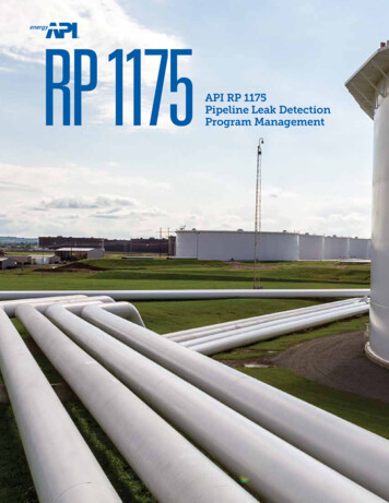
Detecting leaks using infrared cameras functions by usingvideo cameras that are fitted with a special filter thathighlights a selected spectrum of infrared wavelengths.Certain hydrocarbons absorb infrared radiation from thisspectrum and leaks are detected as a visual indicationsimilar to smoke in the video image.Figure 3: Causes of Pipeline LeaksLeak Detection MethodsWhat are our options when it comes to monitoringpipelines for leaks? Leak detection systems can becategorized into (2) major types; continuous and noncontinuous systems. The non-continuous systemsinclude: Inspection by helicopter, smart pigging, and eventracking dogs.Figure 5: Video Image of Gas LeakFigure 4: Leak Detection MethodsContinuous systems can in turn be divided into externaland internal based systems. External systems include:fiber optic cable, acoustic systems, semi-permeable sensorhoses and video monitoring. Internal systems include:pressure point analysis, Mass balance method, Statisticalsystems, Real Time Transient Model (RTTM) basedsystems and Extended RTTM. In practice, noncontinuous systems are often used in conjunction withcontinuous systems.Now let's take a look at how each individual systemfunctions. As we saw in the overview of leak detectionmethods, inspection by helicopter is one option fordetecting leaks. The helicopter flies along the pipeline,looking to detect any outflowing gas. Three commonmethods when detecting leaks by helicopter includedetection using Laser, Infrared cameras and "leaksniffers". When using lasers for leak detection, a laser isset to the absorption wavelength of the medium to bedetected. When the laser hits the medium, a part of thelaser energy is absorbed. The amount of energy absorbedfrom the laser is measured to arrive at the amount ofleaked medium.Leak sniffers draw in air samples to evaluate in ananalyzing unit to directly measure the concentration of theleaked medium. To do this, the helicopter must fly lowenough to pass through the gas cloud made by a leak. Theanalyzing unit then indicates whether gas is present and inwhat concentration. Helicopters are a good option todetect small gas leaks when the pipeline route is suitablefor accurate flight routes; however the accuracy alsodepends on the weather conditions. Poor weatherconditions mean that the leaking gas can drift and insevere cases the helicopters cannot even fly during suchextreme weather.Pipeline pigs are utilized for a variety of tasks in pipelineintegrity management. This includes cleaning thepipelines, separating product batches, as well as gaugingpipeline condition. It can help gain valuable informationabout corrosion, cracks, wall thickness as well as existingleaks in pipelines. In this case, we use the term smartpigging. To perform pigging, a pig is inserted into thepipeline using a pig launcher. The pig advances throughthe pipeline, propelled by the medium and gathers dataalong the way. A receiver is used to guide the pig out ofthe pipeline in order to subsequently analyze the collecteddata. Various techniques are used to collect pipelineinformation using smart pigs; two of the most commonare the magnetic flux leakage method and the ultrasonicprinciple.
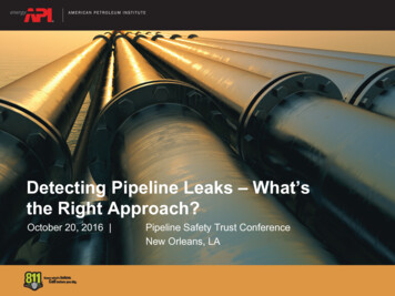
With the magnetic flux leakage method, a strongpermanent magnet is used to magnetize the pipeline. Anychanges to the wall of the pipe, such as corrosion, changethe magnetic flux lines which are then recorded bysensing probes attached to the pig. Following pigging,the recorded signals are evaluated based on referencesignals to detect any defects or abnormalities in the pipewall.When it comes to the method based on the ultrasonicprinciple, the pig transmits ultrasonic pulses into thepipeline wall and receives their reflected signals. Thesignals are reflected by both the inner and outer pipe wallsand based on the running speed of the pig; the thicknessof the pipe wall can be derived.By using smart pigs, existing leaks can be detected aswell as any damage to the pipeline which could result inleaks. Prior to commissioning pipelines they are oftenpigged and the results used as the baseline for furtherinspections. This is called zero or baseline pigging. It’simportant to ensure that the pipeline is piggable in thefirst place. This means that you must be certain that thereare no obstacles in the pipeline such as restrictions orfittings making the passage too narrow and that there arepig launchers and receivers to capture the pig. Inaddition, the speed of the pig must be kept between 3 – 15feet per second to obtain accurate results.Another non-continuous solution for monitoring leaks isthe use of tracking dogs. These dogs are specially trainedto recognize the odor of certain compounds which areinjected into the pipeline to be inspected. The pipeline isthen operated as usual and the dog is led along the rightof-way path, sniffing for the compound. The use oftracking dogs usually only takes place with short pipelinesor segments of pipeline. It is also a good method when itis not possible to accurately localize the leak using othermethods and then the dogs can be used to further narrowdown the leak site. However, it is difficult to certify atracking dog as a leak detection system within theframework of API or TRFL, for example.The use of fiber optic cables for the continuous externalmonitoring of leaks is based on physical changes thatoccur at the leak site. One of those physical changes is atypical change in temperature profile. To detect suchchanges, the fiber optic cable is placed along the pipeline.A laser then emits pulses that are reflected by moleculesin the fiber optic cable. The reflected laser pulsemagnitude gives insight as to the temperature at the placewhere the photon hits the molecule. By adding thesereflections, a temperature profile can be made and it isthen possible to detect the characteristic change intemperature that occurs at the leak site.Figure 6: Fiber Optic Leak DetectionMonitoring pipelines with fiber optic cables is a goodoption for accurately localizing leaks. However, use ofthis method is only possible up to limited lengths ofpipeline and many reflections are required to plot a usefultemperature profile. When installing the cable it is alsonecessary to pay attention to the medium to be monitored.If it is a gas to be monitored, the cable should be installedabove the pipeline as gas normally rises. When it comesto liquids, it makes sense to install the cable below thepipeline.Detecting leaks using acoustic signals is possible becausean acoustic signal is created when gases or liquids flowthrough a crack or hole in the pipeline. Acoustic sensorsare installed outside of the pipeline to detect leaks bymeasuring the noise levels at multiple sites along thepipeline. This information is used to create a noise profileof the pipeline. Deviations from the baseline noise profilethat is created results in the leak alarm. Acoustic sensorscan be mounted directly to the pipeline or coupled to thepipe wall using steel rods for underground pipelines. Tomonitor longer pipelines, a large number of acousticsensors are needed. Small leaks whose acoustic signal issmall and only differ slightly from the background noisecannot be detected as otherwise there would be manyfalse alarms.Figure 7: Acoustic Leak DetectionDetecting gas leaks using infrared is made possiblethrough video cameras featuring a special filter which issensitive to a selected spectrum of infrared wavelengths.Certain hydrocarbons absorb infrared radiation from thisspectrum. This makes it possible to detect the leaks as animage of smoke on the video display. Liquid leaks canalso be detected using infrared cameras as the thermal
conductivity in wet ground is different than in dry ground.In this case, you get a different temperature pattern abovethe leak position. Video monitoring of pipelines isdesigned for short distances. It is thus an interestingoption in critical areas such as on company premises orfor high consequence areas. For its use as a continuousleak detection method, however, it’s important to notewhether the leak detection occurs automatically orwhether monitoring by personnel is necessary.When using sensor hoses, a semi-permeable hose isinstalled along the pipeline. In the event of a leak, themedium comes out of the pipeline and into the hose. In atimed cycle, a test gas is injected into the hose at thebeginning of the pipeline. Then the contents of the hoseare pumped to the end of the pipeline. There is ananalyzing unit at the end which then tests the hosecontents for the presence of hydrocarbons. The run timeof the test gas injected at the inlet indicates the total runtime of the pipeline. As the total run time is known, thedifference between the arrival of the medium out of thepipeline and that of the test gas can be used to derive theleak site. Due to the material-specific properties of thehose, the use of sensor hoses usually only takes place inshort pipelines. The analyzing units can detect very smallvolumes of substances meaning even the smallest of leakscan be detected. Just as with fiber optic cables, wheninstalling the sensor hoses pay attention to the positioningof the hoses above or below the pipeline. Extended-RTTM (E-RTTM) based systemsPressure point analysis is based on the evaluation ofpressure drop or the pressure profile measured atindividual points. As a spontaneous leak brings up acharacteristic change in the pressure drop, you can checkwhether the measured pressure drop, DP within a timeperiod DT exceeds set thresholds. In addition to an upperthreshold, a lower threshold for the pressure is alsodetermined and if either one of these events occurs; thesystem triggers a leak alarm.Another type of internal leak detection system is based onAntoine Lavoisier's conservation of mass principle.According to this principle, mass in a closed systemremains constant and is not changed by processes withinthe system. If the pipeline is considered to be a closedsystem and you compare the mass flow at the inlet and theoutlet, the difference in a leak-free case should alwaysequal zero. If, however, a leak occurs, the system hasbeen opened and mass escapes. This results in a decreasein the measured mass flow at the outlet and an increase inthe mass flow at the inlet.Figure 9: Mass / Volume BalanceFigure 8: Sensor Hose Leak DetectionBefore we look at the individual methods of internalcontinuous leak detection let's first take a look at the basicfunctioning of these systems. When there is a leak thepressure and flow patterns in the pipeline change. Thesechanges are recorded by the instrumentation and theSCADA system transmits them to the control room. Theleak detection system then calculates whether there is aleak in the pipeline and the operator is informed at theOperator Station of the current status. Continuousinternal systems are based on the following principles: Pressure point analysisMass or volume balance methodsStatistical systemsReal Time Transient Model (RTTM) based systemsThe problem with this type of leak detection is that it doesnot take into account dynamic changes in the contents ofthe pipe, often referred to as line pack. This can happen,for example, when a gas pipeline produces more productthan is currently being consumed and the pipeline packs,serving as a large tank or cache. This type of leakdetection is thus also known as uncompensated massbalance.Statistical leak detection systems subject a previouslydetermined variable to a statistical test. Commonstatistical variables include pressure change over time andthe result of a mass balancing. The so-called hypothesistest is widely used here. With this test, two hypotheses areprepared, namely: Hypothesis H0: No leakHypothesis H1: Leak
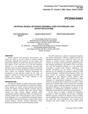
The system checks whether there is enough data for thestatistical variable to be a plausible part of the leakhypothesis and if it is, sends out an alarm.pipeline geometry and the properties of the product beingtransported the leak detection system calculates the actualchange in pipe contents or line pack. This is subtractedfrom the difference between the measured flow values F0at the inlet and FL at the outlet and results with thecurrent, compensated leak rate of the system.Figure 10: Statistical AnalysisReal Time Transient Model or RTTM systems cancompensate for dynamic changes. To do this, they makeuse of basic physical laws which the pipeline must obey: The conservation of mass principle, which includesthe density ρ, the time t, the flow velocity v and thepipeline location coordinates sThe conservation of momentum principle, whichincludes the flow velocity v, the time t, the pressureP, the pipeline location coordinates s, and thepipeline friction fsThe conservation of energy principle, which includesthe enthalpy h, the time t, the density ρ, the pressureP, and the specific loss performance LThese physical principles precisely describe the stationaryand transient behavior of the flow in the pipeline. Usingthese equations flow, pressure, temperature and densitycan be calculated and integrated in real time for eachpoint along the pipeline. These trends are also known ashydraulic profiles and accurately predict the trueperformance along the entire pipeline.Figure 11: Real Time Transient ModelBut how do we actually detect leaks? To answer thatquestion, let's take a closer look at the individualmeasurements. We also talk about RTTM-compensatedmass balancing. At the inlet the pressure P0 and thetemperature t0 are measured and at the outlet the pressurePL and the temperature TL are measured. Using thesemeasurements along with detailed knowledge of theFigure 12: Compensated Mass BalanceE-RTTM systems use the same principle as RTTMsystems. The pressure P0 and the temperature T0 aremeasured at the inlet and the pressure PL and thetemperature TL are measured at the outlet. Using thesemeasurements as boundary conditions the leak detectionsystem calculates using the laws of physics, expectedflow rates at the inlet and outlet. These expected valuesare then compared to the measured flow values F0 at theinlet and FL at the outlet. Subtracting the expected frommeasured values we then obtain the so-called residuals: X measured flow at the inlet – calculated flow atthe inletY measured flow at the outlet – calculated flow atthe outletIn a leak-free situation, both X and Y should equal 0. Inthe event of a leak, we see deviations where residual X 0 and residual Y 0.Figure 13: Residual shift due to leakIn order to avoid false alarms, E-RTTM systems also useleak pattern recognition. The system uses the residuals xand y as decision values and a leak situation is not theimmediate result of a deviation. Let's take a look atresidual x. Leak pattern detection accesses an expandabledatabase of different leak signatures and can thusdifferentiate between accidental interference (such as
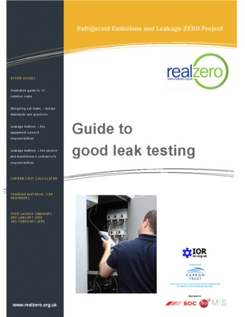
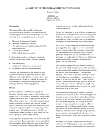
instrument drift) and leaks. Thanks to this special type ofsignal evaluation, small leaks are reliably detected andfalse alarms avoided.Figure 14: Pattern RecognitionNow that we know how the different internal leakdetection systems function, let's take a look at theircapabilities. Pressure point analysis shows a typicalminimum detectable leak rate starting at 5% of nominalpipeline flow rate. Detection time for liquid pipelines isshort, for gas pipelines it is long and only spontaneouslyoccurring leaks can be detected. The frequency of falsealarms is relatively high. With additional pressure gauges,high accuracy when it comes to localizing leaks ispossible, depending on the sensor sampling rate.Leak LocalizationWhen leaks occur in pipelines, it is not enough to knowthat a leak has occurred; you must also know where it islocated. There are several methods that can be used tolocalize the leak. Internal leak detection systems include: Gradient Intersection MethodWave Propagation MethodExtended Wave Propagation MethodThese methods can be combined to improve accuracy andto ensure that it is actually possible to localize the leak.Let's go into some detail on these methods to becomefamiliar with the advantages and limitations of eachmethod.Figure 16: Gradient Intersect MethodFigure 15: Typical Performance of LDS’sMass balance methods can typically detect leaks startingat a 1% leak rate. The time needed to detect leaks forboth liquids and gases is longer but creeping leaks canalso be detected. The frequency of false alarms is high inthis case as well, especially with transient pipelineoperation.Statistical methods generally detect leaks starting at a0.5% leak rate but the detection times are longer. Bothspontaneous and creeping leaks are detected and thefrequency of false alarms is low.RTTM-based systems detect both spontaneous andcreeping leaks quickly with a typical minimum leak ratestarting at 1%. The frequency of false alarms is average.E-RTTM systems can detect leaks in liquid pipelines veryquickly and in gas pipelines quickly starting typically at a0.5% leak rate. Spontaneous and creeping leaks aredetected and accuracy is high, as with RTTM-basedsystems. The frequency of false alarms is reduced or eveneliminated with the use of pattern recognition.The Gradient Intersection Method uses the pressureprofile along the pipeline to localize the leak. Ideally, thepressure drop is linear (in a horizontal pipeline withoutelevation changes). If a leak occurs, the flow before theleak site increases and decreases after. This results in anincrease in the pressure drop before the leak anddecreases after the leak, whereby we obtain two lines withdifferent slopes for the pressure profile. If you then followthe lines to the intersection, the leak site can bedetermined. The advantages of this method are thatspontaneous and creeping leaks can be localized and thatthe accuracy is good in stationary operation. Oneweakness of this method is that the accuracy depends onthe total length of the pipeline and that localizingaccuracy is not good in transient operation. In addition,with non-model-based systems you must take intoaccount any changes in the height, cross-section and pipefriction along the pipeline because the pressure drop isthen nonlinear due to these physical attributes of thepipeline and not from a leak.The Wave Propagation Method uses the sound velocity ofthe medium in the pipeline. Spontaneously occurringleaks create a negative pressure wave which propagates inboth directions of the pipeline at the speed of sound.Pressure gauges at the inlet and outlet record thesepressure waves and we obtain the point in time at whichthe pressure wave reached the sensors.
efficiency analysis, for example. The efficiency of apipeline decreases over time. Residues and depositsconstrict the cross-section, pipe friction increases andwith that the resistance of the pipeline against which thepump must work. A modern leak detection system canmonitor the efficiency status of the pipeline and help theuser operate his pipeline in an energy-saving, economicway, by indicating the current efficiency.Figure 17: Wave Propagation MethodThe differential time of arrival of the pressure wave cannow be obtained from these points in time. If the pressurewave arrives at both sensors at the same time that wouldmean that the leak was in the middle of the pipeline as thewave propagates in both directions at the speed of soundof the media, and if we assume a uniform density travelsat the same speed in both directions. The WavePropagation Method boasts good accuracy duringstationary and transient operation as long as operationalpressure waves are compensated for. The method can beused during pumping and during pauses in pumping.Creeping leaks and spontaneous leaks that are not largeenough cannot be detected with this method as thenegative pressure wave in these cases are not largeenough. In addition, the pressure gauges must samplequickly in order to measure the point in time of thepressure wave as accurately as possible.Figure 19: Efficiency AnalysisIn addition, model-supported systems with the help ofdensity profiles can portray an exact calculation of thecontents of the pipeline. This can be used, for example, tofinancially evaluate the amount of product currentlystored in the pipeline. This can be of great benefit,especially when it comes to long transport pipelines.Operator training is another added function. Simulated orrecorded field data can saved and replayed to be used totrain the operator directly at the HMI.In the case of theft, even the smallest leaks must bedetected. This requires a particularly high sensitivity suchas that offered by state-of-the-art leak detection systems.Figure 18: Expanded Wave PropagationTo attain better accuracy the Wave Propagation Methodcan be expanded by adding more pressure gauges. Nowwhen a leak occurs, we obtain additional points in time atwhich the pressure wave reaches the sensors. By nowtaking into account the sensor sampling time and theactual fluid density / sound velocity profile the exact pointin time at which the pressure wave reached the sensorscan be narrowed down even further.Additional FunctionalityIn addition to leak detection and localizing, leak detectionsystems can also take on other functions. One of these isIt is also possible for the leak detection system to analyzethe hydraulic profiles. In this way, taking into account theelevation profile of the pipeline, it can illustrate thepressure profile and in the case of over or under pressure,e.g. undershooting the vapor pressure of the medium, setoff an alarm indicating a ‘slack’ line condition.In the case of multi-product pipelines, it is interesting toknow what product is flowing through the pipeline at anygiven time. Using the leak detection system you canperform batch tracking. Here, the positions of theproducts and mixing zones within the pipeline aretracked. Batch scheduling allows arrival times andcapacities to be planned. Deliveries to individual tanksand buyers can also be scheduled. It is also possible toreduce the waste created by the mixing of products in thepipeline.
Figure 20: Multi-Product Batch TrackingSummaryPipelines and thus also leak detection systems can befound in a wide variety of areas for various products.Accordingly, the challenges that the leak detection systemfaces vary depending on the application.At the end of the day, the question is which leak detectionsystem is the right one? There is no one right leakdetection system. The selection must always be madewhile taking int
leak detection performance o The former API 1155, which contains performance criteria for leak detection systems, which has since been replaced by API 1130 o When evaluating individual leak detection systems, you American 49 CFR 195, which regulates the transport of hazardous liquids via pipeline and not decide based on a single specification.