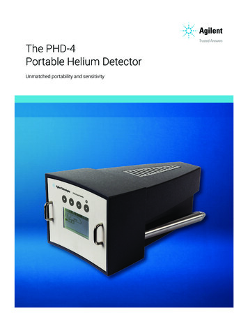
Transcription
The Helium Leak DetectorHelium Leak Detector Main ComponentsThe main components of a helium leak detector are:1. The analyzed, which enables to separate the tracer gas fromother gases inside leak detector. The most common type is amagnetic deflection type analyzer or a quadrupole type in theevent of testing multi-gasses. (As used in the refrigerationindustry). This devise allows to measure the partial pressure ofhelium. (See later in this document)2. A high vacuum pump, which is able to reduce the pressure in theanalyzer down into the 10-6 mbar pressure range. Most leak detectorstoday are equipped with either a turbo molecular pump, a moleculardragpump or a pump that includes the combination of both. These pumpsareideally suited for contra-flow operation, where the lighter gas molecules,suchas helium, can contra flow through the turbo back into the analyzer.Thiscontra flow principle provides the opportunity to start testing at high system pressures,which is ideal for finding larger leaks as common in industrial leak detection.3. A backing pump to support the turbo pump. This pump can bean oil sealed rotary vane pump. For hydrocarbon freeapplications, one can select a screw pump or a scroll pump.MatterAll elements helium, carbon, silicon and molecules (multiple element substances, such aswater, oil, and alcohol) consist of protons ( ), neutrons (neutral) and electrons (-)With helium being the most important for leak detection applications, we will focus on this gasand explain how the ionization process is takes place.Helium example, 2 electrons2 protons2 neutrons,
IonsIons are elements or molecules that havegained or lost electrons, resulting in a chargeimbalance. Once ionized, electric and / ormagnetic fields are used to control the speedand direction of the gas molecules.Example of helium ionized by e collisionA 90 degrees Deflection Magnetic AnalyzerAs an example for a magneticanalyzer, please look at ananalyzer with 900 deflection asshown on the left. In thisdrawing, we see all ionizedgases accelerated out of theionization chamber into amagnetic field.Only the selected gas (helium)will reach the target platethrough the different “lenses”and consequently reach the pre-amplifier (represented by the green dots).All light gases such a hydrogen will follow a smaller curvature (blue dots), while all heavymolecules will follow a larger curvature and can be collected on a different target plate to becollected for pressure measurements.Quadrupole AnalyzerA quadrupole mass spectrometer consists of an ionization chamber,an ion accelerator and a mass filter. The later consists of four parallelmetal rods. Each opposing rod pair is electrically connected and adirect current voltage is then superimposed on the RF voltage. Ions willtravel down the quadrupole between the rods and only ions of a certainmass-to-charge ratio will reach the detector. Other ions will collide withthe rods and will be filtered out.
Stand-alone Helium DetectorThis diagram shows allcomponents required to build astand-alone helium leak detector.This arrangement offers thecapability to firstly evacuate thepart to be tested to a vacuum levelcompatible with the critical foreline pressure of the turbo pump.Flow PrinciplesHelium can contra flow through the turbo pump back into the analyzer. Therefore, the inlet portof a leak detector can be connected to either the exhaust or an intermediate port of the highvacuum pump (mostly a turbo pump).By doing so, the leak detector system can start testing at higher test pressures. If the pressuredrops to levels that are comparable with the required analyzer pressure, the machine can thenswitch to a “direct” flow mode for higher sensitivities. In this situation, all molecules will reach theanalyzer directly.The advantage / disadvantages are shown with each flow mode below.
Industrial “Component” Helium Leak DetectorWhen a leak detector is used in alarge leak detection system withadditional pumping systems, theintegrator will be best served byreceiving a helium leak detectionmodule without valves andauxiliary parts. Most of the timesuch a module will include arecommended fore-pump to assurethe provided modulecharacteristics.Partial PressureWhat is Partial Pressure?Ambient air is composed of various gases. The pressure “created” by each individual gas iscalled partial pressure.Under normal ambient condition, we find 5 ppm of helium or 5 * 10-4%.Ambient air compositionThe table on the right shows thecomposition of ambient air by symbol, %by volume and PPM
Partial Pressure Influence in an ApplicationContainer A is filled with pure Oxygen at 5 bar.Container B is filled with pure Nitrogen at 11 barThe total pressure in container C is 16 is bar, being the sum of the partial pressure of oxygenand the partial pressures of nitrogen combined.Conclusion: the different molecular types do not affect each other in container C, but will hit thewalls as many times per second and with equal force when they are mixed. (Like they would ifthey were the only gas type present in the container).What is Helium? Helium is a standard element with a molecular weight of 4 amu (atomic mass units).Helium is available in small concentrations in the ambient air. This provides for lowhelium background “noise” in a leak detector and makes helium a very attractive gas forleak detection applications.Helium is readily available on a worldwide basis.Helium is not toxic.Helium is not flammable.Helium is an inert gas.Helium is available in cylinders of various sizes and it meets thehighest standards, as set for the most demanding medical applications. For helium leakdetection applications customers should use balloon gas with a accuracy of around99.99%.Helium Partial Pressure in AirTo calculate the partial pressure of helium in ambienthelium we simply multiply the air pressure in mbartimes the concentration of helium in ambient air. (5ppmor 5 *10-4%) Assuming ambient pressure at 1000 mbar,the partial pressure for helium is then calculated to be5 * 10-3 mbar.
“Hard” Vacuum Detection MethodsWhy Dynamic Leak Detection?Dynamic helium leak detection got its designation by the fact that leak measurement is obtainedin a system that is constantly pumped by a vacuum pumping system. The system includes ahelium mass spectrometer. This in contrast to a vacuum decay processes where the pumpsource is valved off to observe a pressure variation.The Units used in Helium Leak DetectionWhen discussing a leak or flow, the pressure and volume of gas displaced in a particular periodmust be included. As gas volume is the product of volume * pressure, the gas flow can beexpressed asError!The leak rate units used are: Normal.liter/hour, mbar.l/s, atm.cc/s, Pa.m3/s, SCCM, mm3/s.Measuring Total Leak Rate (Inside-Out)A part pressured at a defined pressure and aknown helium concentration is placed in avacuum chamber pumped by a leak detector orleak detector system.By using this test method, it is possible tomeasure the total outflow of helium from thepart in a calibrated way. (This technology doesnot allow to pin point the leak location(s).Measuring Total Leak Rate (Outside-IN)The part to be tested is evacuated by a vacuumpumping system. When the appropriate cross overpressure is reached, the leak detector is valved in.At the same time, the part is covered by anenclosure. Helium is admitted into the enclosureand if there is a leak(s), the helium will enter thepart. The detector is now able to measure the totalleak value (includes multiple leaks), if the heliumconcentration and pressure in the enclosure areknown.Also in this method, the location of the leaks will not be known.
Note:The leak reading will not be correct if the enclosure does not contain 100% of helium. (Theenclosure needs to be pre-evacuated to reach this objective).After removing the enclosure, the operator can spray helium using a spray probe to “pinpointing" the exact leak location(s).Accumulation MethodHelium Accumulation PrincipleHelium accumulation became a more and moreacceptable helium leak test technology that allows forquantitative measurements at a lower cost than a “hard”vacuum method. There is no need for a vacuum pump(s)or a costly vacuum chamber. In this technology helium gas or a gas mixture isapplied to one side of a containing wall. The increase of helium concentration (partialpressure) on the opposite wall in an enclosure isobserved over time.Helium Accumulation CalculationsError!Q Leak rate in mbar.l/secP Pressure in mbarC Helium concentration at the start of the testCo Helium concentration at the end of the testV Volume in literst Time in secondsBombing Method
Bombing or Backfilling PrincipleThe backpressure method is used when a part ishermetically sealed.In order to test such a component (electronicpackages, relays, transistors), the part is: Step 1. Placed inside a so-called bombingchamber, which is pressurized with heliumto a defined pressure level. This will allowthe helium to accumulate inside the part ifthere is a leak.The part will stay inside this bombing chamber for a fixed period.The part is removed from the bombing chamber and will be exposed to ambientconditions for an aeration process. (This is performed, so the helium can escape fromthe surface avoiding high background readings. (Flushing nitrogen gas over the part willaccelerate this process).Step 2. The part is placed inside a vacuum chamber that is connected to a helium leakdetector. Helium, which entered the part through a leak during the bombing cycle, cannow escape and produce a signal on the detector display panel.Based upon the bombing time, bombing pressure, aeration time and internal volume, acorrelation can be calculated between the true leak and the leak indicated by the leakdetector.Bombing Technology DetailsHowl-Mann EquationR Measured leak rate of tracer gas through the leak in atm.cc/sec.L Calculated leak rate in atm.cc/sec.PE Pressure of exposure in atmospheres (gauge pressure).Po Atmospheric pressure in atmospheres.
MAMt1t2 Molecular weight of air. Molecular weight of the tracer gas. Time of exposure to PE, in seconds. Dwell time between release of pressure and leak detection in seconds.V Internal volume of the device package cavity in cc.Indicated Leak versus Actual LeakBased on MIL STD 883 B the reject level for partsis defined using the Howl-Mann equation. Theresult is shown in the example on the right.The complete ratio range between actual andindicated leaks is displayed in the below graphusing the same specifications: Bombing at 10 atm (Abs),Internal volume of 0.1 cc,Bombing time of 5 hoursAeration time of 0.5 hours.It is interesting to see that for the same indicated leakthere are 2 actual leak readings! The reason is quitesimple.In one case, there is a large leak, so only a smallamount of helium at low pressure is left. This lowhelium pressure/concentration is producing a smallsignal for a large leak. In the other situation the heliumpressure and concentration are higher andconsequently it can produce the same signal for asmall leak. (See curve to the right)Spraying TechnologyOut-side-in TestingIn leak test applications, helium is admitted to oneside of a containing wall and is detected through aleak on the other side of that wall.In the following paragraph, the focus is on technique,where the pressure on the spraying side of the wall ishigher than the pressure on the detection side. Thisis called the “outside-in” test method.Helium behavior
Admitting or spraying helium is done by using a spray pistol, where the flow of helium can beadjusted to meet the requirements for detecting or pin-pointing a leak.A part can also be covered with a bag that can be filled with helium. In this case helium can beadmitted through a large nozzle.Helium handling and helium spray control are critical factors for fast, accurate leak detectionespecially for systems with:****Multiple leaksMultiple elastomersDifficult sealing conditionsHigh production throughputsBecause helium is a very small, light molecule, which disperses rapidly in the environment andpasses easily through any opening or crack, difficult test conditions and false leak indicationscan occur.When testing by the vacuum method, there are two specific methods:1. The "bag" method In this method, a general leaktest is performed. The part tobe tested is placed completelyor partially in a container.(Can be a plastic bag). The bag is filled with helium ata pressure thanatmospheric conditions.Using this technique, we obtain an overall indication of the system tightness.Using this technology will not allow the differentiation between a single leak or multiple leaks.Additionally, there is no indication of the leak location(s). The reading is of course affected bythe helium concentration created inside the container or bag! (When using a plastic bag, thehelium concentration will never be 100% and therefore, the leak detector will never provide acalibrated value of the actual leak rate!)
2. The "Pinpointing" methodIn this method, the operator canpinpoint the exact location of the leakby spraying a small flow of helium onselected locations. This techniquecan be applied from the beginning orin combination with the “bagmethod”. A calibrated reading canonly be obtained when 100% helium is present at the leak location.For both methods, understanding of helium behavior is necessary, as response time, clean uptime, and background issues created by helium contamination of the environment have animpact on the test procedure and the results.Issues with the Out-side in Method When admitting helium into a container, sealed bag, as discussed above, the helium willneed to be dispersed inside the enclosure and a uniform concentration must be built up.This concentration build-up will depend on the helium flow into the bag and on thevolume of the enclosure. For small volumes, a significant difference in concentrationbetween the various locations within the volume cannot be noticed, but in large spaces,a higher concentration at the top of the volume may be observed, as helium will rise.Leak testing in an environment without proper venting will cause an increase in ambienthelium concentration in the room. This can result in a high detector background sincehelium can permeate through elastomers (see permeation below). Further, helium canback stream into the vacuum system and leak detector through the exhaust of the forepump due to the contra flow effect, resulting in a higher helium background.In general:1. Use a controlled helium spraying technique to minimize helium in the area2. Using proper venting to remove spent helium from the work area3. Exhaust the fore pump of the leak detector outside the room, so helium cannot backstream into the detectorTips for Spraying TechnologyTo pinpoint leaks or to test smaller systems, just use a few bubbles per second, this; Helps minimize background heliumImproves instrument cleanup following gross leakImproves instrument sensitivityImproves instrument stabilityHelps avoid misidentification of leak locationIn windy environments consider: Testing from downstream of the system upstream
Using a wind barrier while fine testingIsolating nearby fittings with a barrier, such as a rubber glove while spraying the fitting undertest. It is also possible to isolating the fitting under test with a barrier and introducing heliuminside the barrierTo obtain correct readings: Displace air at the leak location with 100% heliumApply helium long enough to reach a full stable signal (see response time calculations seelater in this document)Have knowledge of the split flow ratio if a second pump is active on the vacuum system (seesplit flow operation for details)Helium gas is very light and rises quickly. For that reason, it can surprise an inexperiencedleak test technician looking for a leak at the bottom of a system. He can get a false leakindication signal from helium coming through a leak at the top of the system.Corrective action: Careful sprayingUse a minimum amount of helium (see helium flow below)Use protective shielding if necessaryAvoid draft and turbulenceStart at the top of a system or installation and work downAdjusting a spray probeTo pinpoint a leak, it is not necessary to use a large flow of helium. In fact, that might lead tomany of the difficulties as listed above. An appropriate flow is established by inserting the sprayprobe in a cup with water and adjusting the helium flow to obtain 2 to 5 bubbles per second. If a flow is too small, a leak can be passed over without a recognized response If a flow too large, it can result in false indications and long clean up times if a large leakis discoveredSniffing TechnologyInside Out or Sniffing TechnologyIn this technique, the part is pressurized withhelium or with a mixture of helium and air ornitrogen. A sniffer probe connected to a leakdetector is used to sample the heliumescaping through a leak.To obtain a general indication of a leak, thepart under test can be covered with a domeor just a simple plastic bag. By reducing the dead volume of the dome or bag to a minimum, thesignal will increase more rapidly. (It is important that the cover or bag does not touch any part ofthe item to be tested that might be subject to possible leaks). The sniffer probe must be insertedinto the bag or dome at the highest point to follow the concentration increase more quickly andaccurately.
In a next step, the operator can remove the cover and manually scan the surface of the part withthe sniffer probe. This will allow to "pin-point" the leak the location(s).Helium Background in SniffingSensitivity for helium sniffing is limited because of the 5 ppm of helium in ambient air. With thisin mind, the smallest leak that most manufacturers of helium leak detectors advertise is 1 * 10-7mbar.l/s. This number is not very practical for industrial applications, as it requires working in anon-drafty environment and all helium escaping through a leak needs to be captured by the leakdetector. For this reason, the advisable specification for industrial applications is set at 5 * 10-6mbar.l/s.Note:A sniffer probe must be seen as a defined leak connected to the helium leak detector. Assumingthis leak to have a value of 1 * 10-2 mbar.l/s (This value shows up if we would spay helium at100% concentration at the probe inlet). The ambient reading on the calibrated helium leakdetector may be measured as:1 * 10-2 mbar * (5 * 10-4)% helium concentration 5 * 10-8 mbar.l/s. (Please be advised this valueis never the value of the leak that is beingmeasured!)Sniffer Probe TechnologyThe signal strength that can be obtainedusing a sniffer probe depends on two majorelements: Probe distance to the leak.Probe speed when passing a leaklocation. (See illustrations below).Sniffing Technology DetailsRegarding sniffing technology, the following additional information might be important for theuser:
The operator needs to find all individual leaks and to combine their values to determine thetotal leak specification.If there is no true tracer gas leak infront of the probe, the test gasconcentration in the suction gas flowequals the ambient concentration (Co).A stable and clean environment isnecessary for operations, where stablehigh sensitivities are required.Probe flow conditions have a majoreffect on the sniffing capabilities andeven the slightest change in probe flowconditions (for instance caused by contamination) has an impact on the system accuracyand performance.The sniffer probe can be used to perform quantitative measurements is by applyingaccumulation technology. (See accumulation technology).Where Helium Detection Methods are usedSpray Probe Vacuum systemsTesting objects able of withstanding one atmosphere pressure differentialSniffer Probe Systems that can be pressurized (e.g. gas delivery lines and pressure vessels). Systems with poor vacuum conductance or containing high vapor pressure materials(e.g. water cooling lines)Outside-in Testing / Inside-out Testing Components capable of withstanding 1 bar or 14.7 psi pressure differentialComponents able to withstand minimal pressure differential using specialized pumpingtechnologyBombing Small sealed devices (e.g. ICs)Accumulation Sealed components not capable of withstanding one atmosphere pressure differentialComponents or systems too large for inside-out testing
The Helium Leak Detector Helium Leak Detector Main Components The main components of a helium leak detector are: 1. The analyzed, which enables to separate the tracer gas from other gases inside leak detector. The most common type is a magnetic deflection type analyzer or a quadrupole type in the event of testing multi-gasses.