Transcription
INSTALLATIONMANUALPin Foundations, Inc.Gig Harbor, WashingtonToll Free: 866-255-9478 / Main Office: 253-858-8809www.pinfoundations.com or www.diamondpiers.com
2016 by Pin Foundations, Inc. All rights reserved.Form # INST1211, Rev. Jan 2016.Diamond Pier Foundation Systems are covered by U.S. Patents 5,039,256; 6,910,832; 7,326,003; andpatents pending.Diamond Pier is a U.S. registered trademark of Pin Foundations, Inc.The latest version of this Installation Manual is available on our website, www.diamondpiers.com, or bycalling us at 866-255-9478 (Toll Free) or 253-858-8809 (Main Office).Other documents and publications referenced in this manual are listed below and available atwww.diamondpiers.com.National Evaluations“Diamond Pier DP-50 Precast Concrete Pier Foundation Assembly,” ICC-ES Evaluation Report No.ESR-1895.State Evaluations“Diamond Pier DP-50 Precast Concrete Pier Foundation Assembly,” Wisconsin Building ProductEvaluation, Code Approval No. 201008-O, July 26, 2011.Test Reports“Precast Concrete Pier Foundation Assembly Test Report; In Accordance with ICC-ES AC336,”Professional Service Industries, Inc., PSI Report No. 704-25035-1, November 28, 2006.“Cross Pin Group Foundation Load Test Report,” Earth Engineers, Inc., EEI Report No. 07-020-8,January 21, 2013.Observational Evidence“Diamond Pier National Performance Submittals,” 2005.“Diamond Pier Frost Performance Report, Zone II, Minnesota Soils,” 2010.“Diamond Pier Observational Evidence, Forest Lake, Minnesota,” May 2011.Building Code Compliance Documents“Code Compliance Information for Diamond Pier Foundations in the State of Minnesota,” PinFoundations, Inc., September 2013.
CONTENTSINTRODUCTION . 4Soils . 4Pin Pile Technology . 4Diamond Pier Foundation System . 4CONDITIONS AND USES . 5Normal Soil Conditions . 5Supporting Soils . 5Residential Diamond Pier Load Chart. 6Use and Applications . 7Frost Heave . 7Heave Resistance . 7INSTALLATION INSTRUCTIONS . 8Preinstallation . 8Product Warranty . 8Inspect for Underground Obstacles . 8Locate Buried Utilities. 8Check Your Layout . 9Assemble Tools and Supplies . 10Installation . 10Identify and Mark Location . 10Set the Concrete Head . 10Drive in the Pins . 11Place Inspection Caps on Pins . 13Register Your Product Warranty . 13AUXILIARY PARTS AND EQUIPMENT . 14Post/Beam Brackets . 14Breaker Hammers and Driving Bits . 14FIELD INSPECTION . 15Pin Length . 15Pin Specifications . 15Pier Integrity . 15Allowable Capacity . 16Inspection Plugs. 16SPECIFICATIONS . 17References/Standards . 17Delivery/Storage and Handling . 17Pins . 17Connections/Posts/Beams . 17Site . 17Installation . 17TROUBLESHOOTING . 18Diamond Pier Installation Manual3
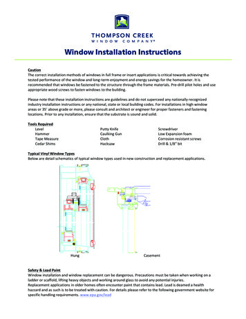
INTRODUCTIONSoilsPin Foundations, Inc. (PFI) has been designing and manufacturing foundations for over 25 years. Onething has always driven our thinking—the Earth is the actual foundation, and soils, in their naturalundisturbed state, have the strength and structure to do the job.Man-made foundations have two basic functions: to transfer loads properly into the Earth’s soil structureand to provide a connection to the built structure above. There are two general types of man-madefoundations: deep vertical pilings (banged in) and shallow spread footings (dug in and buried). Pilingskeep the Earth’s existing soil strength and structure intact, and are easy to install if they do not need togo too deep. Footings spread loads more widely, but the digging breaks apart the soil, weakening it andblocking or exaggerating water flow.Pin Pile TechnologyPin pile technology combines the best features of both types of man-made foundations. By groupingshort stiff piles (bearing pins), which can easily be driven into intact penetrable soils, and setting them atangles to work more like a shallow footing, a sound foundation can be constructed that requires noexcavation. The pin pile group simulates nature’s design, resembling the roots of a tree providingbearing, uplift and lateral capacity. In recent decades, grouped pin piling has become a reliable technology for complex, heavy-duty commercial applications, performing a superior job of transferring loadsto intact undisturbed soils.Diamond Pier Foundation SystemPFI’s innovation is to bring pin pile technology into common use with a superior connector—the Diamond Pierconcrete head. This high-strength, precast component isa driving guide, a pin piling lock, and a structural connection all in one. As a driving guide, the pier maintainsthe pin angles so that their capacity is definable andconsistent. As a lock, the pier is designed to increase itsgrip on the pin cluster when loaded up, down, or sideways—getting stronger and tighter as loads increase.And as a connection, an embedded anchor bolt andprecast, post-matching shape make it a simple andproportional complement to its supported structure.AnchorboltConcretepier headInspectioncapBearingpinInspectionplugThis composite pier combined with the bearing pin groupFigure 1. Diamond Pierforms the Diamond Pier system—a hybrid of familiarFoundation Componentsconcrete and steel materials. It provides a solid, stable,economical foundation that both captures and preserves the supporting strength and natural functions ofthe Earth’s soil it's engaged in and, in turn, solidly and simply connects to and protects the permanentstructures above.This manual provides information and instructions for installing Diamond Pier foundations in residentialapplications in Normal Soil Conditions (see next section).4Diamond Pier Installation Manual
CONDITIONS AND USESNormal Soil ConditionsDiamond Pier foundations sold through retail outlets are designed for projects that are founded in normalsound soils. Normal soils are typical in most residential neighborhoods throughout the United States andare defined in the International Residential Code (IRC) Table R401.4.1. Presumptive Load-BearingValues of Foundation Materials.For residential applications the two most common prescriptive bearing soil types relied upon in the IRCtable, and in most local codes, are 2000 psf sands/gravels and 1500 psf silts/clays. Diamond Pierfoundations sold through retail outlets must be founded in soils with a minimum 1500 psf bearingstrength. Supporting soils that do not meet the presumptive bearing strength defined in the applicablecode for your area will not provide expected foundation capacity, and their bearing capacity may need tobe determined by a soils investigation. Ask your local code official for soil information regarding yoursite. Additional soils information may also be available at the U.S. Geological Soils Survey websitemanaged by the U.S. Department of Agriculture—see http://websoilsurvey.sc.egov.usda.gov/.Supporting SoilsSome soils may not be appropriate for supporting Diamond Pier foundations. Some examples includesoils that are weaker than 1500 psf, soils that are highly expansive, shifting or sliding soils, soils onslopes greater than 2:1 (27 degrees), contaminated soils, or soils where traditional concrete piers,accepted by local codes, are unable to provide adequate bearing to support the loads of the project or toprotect the structure from the negative effects of frost heave. Where unsound soils exist, a registereddesign professional may be required to review the project.Soils can also be weakened when they retain standing water or are improperly drained, and in certaintypes of soil this can also cause heave problems. A site depression with standing water or the potentialfor water to pond, pool, or saturate the soil may be an indication that the soil is not sound. Downspoutsthat discharge at or near a foundation may also cause soil problems, and setting the Diamond Pierfoundation system adjacent to or near drainage ditches, creeks, or ponds should be consideredcarefully. Soils adjacent to existing foundations may also have been improperly or loosely backfilled,which may cause poor drainage or poor soil conditions. Check your local code for drainage requirementsin and around foundations.Please contact PFI if you have any questions regarding your project or soil conditions, and/or the properuse of the Diamond Pier product or "Residential Diamond Pier Load Chart," provided in Table 1.WARNING: You must check for underground utilities and follow the instructions describedunder the “Locate Buried Utilities” subsection (page 8) before Diamond Pierfoundations can be installed.Diamond Pier Installation Manual5
Residential Diamond Pier Load ChartTable 1. Residential Diamond Pier Load ChartEquivalency to a traditional concrete pier is indicated by Base Area Comparison and Frost Zone Rating.U.S. Patents:IRC Prescriptive Bearing ESR-18955,039,2566,910,8327,326,003DP-50 36”DP-50 42”DP-50 50”DP-75 50”DP-75 63”3600#3600#3600#5150#5850#Bearing in 1500 psf Silts/Clays12700#2700#2700#3870#4400#Equivalent Bearing Area1.8 sf1.8 sf1.8 sf2.58 sf2.93 sfBase Area Comparison18” cylinder18” cylinder18” cylinder21” cylinder23” 0”Model & Pin Length Bearing in 2000 psf Sands/GravelsFrost Zone Rating1Notes:1. Values applicable in properly drained, normal sound soils with a minimum 1500 psf bearingcapacity. See IRC Table R401.4.1 for complete bearing soils listing and Table notes.2. For simple structures only. No asymmetrical, rotational, overturning, or dynamic loads.3. All capacities use four pins of the specified length per foundation. Length includes that portionembedded within the foundation head.4. DP-50 uses defined in paragraph 2.0 of ESR-1895 and per blue-bordered box above are limitedto residential decks, covered decks, stairways, and walkways. For DP-50 uses beyond thesetypes of projects, and for DP-75 applications, refer to Cross Pin Group Foundation Load TestReport (EEI Report No. 07-020-8). See Note 1 for applicable soils.5. The DP-50 comes with a 1/2” diameter embedded galvanized anchor bolt. The DP-75 comes witha 5/8” diameter embedded galvanized anchor bolt.6. The Diamond Pier system is a shallow bearing technology that does not require “refusal” or“friction” resistance, or the professional installation monitoring or special inspection typicallyassociated with conventional vertical or battered piling.7. This load chart is intended for applications supported by columns, posts, and beams loaded up tobut not exceeding the stated capacities. For applications where the load requirements exceed thecapacities defined in this chart, a site-specific capacity review is required. Project soils data andstructural loading information must be provided. Refer to “Commercial and Special-Order ProjectServices” and “Diamond Pier Foundations – Use and Applications”; both documents are availableat www.diamondpiers.com.6Diamond Pier Installation Manual
Use and ApplicationsDiamond Pier models DP-50 and DP-75 sold through retail stores are used to support columns, posts,and beams that are limited to the capacities of the “Residential Diamond Pier Load Chart” shown inTable 1. The load chart shows that Diamond Pier foundations provide equal or better performance whencompared to traditional concrete foundations claimed as equivalent.In the residential load chart, “base area comparison” and “frost zone rating” values are given. These twovalues define the size of the traditional concrete pier foundation that a given Diamond Pier foundation isequivalent to in bearing capacity and frost heave resistance. For example, a DP-50 with 50" bearing pinsshows a base area comparison of 18” and a frost zone rating of 48”. This compares with a traditional 18”round, 48” deep poured concrete foundation. For more information, please refer to the “Diamond PierFoundations – Use and Applications” document at www.diamondpiers.com.Frost HeaveFrost is not an unusual or unsound soil condition unless the site has a history of locally acceptedconventional foundations failing due to frost heave or freeze/thaw cycling. In frost zones, a properlydrained, sound soil will freeze solid and hold its foundations tight. In heaving areas, water sources, therate of temperature drop, and certain soil grain sizes can combine to cause pressures on foundations inall directions. The most important of these three factors is the presence of water in the soil, and thismakes proper drainage a must—for all types of foundations.Heave ResistanceMost traditional concrete foundations in frost zones rely on depth and gross weight as protectionsagainst frost heave. They use significant volumes of site-poured concrete, which has the potential formany field condition variables and inconsistent mix designs, and their installation requires considerableexcavation, which weakens the existing soil structure, invites water problems, and leaves substantialamounts of soil to be removed from a site.Diamond Pier systems resist heave pressures and are often used in areas requiring frost protection.Rather than reaching a specific vertical depth or gross weight, Diamond Pier systems resist heavepressures with their wide-spreading pin pile groups. Embedded in the intact soil structure, the pins areprevented from changing angle under load by the concrete head, creating a stable foundation for bothbearing and uplift forces. Because of the unique design of the Diamond Pier head, the pins are also freeto move along their axes without compromising the position of the pier or its lock on the pin cluster. Thisfeature allows the Diamond Pier foundation to absorb soil strains caused by frost heave or expansiveconditions without losing alignment or transferring these strains to the supported structure.When assessing projects in extreme frost areas, be aware of sites where traditional concrete footings—48” to 60” deep—have failed to resist frost heave, requiring larger, deeper concrete piers. Project sitesthat require concrete footings deeper than 60” to resist frost heave exceed the definition of normal soilconditions and the limits of the "Residential Diamond Pier Load Chart."Diamond Pier Installation Manual7
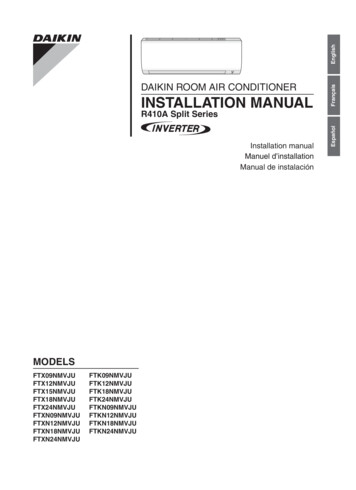
INSTALLATION INSTRUCTIONSThese instructions only cover the installation of Diamond Pier foundations in residential applicationswhere normal soil conditions exist and the “Residential Diamond Pier Load Chart” (Table 1) isreferenced (see discussion of “Normal Soil Conditions” on page 5 and “Residential Diamond Pier LoadChart” on page 6).Please also view the Installation Video provided on our website, www.diamondpiers.com.PreinstallationProduct WarrantyRegister your product warranty. Go to www.diamondpiers.com to view warranty information and download the Limited Lifetime Warranty Application Form.Inspect for Underground ObstaclesThe same obstacles that conventional foundation systems encounter, such as rocks, tree roots, underground utility lines, and other buried objects, can also obstruct the Diamond Pier system. Refer to the“Encountering Obstructions” subsection (page 12) for instructions on handling buried obstacles. If anobstacle is encountered that cannot be passed using the breaker hammer while driving the pins and notcracking the pier head in the process, the pins can be removed and the concrete head rotated, allowingthe pins to penetrate the soil in a different location.Locate Buried UtilitiesWARNING: Do not install Diamond Pier foundations before all underground utilities havebeen located, marked, and de-energized.All underground utility lines must be located and properly marked by your local official utility locatingservice, and all privately run lines must also be identified and located by the proper authority. If there areany electrical lines in the area, de-energize the power source prior to installing the Diamond Pier foundations. Never allow bodily contact with uninsulated portions of the automatic breaker hammer. Wearproperly rated rubber-insulated gloves and boots. In, addition, if underground utilities are located on thesite, check with your local utility locating service to confirm required safety zones. You must ensure thatthe horizontal pin distance for your foundation will have adequate horizontal clearance to be well outsideall safety zones (see Figure 2 and Table 2 on next page).8Diamond Pier Installation Manual
DPSafetyZoneLimit PlaneUtilitySafety ZoneHorizontal PinDistanceBuriedUtilitiesFigure 2. Horizontal Pin DistanceAfter installation, horizontal distance of all pins must be well outside all safety zones.Table 2. Horizontal Pin Distance for All Diamond Pier ModelsMeasured from center of pier anchor bolt horizontally to vertical limit of pin end.Horizontal Pin Distance (inches)Pin Length(inches)When Pin Is at 90 degrees(Perpendicular to Limit Plane)When Pin Is at 45 degrees(Shortest Distance to Limit Plane)3620154224175029216338278451361267856Check Your LayoutTo meet the load bearing capacities shown in the “Residential Diamond Pier Load Chart” (Table 1, page6), Diamond Pier foundations must be spaced a minimum of 3 feet apart (from center of pier anchor boltto center of pier anchor bolt). If they are spaced less than 3 feet apart, the bearing capacity must bereduced by 13% for each closer-spaced pier. The piers must also be set back the correct horizontaldistance from existing foundations or other buried obstacles, as shown in Table 2. Tributary loads fromthe supported structure must be properly calculated, and the piers spaced accordingly, so that each pieris supporting only up to its designated allowable loads.Diamond Pier Installation Manual9
Assemble Tools and SuppliesInspect your Diamond Pier assemblies to ensure that no parts are flawed or have been damaged inshipping. Do not install a concrete pier if it is a structural crack with a fissure running internally into thepier (see "Pier Integrity" on page 15). Slight flaking or chipping is acceptable; a pier with surface flakingor chipping may be installed.Verify that you have the correct number of concrete pier heads with the corresponding number ofbearing pins (4 per pier), inspection caps (4 per pier), and inspection plugs (4 per pier), and that theanchor nuts thread properly on the pier anchor bolts.You will need to assemble the following tools and gear: Automatic driving hammer with 1-1/8” hex shaft driving bit (see "Breaker Hammers and DrivingBits," page 14)Square-edge shovelSledgehammerTorpedo levelTape measurePipe wrenchProper safety goggles, ear protection, insulated gloves, protective clothing, and bootsWe recommend a minimum two-person crew for installation.InstallationIdentify and Mark Location1. Locate where you would like the center of the pier anchor bolt to be.2. Mark the location by using reference points that will easily identify the center location of the piereven after top soil is removed. Tip: Set a string line centered on the anchor bolt approximately12-14” above the ground for a quick reference point and to maintain alignment.Set the Concrete Head1. Dig a tapered square hole the same size andshape as the bottom half of the concrete head (seeFigure 3). This creates a cradle to steady the pierfor leveling. Soils directly below the pier should beleft loose.2. Following safe lifting procedures, carefully lift theconcrete head and position it in the hole to itsmidpoint.* Ensure top is level and centered on youralignment.3. Replace some of the removed soils back aroundthe sides of the pier at grade, lightly tamping tomaintain level and alignment during pin driving.(See Notes under “Drive in the Pins” on page 11.)A few inches of small rounded pea gravel may beused around head if native soils are not available.Figure 3. Tapered Hole forConcrete Head*The pier may also be buried for aesthetic considerations, but access to the top of the pier needs to bemaintained. Concrete slabs, patios, and other products installed MUST NOT interfere with the DiamondPier System and the attached post/beam assembly. Expansion joints are commonly used to protect thesystem. Proper drainage must also be maintained.10Diamond Pier Installation Manual
Drive in the PinsWARNING: Verify locations of any buried utilities before driving pins (see “Locate BuriedUtilities,” page 8).1. Remove any dirt and debris from the pins andcheck that they will fit easily into the driving holesin the concrete heads. (If a cut or burr is restrictingthe fit, try the other end of the pin.)2. Install the inspection plugs in the ends of the pinsthat will go into the pier first.3. Slide the pins through opposing holes in the concrete head, making sure to support them so theirweight doesn’t roll the pier out of the hole or out ofalignment.4. Keeping the pin centered in the driving hole, carefully set pin 6” to 12” into the soil tapping with thesledgehammer (gripped just below the hammerFigure 4. Setting Pins andhead) until the pier is locked into a level positionLeveling Pier(see Figure 4). Impact the pin end squarely tominimize flaking of the concrete surface or deformation of the end of the pin (see Note 1).5. With the pin driving bit installed on the automatic hammer, and another crew member holding thepin, drive in opposing pins alternately in increments. Periodically check for alignment and level (a5-degree tolerance is allowed). Be sure to keep the weight of the auto-hammer from forcing thepin against the lower half of the driving hole and impacting the pier. Another crew membershould hold the pin centered in the driving hole (see Figure 5). This will also reduce pin vibrationand minimize concrete flaking.NOTE: Do not use the pin driving bit as a hammering tool or hammer against it with thesledgehammer. It is to be used with the automatic hammer only.6. Temporarily drive all pins down to within 6” fromthe top of the pier; this allows easier removal if anobstruction is encountered.7. Finish driving the pins with the automatic hammer(with pin driving bit), being careful not to damagethe precast pier or the upper ends of the pins andleaving approximately 3/4" of the pin protrudingfrom the top of the concrete.Note 1: Do not attempt to drive the pins all the waydown with just a sledgehammer; this may damage theends of the pins or crack the pier.Note 2: Do not drive a pin all the way down at once ifthis causes the pier to be pulled to one side. Continueto rotate around the pier, driving the pins in increments, until the growing strength in the pile group issufficient to allow final driving.Figure 5. Driving Pins withNote 3: Do not continue to hammer away at a pin thatAuto-hammer and Pin Driving Bitis bouncing, rattling, or scraping against an impassableobject. This may cause the pier to ride up the pin, push the pier to one side, or risk eccentricallystressing the pier with a pin that is out of line. It could also cause the pier to have a structural crack,which would require removal and replacement (see "Pier Integrity" on page 15). If encounteringdifficulties in the soil, see “Encountering Obstructions” on the next page.Diamond Pier Installation Manual11
Encountering ObstructionsIf a pin stops moving when being driven in, STOP driving the pin. Be sure the other pins are at leasthalf way in to stabilize the pier and ensure that the pier will remain in place before trying to drive theobstructed pin in any further. Attempt to drive the obstructed pin with the automatic hammer forapproximately 10 to 20 seconds, or give it one or two firm square hits with the sledgehammer, whichmay drive it past the obstruction. If you can remove the pin, you may also try removing the soil plugand redriving. Inspection plugs may only be omitted when approved by the building official. With theplug removed and less surface area at the lower end, the pin may drive easier, and not be forced bythe angle of the plug past an obstruction, but off its trajectory. Many small rocks will roll, potentiallyallowing the pin to move directly past. If the pin begins to move, continue with the automatichammer, but make sure that it is not being forced out of line. If its trajectory is off, this can cause aneccentric stress on the pier and crack it.If the trajectory is off or the pin will not go in at all, remove all the pins (see “Removing Pins”), rotatethe pier around its center alignment, and reinstall to avoid the obstruction. The pier may also berelocated, within the parameters of your structural design, if necessary to avoid underground objects.If the obstruction is close enough to the surface, it may be dug up and removed. Once accomplished, recompact the soils with the sledgehammer, and then reset the pier.NOTE: The edges of the top of the concrete pier do not have to align exactly with the sides of thepost or post bracket as long as the bracket being used is fully supported by the concrete andproviding proper weight distribution.Removing PinsThe “Jacking Method”: Spin and pry a pin out from the pier simultaneously by using a pipe wrenchand a pry bar
Diamond Pier Foundation Systems are covered by U.S. Patents 5,039,256; 6,910,832; 7,326,003; and patents pending. . Diamond Pier Foundation System PFI's innovation is to bring pin pile technology into com-mon use with a superior connector—the Diamond Pier concrete head. This high-strength, precast component is