Transcription
Programmable Logic ControllersBasic LevelWorkbookTP 301With CD-ROMFesto Didactic093314 en
2Authorised applications and liabilityThe Learning System for Automation and Technology has been developed andprepared exclusively for training in the field of automation. The training organization and / or trainee shall ensure that the safety precautions described in theaccompanying Technical documentation are fully observed.Festo Didactic hereby excludes any liability for injury to trainees, to the trainingorganization and / or to third parties occurring as a result of the use or application of the station outside of a pure training situation, unless caused by premeditation or gross negligence on the part of Festo Didactic.Order ckhard von Terzi, Christine Löffler, Frank EbelDoris SchwarzenbergerBeatrice Huber Festo Didactic SE, Rechbergstraße 3, 73770 Denkendorf, Germany, 2015All rights reserved. 49 711 3467-0 49 711 he purchaser shall receive a single right of use which is non-exclusive, nontime-limited and limited geographically to use at the purchaser's site/location asfollows. The purchaser shall be entitled to use the work to train his/her staff at thepurchaser's site/location and shall also be entitled to use parts of the copyright material as the basis for the production of his/her own training documentation for the training of his/her staff at the purchaser's site/location withacknowledgement of source and to make copies for this purpose. In the caseof schools/technical colleges and training centres, the right of use shall alsoinclude use by school and college students and trainees at the purchaser'ssite/location for teaching purposes. The right of use shall in all cases exclude the right to publish the copyrightmaterial or to make this available for use on intranet, Internet and LMS platforms and databases such as Moodle, which allow access by a wide varietyof users, including those outside of the purchaser's site/location. Entitlement to other rights relating to reproductions, copies, adaptations,translations, microfilming and transfer to and storage and processing in electronic systems, no matter whether in whole or in part, shall require the priorconsent of Festo Didactic. Festo Didactic093314
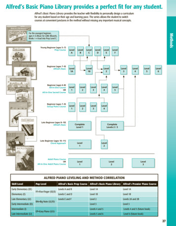
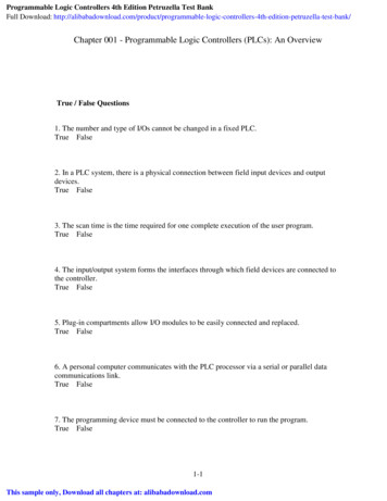
3PrefaceThe Festo Didactic Learning System for Automation and Technology isdesigned to meet a number of different training and vocational requirements, and the training packages are structured accordingly: Basic packages convey basic knowledge spanning a wide range oftechnologies Technology packages deal with important areas of open and closedloop control technology Function packages explain the basic functions of automated systems Application packages provide basic and further training closely oriented to everyday industrial practiceThe technology packages encompass pneumatics, electro-pneumatics,control pneumatics, programmable logic controllers, hydraulics, electrohydraulics, proportional hydraulics and control hydraulics.Fig. 1:Pneumatics –i.e. mobile workstationMounting FrameProfile PlateU 230 V p 6 MPaStorage tray Festo Didactic093314
4The modular design of the learning system permits applications beyondthe limits of the individual packages. PLC actuation, for example, istherefore possible of pneumatic, hydraulic and electrical actuators.All learning packages have an identical structure: Hardware Teachware Software CoursesThe hardware consists of industrial components and installationsadapted for didactic purposes.The courseware is matched methodologically and didactically to thetraining hardware. The courseware comprises: Textbooks (with exercises and examples) Workbooks (with practical exercises, worksheets, supplementarynotes, solutions and data sheets) Overhead transparencies and videos (as a visual means of teachingsupport)The teaching and learning media are available in several languages.They have been designed for use in classroom teaching, but can alsobe used for self-study purposes.In the software field, computer-based training programs, computer simulating programs, CAD programs and programming software for programmable logic controllers are available.Festo’s Didactic range of products for basic and further training is completed by a comprehensive selection of courses matched to the contentsof the technology packages. Festo Didactic093314
5Table of contentsTechnology package TP30113Layout of this workbook14Component/exercise table15Equipment set TP30116Notes on safety17Operating notes18Section A – CourseComponents of a programmable logic controllerExercise 1:Design and commissioning of a programmablelogic controllerComponents of a PLCA-3Programming to EN 61131 (IEC 61131)Exercise 2:From problem to solution –taking into consideration EN 61131 (IEC 61131)Practical steps for PLC programmingA-11Basic logic operationsExercise 3:Lamp circuitThe assignment functionA-19Exercise 4:Burglar alarmThe NOT functionA-29Exercise 5:Press with protective guardThe AND functionA-39Exercise 6:Bell systemThe OR functionA-49 Festo Didactic093314
6Logic control systems without latching propertiesExercise 7:Stamping deviceCombination of AND/OR/NOTA-59Exercise 8:Silo control system for two bulk materialsCombination circuit with branchingA-69Logic control systems with latching propertiesExercise 9:Fire alarmSetting an outputA-77Exercise 10:Drill breakage monitoringSetting and resetting an outputA-85Exercise 11:Activating a cylinderSignal edgesA-95Logic control systems with time responseExercise 12:Bonding of componentsPulseA-107Exercise 13:Embossing deviceSwitch-on signal delayA-117Exercise 14:Clamping deviceSwitch-off signal delayA-127Sequence control systemsExercise 15:Lifting device for packagesLinear sequenceA-137Exercise 16:Lifting and sorting device for packagesAlternative branchingA-155Exercise 17:Stamping device with counterCounting cyclesA-167 Festo Didactic093314
7Section B – FundamentalsChapter 1 Automating with a PLCB-11.1IntroductionB-11.2Areas of application of a PLCB-21.3Basic design of a PLCB-51.4The new PLC standard EN 61131 (IEC 61131)B-8Chapter 2 FundamentalsB-112.1The decimal number systemB-112.2The binary number systemB-112.3The BCD codeB-132.4The hexadecimal number systemB-132.5Signed binary numbersB-142.6Real numbersB-142.7Generation of binary and digital signalsB-15Chapter 3 Boolean operationsB-193.1Basic logic functionsB-193.2Further logic operationsB-233.3Establishing switching functionsB-253.4Simplification of logic functionsB-283.5Karnaugh-Veitch diagramB-30 Festo Didactic093314
8Chapter 4 Design and mode of operation of a PLCB-334.1Structure of a PLCB-334.2Central control unit of a PLCB-354.3Function mode of a PLCB-374.4Application program memoryB-394.5Input moduleB-414.6Output moduleB-434.7Programming device/Personal computerB-45Chapter 5 Programming of a PLCB-475.1Systematic solution findingB-475.2EN 61131-3 (IEC 61131-3) structuring resourcesB-505.3Programming languagesB-54Chapter 6 Common elements of programming languagesB-576.1Resources of a PLCB-576.2Variables and data typesB-606.3ProgramB-70Chapter 7 Function block diagramB-857.1Elements of function block diagramB-857.2Evaluation of networksB-857.3Loop structuresB-87Chapter 8 Ladder diagramB-898.1Elements of ladder diagramB-898.2Functions and function blocksB-928.3Evaluation of current rungsB-93 Festo Didactic093314
9Chapter 9 Instruction tions and function blocksB-97Chapter 10 Structured Selection statementsB-10310.4Iteration statementsB-106Chapter 11 Sequential function chartB-11111.1IntroductionB-11111.2Elements of sequential function ampleB-135Chapter 12 Logic control systemsB-13912.1What is a logic control systemB-13912.2Logic control systems without latching propertiesB-13912.3Logic control systems with memory functionB-14512.4Edge evaluationB-148Chapter 13 TimersB-15313.1IntroductionB-15313.2Pulse timerB-15413.3Switch-on signal delayB-15613.4Switch-off signal delayB-158 Festo Didactic093314
10Chapter 14 CounterB-16114.1Counter functionsB-16114.2Incremental counterB-16114.3Decremental counterB-16514.4Incremental/decremental counterB-167Chapter 15 Sequence control systemsB-16915.1What is a sequence control systemB-16915.2Function chart to IEC 60848B-169Chapter 16 Commissioning andoperational safety of a PLCB-17516.1CommissioningB-17516.2Operational safety of a PLCB-177Chapter 17 CommunicationB-18317.1The need for communicationB-18317.2Data ion in the field areaB-185ABibliography of illustrationsB-187BBibliography of literatureB-189CGuidelines and standardsB-191DGlossaryB-193EIndexB-199Appendix Festo Didactic093314
11Section C – SolutionsSolution 1:Design and commissioning of a programmablelogic controllerC-3Solution 2:Practical steps for PLC programmingC-5Solution 3:Lamp circuitC-7Solution 4:Burglar alarmC-11Solution 5:Press with protective guardC-15Solution 6:Bell systemC-21Solution 7:Stamping deviceC-25Solution 8:Silo control system for two bulk materialsC-31Solution 9:Fire alarmC-35Solution 10:Drill breakage monitoringC-39Solution 11:Activating a cylinderC-43Solution 12:Bonding of componentsC-47Solution 13:Embossing deviceC-53Solution 14:Clamping deviceC-57Solution 15:Lifting device for packagesC-63Solution 16:Lifting and sorting device for packagesC-69Solution 17:Stamping device with counterC-75 Festo Didactic093314
12 Festo Didactic093314
13Technology package TP301“ Programmable logic controllers“The technology package TP301 "Programmable logic controllers" is acomponent part of the Festo Didactic Learning System for Automationand Technology and forms the basic level of TP300.The training aims of TP301 are to learn how to program programmablelogic controllers and to teach the fundamentals for creating programs inthe programming languages ’ladder diagram’ (LD), ’function block diagram’ (FBD), ’instruction list’ (IL), ’structured text’ (ST) and ’sequentialfunction chart’ (SFC). Programming is effected in accordance with EN61131-3 (IEC 61131-3).You have the option of using this workbook in conjunction with alternative programmable logic controllers by different manufacturers.A basic knowledge of electro-pneumatics and sensor technology is recommended to work through technology package TP301.The exercises in TP301 deal with the following main topics: Components of a programmable logic controller PLC programming to EN 61131 (IEC 61131) Basic logic operations Logic control systems Sequence control systemsThe allocation of components and exercises can be seen from the component/exercise table. Festo Didactic093314
14Layout of this workbookThe workbook is structured as follows:Section A – CourseSection B – FundamentalsSection C – SolutionsSection D – AppendixSection A – Course teaches the programming of programmable logiccontrollers with the help of a series of progressive exercises.Any necessary technical knowledge required for the implementation ofan exercise is provided at the beginning. Functions are limited to themost elementary requirements. More detailed knowledge may be gainedin section B.Section C – Solutions provides the solutions to the exercises with briefexplanations.Section B – Fundamentals contains generally applicable technicalknowledge to supplement the training contents of the exercises in Section A. Theoretical links are established and the necessary technicalterminology explained with the help of examples. An index provides aneasy means of locating terminology.Section D – Appendix which contains data sheets of the used components. Festo Didactic093314
15Allocation of component and exerciseDescription123456Signal input, electrical1111Signalling device and distributor, electrical118910111213141111111111Proximity sensor, opticalProximity sensor, inductive711Proximity sensor, capacitive11111111Proximity sensor with cylindermounting5/2-way single solenoid valve11121115/2-way double solenoidvalveDouble-acting cylinder1512Single-acting cylinder171111111444412221122111116111112On/off valve with filter regulator valve1111111111Manifold1111111111 Festo Didactic093314
16Equipment set TP301Equipment set TP301Order No.:167101DescriptionOrder No.QuantityPlastic tubing151496Manifold1528691Single-acting cylinder1528871Double-acting cylinder1528882On/off valve with filter regulator valve1528941Quick push-pull distributor1531281Signal input, electrical1622421Signalling device and distributor, electrical1622441Proximity sensor with cylinder mounting16706045/2-way single solenoid valve16707425/2-way double solenoid valve1670761Proximity sensor, inductive1785741Proximity sensor, capacitive1785751Proximity sensor, optical1785771Order No.Quantityoptional, not included in scope of delivery of equipment setI/O data cable, digital034031Plug-in adapter035651Universal connection unit162231Power supply unit162416Set of cables167091 Festo Didactic093314
17Notes on safetyThe following notes should be followed in the interest of safety: Mount all components securely on the board. Do not switch on compressed air until all line connections have beenestablished and secured. Proceed with care when switching on the compressed air.Cylinders may advance or retract as soon as the compressed air isswitched on. Switch off air supply immediately if air lines become detached. Thisprevents accidents. Do not disconnect air lines under pressure. Do not exceed the permitted working pressure of 8 bar (800kPa). Observe general safety regulations in accordance with EN 60204-1(IEC 60204-1). Use only extra-low voltages of up to 24 V DC. Observe the data sheets referring to the individual components, inparticular all notes regarding safety. Festo Didactic093314
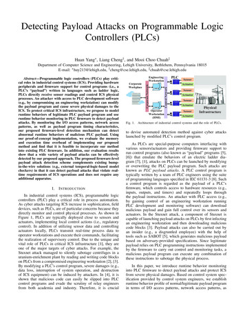
18Operating notesThe following rules should be observed when constructing a circuit: Block output 2 of the valve, if a single-acting cylinder is actuated by a5/2-way single solenoid valve in a circuit.Fig. 2:Plug for output 2of a 5/2-way valve42531 Input signals, which would result from an actual production processsequence, are reproduced in part by signals via push buttons orswitches. Festo Didactic093314
A-1Section A – CourseComponents of a programmable logic controllerExercise 1:Design and commissioning of a programmablelogic controllerComponents of a PLCA-3Programming to EN 61131 (IEC 61131)Exercise 2:From problem to solution –taking into consideration EN 61131 (IEC 61131)Practical steps for PLC programmingA-11Basic logic operationsExercise 3:Lamp circuitThe assignment functionA-19Exercise 4:Burglar alarmThe NOT functionA-29Exercise 5:Press with protective guardThe AND functionA-39Exercise 6:Bell systemThe OR functionA-49Logic control systems without latching propertiesExercise 7:Stamping deviceCombination of AND/OR/NOTA-59Exercise 8:Silo control system for two bulk materialsCombination circuit with branchingA-69 Festo Didactic093314
A-2Logic control systems with latching propertiesExercise 9:Fire alarmSetting an outputA-77Exercise 10:Drill breakage monitoringSetting and resetting an outputA-85Exercise 11:Activating a cylinderSignal edgesA-95Logic control systems with time responseExercise 12:Bonding of componentsPulseA-107Exercise 13:Embossing deviceSwitch-on signal delayA-117Exercise 14:Clamping deviceSwitch-off signal delayA-127Sequence control systemsExercise 15:Lifting device for packagesLinear sequenceA-137Exercise 16:Lifting and sorting device for packagesAlternative branchingA-155Exercise 17:Stamping device with counterCounting cyclesA-167 Festo Didactic093314
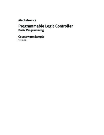
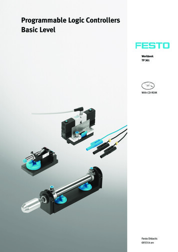
A-3Exercise 1Programmable logic controllersSubjectDesign and commissioning of a programmable logic controllerComponents of a PLCTitle To be able to explain the basic design and mode of operationof a PLC To be able to configure and commission a PLCNowadays, programmable logic controllers form part of any automationprocess. Fig. A1.1 illustrates the typical configuration of an automationsolution realised by means of a PLC. The control system shown represents the simpler, non-networked group of PLC applications.PC /Programming deviceDisplay/Control unitPLCSensorsActuators Festo Didactic093314Training aimTechnical knowledgeFig. A1.1:Automation via PLC
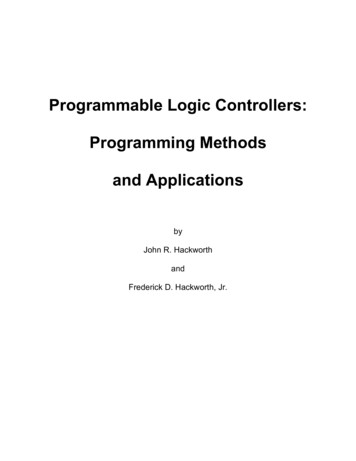
A-4Exercise 1The basic components of the control system are: Programmable logic controller (PLC)By this, we understand the electronic modules through which all ofthe system or machine functions to be controlled are addressed andactivated in a logic sequence. SensorsThese components are located directly on the system or machinerybe controlled, through to which the PLC is communicated actual statuses. ActuatorsThese components are located directly on the system or machineryto be controlled, through which the PLC is able to change or influencestatuses and as such the technical process. PC or programming deviceThis is used to create the program containing the logic of the systemor machinery to be controlled and to transfer this to the memory ofthe PLC. At the same time, these programming tools also providesupporting functions for the testing of the PLC program and commissioning of the controller. Display and control unitsThese enables you to monitor and influence the operation of the system or machinery.Programmable logic controllerThe most important component of a control system is the PLC and itsprogram. Fig. A1.2 illustrates the system components of a PLC.Fig. A1.2:System componentsof a PLCPLC-programInput moduleSensorsCentral control unitOutput moduleActuators Festo Didactic093314
A-5Exercise 1A PLC is connected to the system to be controlled via input and outputmodules. The system to be controlled supplies input signals (mostlybinary) via sensors to the input modules. These signals are processedwithin the main processing unit, the main component of the PLC. Prior.to formulation of IEC standards, known as "central control unit" (CCU).The "specification" for the processing of signals is defined in the PLCprogram. The result of the processing is output to the actuators of thesystem to be controlled via the output module. Thus, the design of aPLC corresponds to that of a computer.PLC programPLC programs consist of a logic sequence of instructions. The controlprogram is stored in a special, electronic readable memory, the socalled program memory of the PLC. Special RAMs with back-up batteryare used during the program development, since its contents can alwaysbe changed again very quickly.After commissioning and error-free function of the controller it is a goodidea to transfer the PLC program unerasably to a read-only memory,e.g. an EPROM. If the program is executed, it will be processed in continuous cycles.SignalsInput signals reach the PLC via sensors. These signals contain information about the status of the system to be controlled. It is possible toinput binary, digital and analogue signals.A PLC can only recognise and output electrical signals. For this reason,non-electrical signals are converted into electrical signals by the sensors. Sensor examples are: Push buttons, switches, limit switches, proximity sensorsOutput signals influence the system to be controlled. The signals can beoutput in the form of binary, digital or analogue signals. Output signalsare amplified into switching signals via the actuators or converted intosignals of other energy forms. Actuators examples are: Lamps, buzzers, bells, contactors, cylinders with solenoid valves,stepper motors Festo Didactic093314
A-6Exercise 1Problem descriptionA control task is to be solved via a programmable logic controller (PLC).Familiarise yourself with the basic design of a PLC.Positional sketchExercise definition1. Components of a PLC2. Design and commissioning of the PLC you have selectedImplementationTo carry out the exercise using the worksheets, refer to Section B of theworkbook and your PLC data sheet or manual. Festo Didactic093314
A-7Exercise 1WORKSHEET1.1 Components of a PLCQuestion 1:What are the basic components of a programmable logic controller?Question 2:What are the basic modules making up the central control unit of a programmable logic controller? Festo Didactic093314
A-8Exercise 1Question 3:How is electrical isolation achieved between sensor/actuator signals andthe PLC? Festo Didactic093314
A-9Exercise 1WORKSHEET1.2 Design and commissioning of the PLC you have selectedEnter the technical data of the selected programmable logic controller inthe table below.CriteriaTechnical dataOperating voltageNominal voltagePermissible voltage rangeCurrent consumptionInputsNumberInput currentInput levelOutputsNumberSwitching logicOutput voltageOutput currentConfigure the PLC in accordance with the notes in the relevant datasheet or manual. Festo Didactic093314Technical data
A-10Exercise 1 Festo Didactic093314
C-1SolutionsSection C – SolutionsComponents of a programmable logic controllerSolution 1:Design and commissioning of aprogrammable logic controllerComponents of a PLCC-3Programming to EN 61131 (IEC 61131)Solution 2:From problem to solution –taking into consideration EN 61131 (IEC 61131)Practical steps for PLC programmingC-5Basic logic operationsSolution 3:Lamp circuitThe assignment functionSolution 4:Burglar alarmThe NOT functionC-11Solution 5:Press with protective guardThe AND functionC-15Solution 6:Bell systemThe OR functionC-21C-7Logic control systems without latching propertiesSolution 7:Stamping deviceCombination of AND/OR/NOTC-25Solution 8:Silo control system for two bulk materialsCombination circuit with branchingC-31 Festo Didactic093314
C-2SolutionsLogic control systems with latching propertiesSolution 9:Fire alarmSetting an outputC-35Solution 10:Drill breakage monitoringSetting and resetting an outputC-39Solution 11:Activating a cylinderSignal edgesC-43Logic control systems with time responseSolution 12:Bonding of componentsPulseC-47Solution 13:Embossing deviceSwitch-on signal delayC-53Solution 14:Clamping deviceSwitch-off signal delayC-57Sequence control systemsSolution 15:Lifting device for packagesLinear sequenceC-63Solution 16:Lifting and sorting device for packagesAlternative branchingC-69Solution 17:Stamping device with counterCounting cyclesC-75 Festo Didactic093314
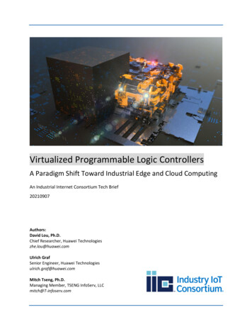
C-3Solution 1Design and commissioning of a programmable logic controllerComponents of a PLCTitle.1 1.1 Components of a PLCWhat are the basic components of a programmable logic controller?Question 1The basic components of a PLC are:Answer the main processing unit, formerly (central control unit) the input modules the output modules the program memory the PLC programWhat are the basic modules making up the main processing unit of aprogrammable logic controller?Question 2The basic modules of an MPU are:Answer the control unit the data memory the arithmetic and logic unit (ALU)How is electrical isolation achieved between sensor/actuator signals andthe PLC?Question 3The sensor/actuator signals and the PLC are electrically isolated via anoptocoupler. The main processing unit is thus separated from the external circuit of the sensors and actuators. Interferences in these circuitstherefore cannot damage the controller.AnswerInputsignalErrorvoltagedetection Festo Didactic093314SignaldelayOptocouplerBlock diagram of aninput moduleSignal tothecontrol unit
C-4Solution 1.2 1.2 Design and commissioning of your selected PLCThe following table lists the technical data of a Festo FPC 101B programmable logic controller as an example.Technical dataCriteriaTechnical dataOperating voltageNominal voltage24 V DCPermissable voltage range16 to 30 VDCCurrent consumptionapprox. 160 mAInputsNumber21of which 1 is a counter inputInput voltage6 mAInput levellog. 0 0 to 5 Vlog. 1 11 to 30 VOutputsNumber14 Transistor outputsTypepositive switchingOperating voltage – 2 VOutput voltageOutput currentmax. 300 mA/outputTotal output current max. 2.5 A Festo Didactic093314
Solution 1: Design and commissioning of a programmable logic controller C-3 . Solution 2: Practical steps for PLC programming C-5 . Solution 3: Lamp circuit C-7 . Solution 4: Burglar alarm C-11 . Solution 5: Press with protective guard C-15 . Solution 6: Be