Transcription
MULTISLIDE DOORINSTALLATION GUIDE10507 East MontgomerySpokane Valley, WA 99206(800) 442-8544www.cascadewindows.com
MULTISLIDE DOORINSTALLATION INSTRUCTIONSCONTENTSTHINGS TO KNOW.3KD OR KNOCK DOWN FRAME BUILD.4FRAME INSTALLATION.6PANEL INSTALLATION.8LOCK AND HARDWARE INSTALLATION.9CAPS AND PANEL STOP INSTALLATION.10CAPS AND SECURIING O PANEL.11STANDARD HARDWARE W/ KEY LOCK.12SIGNATURE SERIES W/ KEY LOCK.13EXPLODED FRAME VIEW.14Page 2
MULTISLIDE DOORINSTALLATION INSTRUCTIONSTHINGS TO KNOWHazard NotationsMistakes orHeavy object.misuse couldUnassistedcause damagelifting may causeto the product orinjury.result in a faultyinstallation.Information onhelpful tipsandprocedures.Tools neededSupplies needed#2 Phillips ScrewdriverPry BarDrillSquareTape MeasureFine Tooth Chop SawSafety GlassesUtility KnifeLevelHammerMalletConstruction AdhesiveFlashingShimsStaplesLow Expanding FoamDoor PanSAFETY & HANDLING Understand ALL manufacturer’s instructions before beginning to install your Cascade product.Do not work alone. Use safe lifting techniques. Always wear your P.P.E. (e.g. safety glasses,gloves, ear protection, etc.). Use caution when handling glass.Operate hand/power tools safely and follow themanufacturer’s operation instructions.HOW TO CHECK PLUMB, LEVEL AND SQUAREA & B - Cross tape measurements to verify theopening is square.C - Threshold level, free of any crowns and sags.D - Plumb vertical jamb.E - Plumb vertical exterior portion of the wall.Page 3Do not put stress on corners of frames.Store door in a well-ventilated area in avertical, leaning position to allow air circulation.Protect from exposure to direct sunlight duringstorage.Install only into vertical walls and whenconditions and sheathing are dry.
MULTISLIDE DOORINSTALLATION INSTRUCTIONSKD OR KNOCK DOWN FRAME BUILDAfter you have unpacked the frame, start byidentifying the sill (the sill can be identified bythe weep holes), head and jambs. Be sure toassemble the frame one corner at a time. Sawhorses are recommended to keep the frameprofiles off the ground and safe from damageduring assembly.1. You will notice that the butt ends of thejambs have joining gaskets. Using theprovided alcohol wipes (Fig. 1), cleanthe area where the jamb gaskets will beadhering to on the head and sill.(Fig. 1)(Fig. 2)2. Remove the liner from the jamb gaskets(Fig. 2). Repeat the steps for the other jambto sill/header joints.3. Insert the packaged frame build screws intothe pre-drilled holes in the jamb (Fig. 3).Pan head screws will go in the recessedsections of the frame. The washer headscrews will go in the holes with the flatsurface. One corner at a time, make sureeach screw is aligned with the proper screwboss, and tighten each screw evenly untilthe jamb is tightened firmly against thesill and/or header. Be careful not to overtorque and strip out the vinyl, or pull throughthe jamb’s walls. There should be a slightdimple in the frame where the washer headscrews are applied.(Fig. 3)(Fig. 4)4. Remove the paper backing of the Seal Tapeto expose the sticky side of the tape (Fig.4). Apply the provided Seal Tape to thejamb-sill joint on both sides (Fig. 5).(Fig. 5)Page 4
MULTISLIDE DOORINSTALLATION INSTRUCTIONSKD OR KNOCK DOWN FRAME BUILD5. Once the tape has been applied, remove theMylar backing (Fig. 6). Firmly rub one cornerin and use your finger nail to get the edge ofthe Mylar backing to peel off. Once the Mylarbacking has been removed, make sure youwork the tape into any voids in the frame toensure a good seal. (Fig. 7)6. Use the provided SM5555 caulking to sealthe interior joint, sill to jamb. You will need toslide the tracks out of your way in order to dothis step correctly. (Fig. 8)(Fig. 6)7. Last step, apply the nail fin corner. Usingthe SM5555 seam sealer, fill the outer mosthole on top of the frame as well as apply abead of seam sealer to the nail fin on thejamb and header (Fig. 9). Firmly apply thenail fin corner into place. Make sure the nailfin corner is on the outer portion of the framemounted to the face of the frame (Fig. 10).Page 5(Fig. 7)(Fig. 8)(Fig. 9)(Fig. 10)
MULTISLIDE DOORINSTALLATION INSTRUCTIONSGENERAL INSTALLATION INSTRUCTIONS1. INSPECT PRODUCT AND CARE 2. INSPECT THE ROUGH OPENINGCarefully remove any shipping materials.(e.g. corner covers, shipping blocks, plasticwrap, etc.)Check for any cosmetic damages.Correct product. (size, color, handing, etc.)Use provided QC check list to make sure allparts are accounted for in the hardware box.If any of the above conditions are a concern,contact your dealer or Distributer forrecommendations prior to installation. Verify the width and height of the opening forproper clearance.Verify the opening is square by measuringdiagonally from one corner to the other onboth sides.Verify the opening is level and plumb.These steps are important to acquire a troublefree installation. If these conditions are not met,you will need to adjust accordingly.FRAME INSTALLATION1. Build your frame. (see installationinstructions for KD or KNOCK DOWNframes)2. Clean and level the threshold thoroughly.Shims must be placed no more than 2 inchesapart, as well as the entire depth of theframe’s threshold.With multiple tracks it’s veryimportant to make sure thethreshold is level the length of theopening and the distance from theinterior to exterior. (Fig. A & B)**FAILURE TO PROVIDE ANADEQUATE PAN, WITH A WOODTHRESHOLD, WILL VOID ITSWARRANTY.**It is necessary to have assistance whencarrying the unit as well as removingand installing the panels.Page 6(Fig. A)OR(Fig. B)Proper steps must be taken whenflashing and applying sealant to ensureproper waterproofing of the unit.
MULTISLIDE DOORINSTALLATION INSTRUCTIONSFRAME INSTALLATION CONWhen installing a three track MultiSlideyour screw pattern should be every 16inches in the outer and inner track. Inthese tracks, make sure your screws arenot on the die line but towards the center of theframe, if the screws are exposed and need tobe pre drilled. (Fig. C). When installing a fourtrack MultiSlide your screw pattern should beevery 16 inches in the outer track and the twoinner tracks. Make sure your screws are not onthe die line but towards the center of the frame,if the screws are exposed and need to be predrilled. (Fig. D)3. Flash the opening according to AAMAstandards.4. Apply two 3/8” beads of polyurethane to theentire length of the threshold, above andbelow any shims and surrounding areas.5. Set the frame of the door into the openingand walk across the threshold to compressthe sealant.6. With the frame screws provided (Fig. E),secure the four corners and one screw in themiddle of the header to eliminate saggingand misreading’s when cross taped forsquareness. (Fig. F)7. Cross tape your frame to make sure theframe is square. (Fig. G)8. Place a level on the jamb to make sure itsplumb interior to exterior.IT IS VERY IMPORTANT TO MAKESURE THAT THE JAMB IS PLUMBFROM THE EXTERIOR TO THEINTERIOR. IF THE JAMB HASANY KIND OF BOW IN IT, IT WILLIMPEDED THE OPERATION OF THEDOOR AND THE DOOR WILL MOSTLIKELY KNOCK WHEN THE PANELIS SHUTPage 73 track screwplacement. Donot pre-drill 3/8holes on thedie lines.4 track screwplacement. Donot pre-drill 3/8holes on the dielines.(Fig. C)(Fig. D)(Fig. E)(Fig. F)(Fig. G)
MULTISLIDE DOORINSTALLATION INSTRUCTIONSPANEL INSTALLATION9. Secure the jamb and header of the frameplacing the screws in the appropriate tracks,(Fig. C & D, previous page) no more than 16inches apart and roughly 3-6 inches from thecorners. Use a level to make sure the jambis plumb side to side and there is no daylightbetween the level and the frame. Level andsecure the header making sure it’s perfectlystraight. (Fig. H)10. Install the first X panel into the inner mosttrack.11. Raise the wheel adjustment using a Philipshand screwdriver. (Fig. I) On a 3750 door, the panel should be raised2 5/8 from the top of the parting bead tothe bottom of the glazing bead. (Fig. J) On a 2750 door, raise the wheeladjustment to its max height.Be careful not to over torque the screws. It’ssuggested to tip one corner up to take the weightoff of the wheel.12. Slide the panel to each jamb and look at thereveals. (Fig. K)13. Install the 2nd panel following the same ruleas step 11.14. Check the reveal with the 2nd panel againstthe stacking side jamb. It should be even andstraight just as the first panel.15. Hold the locking active panel and the 2ndpanel together and slide them as one. Checkto see if the panels are sliding evenly togetherwithout shifting opposite of each other.16. Follow steps 11-16 for your 3rd active panel ifyou have a 4-track door.17. After all the panels are installed, adjust theframe as necessary to get the acquiredreveals(Fig. H)(Fig. I)(Fig. J)(Fig. K)Page 8
MULTISLIDE DOORINSTALLATION INSTRUCTIONSLOCK AND HARDWARE INSTALLATION18. Make sure the O Panel setting blocksare positioned correctly. One should bepositioned near the jambs corner and theother block should be placed approximatelywhere the other edge of the O panel will sit.19. Install the O panel into the head of the frameand onto the setting blocks. Push the panelcompletely into the jamb pocket. **Do notsecure the O panel into place at thismoment**20. If the door does not have flush mountedhardware you will need to install the handlehardware now. (see hardware diagram page12 & 13)21. Install the keeper. Lock the keeper onto thedoor panel. Slide the door close to the jamband mark the frame where the top of thekeeper is positioned. (Fig. L)22. Unhook the keeper from the panel and set itin the jamb, lining it up with the pencil marktransferred to the frame. Use the die linein the center of the pocket for the centerreference; mark the center of the top andbottom holes on the frame.23. With the keeper screws provided, secure thekeeper onto the frame.24. Slide the panel close to the frame to checkthat the frame has no bows. **Do not overtighten the keeper screws and bow theframe.**25. Slide the X panel into the jamb and test thelock.26. With the keeper installed and lockingcorrectly, finish off the last screw. Place thescrew at the top of the center oval hole. Bydoing this, it will lock your keeper in placewhich in turn will help eliminate service issuesin the future.27. Place shims between the framing of theopening and the door’s frame where thekeeper is located. Make sure the shims arefirmly in place to eliminate any movement(shim every 16 inches on the jambs andevery 24 inches on the header). (Fig. M)Shimbehindkeeper(Fig. L)(Fig. M)When installing any hardwarealways use a #2 Philips handscrewdriver.IMPORTANT NOTE- If installing standardhardware with no key lock, you MUST use thefiller piece in place of the key lock (Fig. N).Failure to do so could compromise the securityof the product.(Fig. N)Page 9
MULTISLIDE DOORINSTALLATION INSTRUCTIONSCAPS AND PANEL STOP INSTALLATION28. Install the strike side jamb caps. **Add dabsof polyurethane on both sides of thepocket, top and bottom as well as every16inches between. This will help eliminateany movement of the caps.**29. Installing the header and threshold caps.Shut the door completely; the hardwareshould be about 1/16” away from theparting bead of the frame. Push back theother panels making sure the interlocks arecompletely engaged but the main activepanel is still in the position noted above.30. Mark on the sill and header of the framewhere each panel ends.31. Measure from your line to the jamb’s partingbead and deduct 1/8”. Keep in mind thethickness of the bumper on the X panel track/tracks needs to be included in the overallsize. For the O panel just measure from thejamb’s parting bead to the panel and deduct1/8”.**In the end, there needs to be at least 1/8”gap between any sill and header cap.**Panel Stop InstallationIf you ordered a 3750 door without the flushmount hardware or ordered a 2750 door, thedoor will come with a Panel Stop and screws.This is needed on the 2nd panel. The purposeof the Panel Stop is to stop the active panelbefore the handle hardware hits the 2nd panel.On both the 2750 and 3750 door the panel stopshould be mounted 1 ½“ from the back of the2nd panel, and just above the glazing bead. Ifthe panel is not drilled out you will need to alignthe panel stop in the proper position and markwhere to drill. Completely open the door andmake sure the panel stops at the stop beforethe handle hardware makes contact with the2nd panel. Once sure of the placement, predrill with a 9/64 bit and secure with the screwsprovided.Panel Stop1 1/2”2750 Placement1 1/2”3750 PlacementINSTALLATION OF TOP AND BOTTOM CAPSTrimming the caps is one of the most important steps of installing these doors.Failure to allow for proper clearance will result in faulty operation and damage to theproduct. If the Threshold Cap is installed tight it can split the main frame at the corner dueto thermal expansion of the aluminum. This will not be covered under warranty. If the capsfor the other X panels don’t have the proper clearance, it could result in the door not lockingproperly.Page 10
MULTISLIDE DOORINSTALLATION INSTRUCTIONSCAPS AND SECURIING O PANEL32. Install the threshold caps. The rounded endof the outer most cap faces the exterior. (Fig.O) Make sure to put the bumper in the middletrack/tracks.33. Install the top caps. **Add dabs ofpolyurethane on both sides of the pocket,top and bottom as well as every 16inchesbetween. This will help eliminate anymovement of the caps.** Be careful not togo further than the length of the caps withbumpers. Make sure to put the bumper in themiddle track/tracks.34. Slide the door shut and check for properclearance and operation of the lock.35. With the fixed panel screws provided (Fig.P), secure the O panel. Place screws in theparting bead where the weather stripping islocated. Secure the panel at the top, bottomand middle. (Fig. Q)36. Install the interior stacking side jamb caps.37. On new construction doors, finish off thescrews on the nail fin, as well as the sealantand flashing, according to industry standards.38. Install button plugs in any 3/8” pre-drilledholes, including the wheel adjustment holes.(Fig. O)(Fig. P)Placefixed panelscrewshere.(Fig. Q)Page 11
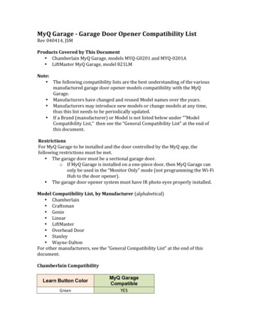
MULTISLIDE DOORINSTALLATION INSTRUCTIONSSTANDARD HARDWARE W/ KEY LOCKPage 12
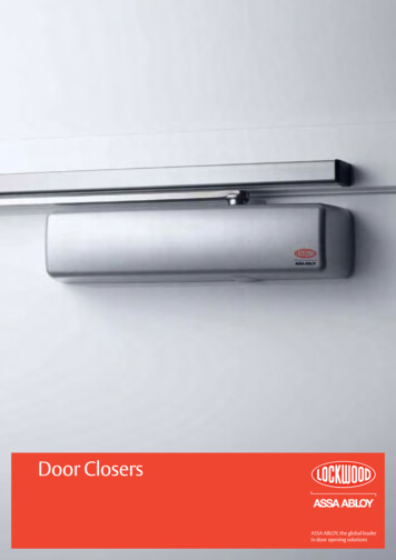
MULTISLIDE DOORINSTALLATION INSTRUCTIONSSIGNATURE SERIES W/ KEY LOCKPage 13
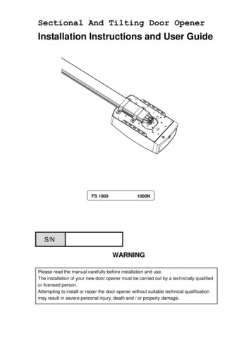
MULTISLIDE DOORINSTALLATION INSTRUCTIONSEXPLODED FRAME VIEWPage 14
MULTISLIDE DOORINSTALLATION INSTRUCTIONSPage 15
MULTISLIDE DOORINSTALLATION INSTRUCTIONSPage 16
MULTISLIDE DOORINSTALLATION INSTRUCTIONSPage 17
MULTISLIDE DOORINSTALLATION INSTRUCTIONSPage 18
MULTISLIDE DOORINSTALLATION INSTRUCTIONSPage 19
MULTISLIDE DOORINSTALLATION INSTRUCTIONSPage 20
20. If the door does not have flush mounted hardware you will need to install the handle hardware now. (see hardware diagram page 12 & 13) 21. Install the keeper. Lock the keeper onto the door panel. Slide the door close to the jamb and mark the frame where the top of the keeper is positioned. (Fig. L) 22. Unhook the keeper from the panel and .