Transcription
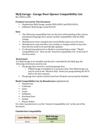
Sprinter Door Adjustment SupplementDOOR ADJUSTMENT PROCEDURESProper door adjustment is essential in applications with extended use of sliding doorand rear cargo doors. Misadjusted doors will reduce the service life of door hinges andrelated parts.This module covers the adjustment procedures for:Sliding doorsRear hinged cargo doorsFigure 1 Sprinter Sliding Door1
Sprinter Door Adjustment SupplementSLIDING DOOR ADJUSTMENT PROCEDURE1.Check the sliding door gap all the way around (Figure 2). The gap nominal value is7 mm 0.5 (0.276 in 0.019).1Sliding Door GapFigure 2 Sliding Door Gap2.Check the sliding door ridge at the B-pillar and side panel areas (Figure 3). Thedoor ridge should be flush without offset.1Rear Ridge Pattern2Front Ridge PatternFigure 3 Sliding Door Ridge Pattern2
Sprinter Door Adjustment Supplement3.Tighten door stabilizer receiver bolts to 10 N·m (89 in. lbs). See Figure 4.121Receiver Bolts (Torx)2Stabilizer ReceiverFigure 4 Door Stabilizer Receiver4.Loosen stabilizer closing wedge bolts to allow wedge to move. It must be possibleto move the closing wedge during the entire adjusting procedure. In order to closethe door during adjustment move guide wedge if necessary (Figure 5).121Wedge Bolts (Torx)2Stabilizer Closing WedgeFigure 5 Door Stabilizer Closing Wedge3
Sprinter Door Adjustment Supplement5.Loosen center roller arm bolt and adjust rear ridge pattern by lifting or loweringsliding door (Figure 6). Tighten center roller arm bolt.1231Center Roller Arm2Rear Ridge Pattern3Allen BoltFigure 6 Rear Ridge Pattern Adjustment6.7.Loosen upper roller arm bolts (Figure 7). Loosen lower roller arm bolts.Adjust front ridge pattern at upper roller arm by raising or lowering the slidingdoor.3121Front Ridge Pattern2Upper Roller Arm Bolt (Torx)3Lower Roller Arm Bolt (Torx)Figure 7 Front Ridge Pattern Adjustment4
Sprinter Door Adjustment Supplement8.9.Tighten upper and lower roller arm bolts to 25 N·m (18 ft. lbs).Loosen latch striker bolts and adjust to the modified door position by movingstriker vertically (arrow). See Figure 8.121Striker2Striker Bolts (Torx)Figure 8 Latch Striker10.Tighten latch striker bolts to 25 N·m (18 ft. lbs).NOTE: Do not lift or pull down the sliding door over the striker. When the ridge pattern is even, the bottom and top door gaps should be within the specified tolerancerange (Figure 9). For optical reasons a slightly wedge-shaped door gap at the top andbottom is preferable to a ridge offset.Figure 9 Bottom and Top Door Gaps5
Sprinter Door Adjustment Supplement11.Loosen center roller arm bolt and adjust side gaps by adjusting center roller armhorizontally (arrow). See Figure 10.12231Center Roller Arm2Side Gaps3Allen BoltFigure 10 Side Gap Adjustment12.Tighten center roller arm bolt (3).NOTE: To avoid wind noises, the sliding door flushness at B-pillar should be flush to 1mm (0.039 in.) recessed, and flush to 1 mm (0.039 in.) protruded at C-pillar (See steps13-14).13.Loosen upper and lower roller arm adjustment bolts (Figure 11).121Upper Adjustment Bolt (Allen)2Lower Adjustment Bolts (Allen)Figure 11 Front of Door Flushness Adjustment6
Sprinter Door Adjustment Supplement14.Adjust front of door flushness to B-pillar by altering the position of top and bottom roller arms.15. Tighten upper and lower roller arm adjustment bolts.16. Loosen latch striker bolts (See Figure 12).121Striker2Striker Bolts (Torx)Figure 12 Rear of Door Flushness Adjustment17.Adjust rear of door flushness by moving striker horizontally (arrow). See Figure12. Rear edge of sliding door should be flush or with a 1 mm (0.039 in.) protrusion. Tighten latch striker bolts to 25 N·m (18 ft. lbs).18. Loosen stabilizer closing wedge bolts (Figure 13).19. Adjust the position of the stabilizer closing wedges in relation to the stabilizerreceivers by moving the guide wedges (arrows A, B). See Figure 13.11Stabilizer Closing Wedge22Stabilizer ReceiverFigure 13 Stabilizer Closing Wedge Adjustment7
Sprinter Door Adjustment Supplement20.21.Close sliding door to center the stabilizer closing wedge at the receiver.Check front of door flushness in relation to B-pillar. The front of door should beflush or recessed 1 mm (0.039 in).22. Open door and tighten stabilizer closing wedge bolts to 10 N·m (89 in. lbs).23. Loosen door stop bumper bolts (See Figure 14).121Door Stop Bumper2Bolts (Torx)Figure 14 Door Stop Bumper24.25.Open sliding door and hold tight in end position.Hold door stop bumper tight against C-pillar and tighten bolts to 10 N·m (89 in.lbs).26. Inspect B-pillar rubber buffers. Replace if broken or missing to avoid damage toB-pillar when sliding door is closed with a swing. Glue upper rubber buffer to Bpillar approximately 30 mm (1.18 in.) above upper stabilizer receiver (Figure 15).130 mm(1.18 in.)21B-Pillar Top Rubber Buffer2Upper Stabilizer ReceiverFigure 15 B-Pillar Top Rubber Buffer8
Sprinter Door Adjustment Supplement27.Glue bottom rubber buffer to B-pillar approximately 35 mm (1.38 in.) below bottom stabilizer receiver (Figure 16).135 mm(1.38 in.)21Bottom Stabilizer Receiver2B-Pillar Bottom Rubber BufferFigure 16 B-Pillar Bottom Rubber BufferNOTE: Glue rubber buffers only to outer edge of B-pillar to avoid pinching the weatherstrip between the door and rubber buffer when closing the sliding door.28.Check sliding door for easy motion.9
Sprinter Door Adjustment SupplementREAR DOOR ADJUSTMENT PROCEDURE1.Check door gap around rear doors (Figure 17). The door gap all around except atthe top should be 8 mm 0.5 (0.315 in 0.019). The door gap at the top should be13 mm 0.5 (0.512 in 0.019).Figure 17 Rear Door Gap Measurements2.Open doors and loosen the hinge rounded-head torx bolts (Figure 18).10
Sprinter Door Adjustment Supplement121Door Hinge2Rounded-Head Torx BoltsFigure 18 Rear Door Hinge Bolts3.Close the door and check gap measurement. Loosen socket-head torx boltthrough hole in hinge (Figure 19).121Socket-Head Torx Bolt2Door HingeFigure 19 Door Hinge Socket-Head Torx Bolt4.5.Adjust rear door so that bottom closing wedges (Figure 21) make contact and doorgaps are uniform all the way around. Tighten socket-head torx bolt to 25 N·m (18ft. lbs).Open doors and tighten rounded-head torx bolts to 25 N·m (18 ft. lbs).11
Sprinter Door Adjustment Supplement6.Loosen door striker and adjust horizontally so right door is flush with the left door(Figure 20).NOTE: Striker should engage in latch at center. Door should not be lifted or pusheddownward with striker.7.Tighten door striker.121Door Striker2Left DoorFigure 20 Door Striker Adjustment8.Check adjustment of rear door closing wedges (See Figure 21). Closing wedges atbottom must be resting free of play on plastic closing plates when rear doors areclosed. To adjust, loosen door hinges and raise or lower complete doors.121Rear Door2Bottom Closing WedgeFigure 21 Rear Door Bottom Closing Wedges12
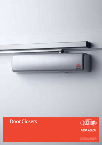
Sprinter Door Adjustment SupplementNOTE: Since the rear doors are involved with vehicle stability, it is important that therear doors fasten securely when the vehicle is moving. This prevents excessive torsionof the vehicle and leaky rear doors. The rear doors are fastened by adjusting the closing wedges.(0.59)(0.787)Construct a gauge block out of hardwood or plastic (See Figure 22). The gauge isrequired for adjusting the upper closing wedges on the rear doors.(0.16)75.2(57)(0.472)Figure 22 Gauge Block Dimensions in mm (inches)9.To adjust upper closing wedge of left rear door, push gauge block onto door at topnear lock pin so that the 12 mm-thick side (0.472 in.) faces the cargo space (Figure 23).121Gauge Block2Upper Closing WedgeFigure 23 Upper Closing Wedge Adjustment13
Sprinter Door Adjustment Supplement10.Close rear door until the gauge block makes contact below the roof drip molding.Adjust upper closing wedge so that it rests on plastic closing plate free of play.Tighten closing wedge screws to 10 N·m (89 in. lbs.).11. Adjust upper closing wedge of right rear door, so that it rests on plastic closingplate free of play when the rear door is closed. Tighten closing wedge screws to 10N·m (89 in. lbs.).NOTE: If the contact pressure is too low, leakage can occur on the seal of the left reardoor. To seal rear door, pad the vertical seal at the top using sealing strip (part number 000 989 97 98) to increase the contact pressure (See Figure 24).121Sealing Strip2Left Rear DoorFigure 24 Left Rear Door Sealing Strip12.Check and adjust the hinges. On rear doors, the retaining magnets should runup to the middle of the mating plate at the side wall. If this is not the case, correctas listed (Figure 25).NOTE: There are two adjustment allen setscrews on each rear door hinge. In somecases, an additional third allen setscrew may be found (Figure 25).CAUTION: Do not overadjust the allen setscrews (risk of control cam breaking). Theadjustment range of the allen setscrews is 1 turn MAXIMUM. See Figure 25.14
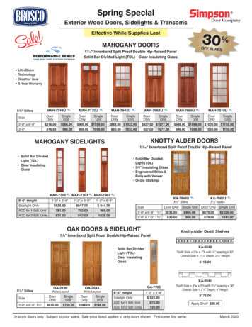
Sprinter Door Adjustment Supplement114321Control Cam3Additional Third Allen Setscrew2Adjustment Allen Setscrew4Adjustment Allen SetscrewFigure 25 Rear Hinge Adjustment SetscrewsRetaining magnet is too far forward relative to mating plate: Turn in adjustingscrew (2) at top and bottom hinge.Retaining magnet is too far back relative to mating plate: Turn out adjustingscrew (2) at top and bottom hinge.Retaining magnet is too deep relative to mating plate: Turn in adjusting screw (2)at top hinge, turn out adjusting screw (2) at bottom hinge.Retaining magnet is too high relative to mating plate: Turn out adjusting screw (2)at top hinge, turn in adjusting screw (2) at bottom hinge.Retaining magnet strikes too hard against mating plate. Turn in adjustmentscrew (3) at top and bottom hinge.Retaining magnet does not make contact with mating plate. Turn out adjustmentscrew (3) at top and bottom hinge.Door projects at corner paneling when closed: Turn out adjusting screw (4) athinge.Door is too far recessed at corner paneling when closed: Turn in adjusting screw(4) at hinge.13. Check rear doors for ease of movement.14. Finish paint in adjustment range of hinges on rear pillars using brush Since thehinges are already installed on the body shell at the factory it is not possible for acorrosion protection agent to adhere to the contact surfaces. The unprotectedareas must therefore be touched up after adjustment.15
Sprinter Door Adjustment Supplement 2 SLIDING DOOR ADJUSTMENT PROCEDURE 1. Check the sliding door gap all the way around (Figure 2). The gap nominal value is 7 mm 0.5 (0.276 in 0.019). Figure 2 Sliding Door Gap 2. Check the sliding door ridge at the B-pillar and side panel areas (Figure 3). The door ridge should be flush without offset.