Transcription
ESP8266 802.11bgn Smart DeviceESPRESSIF SMARTCONNECTIVITYPLATFORM: ESP82661 PageEspressif SystemsOct 12, 2013
ESP8266 802.11bgn Smart DeviceDisclaimer and Copyright NoticeInformation in this document, including URL references, is subject to change without notice.THIS DOCUMENT IS PROVIDED "AS IS" WITH NO WARRANTIES WHATSOEVER,INCLUDING ANY WARRANTY OF MERCHANTABILITY, NONINFRINGEMENT,FITNESS FOR ANY PARTICULAR PURPOSE, OR ANY WARRANTY OTHERWISEARISING OUT OF ANY PROPOSAL, SPECIFICATION OR SAMPLE. All liability, includingliability for infringement of any proprietary rights, relating to use of information in thisdocument is disclaimed. No licenses express or implied, by estoppel or otherwise, to anyintellectual property rights are granted herein.The Wi-Fi Alliance Member Logo is a trademark of the Wi-Fi Alliance.All trade names, trademarks and registered trademarks mentioned in this document are propertyof their respective owners, and are hereby acknowledged.Copyright 2013 Espressif Systems Inc. All rights reserved.2 PageEspressif SystemsOct 12, 2013
ESP8266 802.11bgn Smart DeviceTable of Contents12345INTRODUCTIONTECHNOLOGY OVERVIEWFEATURESAPPLICATION DIAGRAMULTRA LOW POWER TECHNOLOGY5.1 HIGHEST LEVEL OF INTEGRATION67ESP8266 APPLICATIONSSPECIFICATIONS7.1 CURRENT CONSUMPTION910107.2118456788RF PERFORMANCECPU, MEMORY AND INTERFACES8.1 CPU12128.2MEMORY CONTROLLER128.3AHB AND AHB BLOCKS128.4INTERFACES138.4.1Master SI / SPI Control (Optional)138.4.2General Purpose IO148.4.3Digital IO Pads149FIRMWARE & SOFTWARE DEVELOPMENT KIT9.1 FEATURES16161011POWER MANAGEMENTCLOCK MANAGEMENT11.1HIGH FREQUENCY CLOCK18191911.22012EXTERNAL REFERENCE REQUIREMENTSRADIO12.1CHANNEL FREQUENCIES212112.22.4GHZ RECEIVER2112.32.4GHZ TRANSMITTER2212.4CLOCK GENERATOR22APP.QFN32 PACKAGE DRAWING3 Page23Espressif SystemsOct 12, 2013
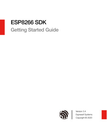
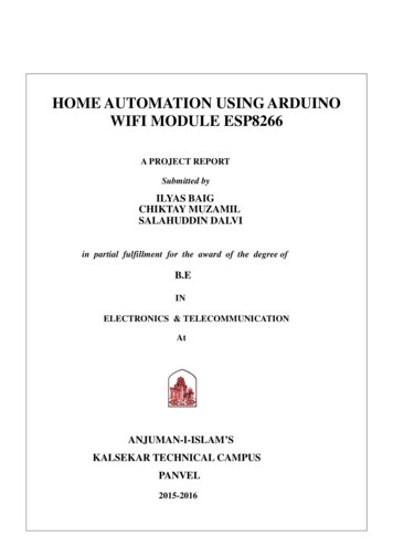
ESP8266 802.11bgn Smart Device1IntroductionEspressif Systems’ Smart Connectivity Platform (ESCP) of high performance wireless SOCs, formobile platform designers, provides unsurpassed ability to embed Wi-Fi capabilities within OCrystal1/2Digital basebandRFreceiveSwitchRF balunsystems, at the lowest cost with the greatest ncersGPIOAcceleratorI2CPLLBias circuitsSRAMPMUFigure 1: ESP8266 Block Diagram4 PageEspressif SystemsOct 12, 2013
ESP8266 802.11bgn Smart Device2Technology OverviewESP8266 offers a complete and self-contained Wi-Fi networking solution, allowing it to eitherhost the application or to offload all Wi-Fi networking functions from another applicationprocessor.When ESP8266 hosts the application, and when it is the only application processor in the device,it is able to boot up directly from an external flash. It has integrated cache to improve theperformance of the system in such applications, and to minimize the memory requirements.Alternately, serving as a Wi-Fi adapter, wireless internet access can be added to anymicrocontroller-based design with simple connectivity through UART interface or the CPUAHB bridge interface.ESP8266 on-board processing and storage capabilities allow it to be integrated with the sensorsand other application specific devices through its GPIOs with minimal development up-front andminimal loading during runtime. With its high degree of on-chip integration, which includes theantenna switch balun, power management converters, it requires minimal external circuitry, andthe entire solution, including front-end module, is designed to occupy minimal PCB area.Sophisticated system-level features include fast sleep/wake context switching for energyefficient VoIP, adaptive radio biasing for low-power operation, advance signal processing, andspur cancellation and radio co-existence features for common cellular, Bluetooth, DDR, LVDS,LCD interference mitigation.5 PageEspressif SystemsOct 12, 2013
ESP8266 802.11bgn Smart Device3Features 802.11 b/g/n protocol Wi-Fi Direct (P2P), soft-AP Integrated TCP/IP protocol stack Integrated TR switch, balun, LNA, power amplifier and matching network Integrated PLL, regulators, and power management units 19.5dBm output power in 802.11b mode Integrated temperature sensor Supports antenna diversity Power down leakage current of 10uA Integrated low power 32-bit CPU could be used as application processor SDIO 2.0, SPI, UART STBC, 1 1 MIMO, 2 1 MIMO A-MPDU & A-MSDU aggregation & 0.4 s guard interval Wake up and transmit packets in 2ms Standby power consumption of 1.0mW (DTIM3)6 PageEspressif SystemsOct 12, 2013
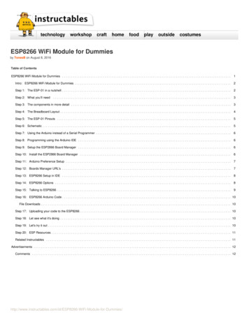
ESP8266 802.11bgn Smart Device4Application Diagram7 PageEspressif SystemsOct 12, 2013
ESP8266 802.11bgn Smart Device5Ultra Low Power TechnologyESP8266 has been designed for mobile, wearable electronics and Internet of Things applicationswith the aim of achieving the lowest power consumption with a combination of severalproprietary techniques. The power saving architecture operates in 3 modes: active mode, sleepmode and deep sleep mode.By using advance power management techniques and logic to power-down functions notrequired and to control switching between sleep and active modes, ESP8266 consumes less than12uA in sleep mode and less than 1.0mW (DTIM 3) or less than 0.5mW (DTIM 10) to stayconnected to the access point.When in sleep mode, only the calibrated real-time clock and watchdog remains active. The realtime clock can be programmed to wake up the ESP8266 at any required interval.The ESP8266 can be programmed to wake up when a specified condition is detected. Thisminimal wake-up time feature of the ESP8266 can be utilized by mobile device SOCs, allowingthem to remain in the low-power standby mode until Wi-Fi is needed.In order to satisfy the power demand of mobile and wearable electronics, ESP8266 can beprogrammed to reduce the output power of the PA to fit various application profiles, by tradingoff range for power consumption.5.1Highest Level of IntegrationBy integrating the costliest components such as power management unit, TR switch, RF balun,high power PA capable of delivering 25dBm (peak), ESP8266 ensures that the BOM cost is thelowest possible, and ease of integration into any system.With ESP8266, the only external BOM are resistors, capacitors, and crystal.8 PageEspressif SystemsOct 12, 2013
ESP8266 802.11bgn Smart Device6ESP8266 Applications Smart power plugs Home automation Mesh network Industrial wireless control Baby monitors IP Cameras Sensor networks Wearable electronics Wi-Fi location-aware devices Security ID tags Wi-Fi position system beacons9 PageEspressif SystemsOct 12, 2013
ESP8266 802.11bgn Smart Device7Specifications7.1Current ConsumptionThe following current consumption is based on 3.3V supply, and 25 C ambient, using internalregulators. Measurements are done at antenna port without SAW filter. All the transmitter’smeasurements are based on 90% duty cycle, continuous transmit mode.ModeMinTypMaxUnitTransmit 802.11b, CCK 1Mbps, POUT 19.5dBm215mATransmit 802.11b, CCK 11Mbps, POUT 18.5dBm197mATransmit 802.11g, OFDM 54Mbps, POUT 16dBm145mATransmit 802.11n, MCS7, POUT 14dBm135mAReceive 802.11b, packet length 1024 byte, -80dBm60mAReceive 802.11g, packet length 1024 byte, -70dBm60mAReceive 802.11n, packet length 1024 byte, -65dBm62mAStandby0.9mADeep sleep10uAPower save mode DTIM 11.2mAPower save mode DTIM 30.86mATotal shutdown0.5uA10 P a g eEspressif SystemsOct 12, 2013
ESP8266 802.11bgn Smart Device7.2RF PerformanceThe following are measured under room temperature conditions with 3.3V and 1.1V powersupplies.DescriptionMinInput frequency2412Input impedanceTypicalMaxUnit2484MHz 50Input reflection-10dBOutput power of PA for 72.2Mbps141516dBmOutput power of PA for 11b mode17.518.519.5dBmSensitivityCCK, 1Mbps-98dBmCCK, 11Mbps-91dBm6Mbps (1/2 BPSK)-93dBm54Mbps (3/4 64-QAM)-75dBmHT20, MCS7 (65Mbps, 72.2Mbps)-71dBmAdjacent Channel Rejection11 P a g eOFDM, 6Mbps37dBOFDM, 54Mbps21dBHT20, MCS037dBHT20, MCS720dBEspressif SystemsOct 12, 2013
ESP8266 802.11bgn Smart Device8CPU, Memory and Interfaces8.1CPUThis chip embeds an ultra low power Micro 32-bit CPU, with 16-bit thumb mode. This CPU canbe interfaced using: code RAM/ROM interface (iBus) that goes to the memory controller, that can also beused to access external flash memory, data RAM interface (dBus), that also goes to the memory controller AHB interface, for register access, and JTAG interface for debugging8.2Memory ControllerThe memory controller contains ROM, and SRAM. It is accessed by the CPU using the iBus,dBus and AHB interface. Any of these interfaces can request access to the ROM or RAMmodules, and the memory controller arbiters serve these 3 interfaces on a first-come-first-servebasis.8.3AHB and AHB BlocksThe AHB blocks performs the function of an arbiter, controls the AHB interfaces from the MAC,SDIO (host) and CPU. Depending on the address, the AHB data requests can go into one of thetwo slaves: APB block, or flash controller (usually for standalone applications).Data requests to the memory controller are usually high speed requests, and requests to the APBblock are usually register access.12 P a g eEspressif SystemsOct 12, 2013
ESP8266 802.11bgn Smart DeviceThe APB block acts as a decoder. It is meant only for access to programmable registers withinESP8266’s main blocks. Depending on the address, the APB request can go to the radio, SI/SPI,SDIO (host), GPIO, UART, real-time clock (RTC), MAC or digital baseband.8.4InterfacesThe ESP8266 contains several analog and digital interfaces described in the following sections.8.4.1Master SI / SPI Control (Optional)The master serial interface (SI) can operate in two, three or four-wire bus configurations tocontrol the EEPROM or other I2C/SPI devices. Multiple I2C devices with different deviceaddresses are supported by sharing the 2-wire bus.Multiple SPI devices are supported by sharing the clock and data signals, using separate softwarecontrolled GPIO pins as chip selects.The SPI can be used for controlling external devices such as serial flash memories, audioCODECs, or other slave devices. It is set up as a standard master SPI device with 3 differentenable pins: SPI EN0, SPI EN1, SPI EN2.Both SPI master and SPI slave are supported with the latter being used as a host interface.SPI EN0 is used as an enable signal to an external serial flash memory for downloading patchcode and/or MIB-data to the baseband in an embedded application. In a host based application,patch code and MIB-data can alternatively be downloaded via the host interface. This pin isactive low and should be left open if not used.SPI EN1 is usually used for a user application, e.g. to control an external audio codec or sensorADC, in an embedded application. This pin is active low and should be left open if not used.13 P a g eEspressif SystemsOct 12, 2013
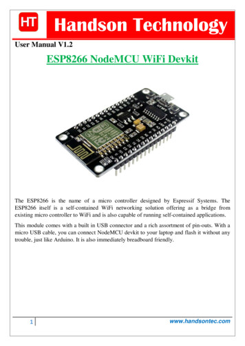
ESP8266 802.11bgn Smart DeviceSPI EN2 usually controls an EEPROM to store individual data, such as MIB information, MACaddress, and calibration data, or for general use. This pin is active low and should be left open ifnot used.Figure 2: SPI timing characteristics8.4.2General Purpose IOThere are up to 16 GPIO pins. They can be assigned to various functions by the firmware. EachGPIO can be configured with internal pull-up/down, input available for sampling by a softwareregister, input triggering an edge or level CPU interrupt, input triggering a level wakeup interrupt,open-drain or push-pull output driver, or output source from a software register, or a sigma-deltaPWM DAC.These pins are multiplexed with other functions such as host interface, UART, SI, Bluetoothcoexistence, etc.8.4.3Digital IO PadsThe digital IO pads are bidirectional, non-inverting and tri-state. It includes input and an outputbuffer with tristate control inputs. Besides this, for low power operations, the IO can also be setto hold. For instance, when we power down the chip, all output enable signals can be set to holdlow.14 P a g eEspressif SystemsOct 12, 2013
ESP8266 802.11bgn Smart DeviceOptional hold functionality can be built into the IO if requested. When the IO is not driven by theinternal or external circuitry, the hold functionality can be used to hold the state to the last usedstate.The hold functionality introduces some positive feedback into the pad. Hence, the external driverthat drives the pad must be stronger than the positive feedback. The required drive strength ishowever small – in the range of 5uA.ParameterSymbolMinMaxUnitInput low voltageVIL-0.30.25 VIOVInput high voltageVIH0.75 VIO3.6VInput leakage currentIIL50nAOutput low voltageVOL0.1 VIOVOutput high voltageVOHInput pin capacitanceCpadVDDIOVIOMaximum drive capabilityIMAXTemperatureTambV0.8 VIO1.7-202pF3.6V12mA100 CAll digital IO pins are protected from over-voltage with a snap-back circuit connected betweenthe pad and ground. The snap back voltage is typically about 6V, and the holding voltage is 5.8V.This provides protection from over-voltages and ESD. The output devices are also protectedfrom reversed voltages with diodes.15 P a g eEspressif SystemsOct 12, 2013
ESP8266 802.11bgn Smart Device9Firmware & Software Development KitThe application and firmware is executed in on-chip ROM and SRAM, which loads theinstructions during wake-up, through the SDIO interface, from the external flash.The firmware implements TCP/IP, the full 802.11 b/g/n/e/i WLAN MAC protocol and Wi-FiDirect specification. It supports not only basic service set (BSS) operations under the distributedcontrol function (DCF) but also P2P group operation compliant with the latest Wi-Fi P2Pprotocol. Low level protocol functions are handled automatically by ESP8266: RTS/CTS, acknowledgement, fragmentation and defragmentation, aggregation, frame encapsulation (802.11h/RFC 1042), automatic beacon monitoring / scanning, and P2P Wi-Fi direct,Passive or active scanning, as well as P2P discovery procedure is performed autonomously onceinitiated by the appropriate command. Power management is handled with minimum hostinteraction to minimize active duty period.9.1FeaturesThe SDK includes the following library functions: 802.11 b/g/n/d/e/i/k/r support; Wi-Fi Direct (P2P) support: P2P Discovery, P2P Group Owner mode, P2P Power Management Infrastructure BSS Station mode / P2P mode / softAP mode support; Hardware accelerators for CCMP (CBC-MAC, counter mode), TKIP (MIC, RC4), WAPI(SMS4), WEP (RC4), CRC;16 P a g eEspressif SystemsOct 12, 2013
ESP8266 802.11bgn Smart Device WPA/WPA2 PSK, and WPS driver; Additional 802.11i security features such as pre-authentication, and TSN; Open Interface for various upper layer authentication schemes over EAP such as TLS,PEAP, LEAP, SIM, AKA, or customer specific; 802.11n support (2.4GHz / 5GHz); Supports MIMO 1 1 and 2 1, STBC, A-MPDU and A-MSDU aggregation and 0.4 sguard interval; WMM power save U-APSD; Multiple queue management to fully utilize traffic prioritization defined by 802.11estandard; UMA compliant and certified; 802.1h/RFC1042 frame encapsulation; Scattered DMA for optimal CPU off load on Zero Copy data transfer operations; Antenna diversity and selection (software managed hardware); Clock/power gating combined with 802.11-compliant power management dynamicallyadapted to curent connection condition providing minimal power consumption; Adaptive rate fallback algorithm sets the optimium transmission rate and Tx power basedon actual SNR and packet loss information; Automatic retransmission and response on MAC to avoid packet discarding on slow hostenvironment; Seamless roaming support; Configurable packet traffic arbitration (PTA) with dedicated slave processor based designprovides flexible and exact timing Bluetooth co-existence supoport for a wide range ofBluetooth Chip vendors; Dual and single antenna Bluetooth co-existence support with optional simultaneousreceive (Wi-Fi/Bluetooth) capability.17 P a g eEspressif SystemsOct 12, 2013
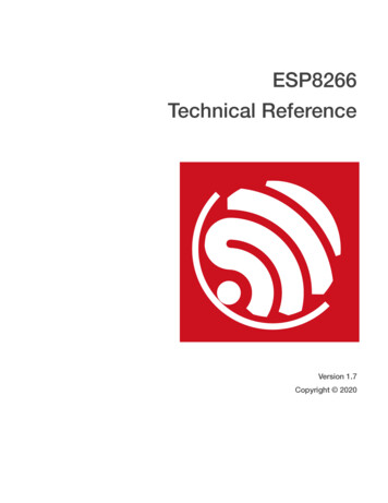
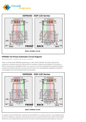
ESP8266 802.11bgn Smart Device10 Power ManagementThe chip can be put into the following states: OFF: CHIP PD pin is low. The RTC isCHIP PWDdisabled. All registers are cleared. OffDEEP SLEEP: Only RTC is powered on –the rest of the chip is powered off. CHIP PWDRecovery memory of RTC can keep basicDeep SleepWi-Fi connecting information. SLEEP: Only the RTC is operating. Thecrystal oscillator is disabled. Any wakeupSleepXTAL Offevents (MAC, host, RTC timer, externalWAKEUPeventsinterrupts) will put the chip into theWAKEUP state. SLEEP criteriaWAKEUP: In this state, the system goesWakeupXTAL SETTLEfrom the sleep states to the PWR state. Thecrystal oscillator and PLLs are enabled. OnON state: the high speed clock isoperational and sent to each block enabled by the clock control register. Lower levelclock gating is implemented at the block level, including the CPU, which can be gated offusing the WAITI instruction, while the system is on.18 P a g eEspressif SystemsOct 12, 2013
ESP8266 802.11bgn Smart Device11 Clock Management11.1High Frequency ClockThe high frequency clock on ESP8266 is used to drive both the Tx and Rx mixers. This clock isgenerated from the internal crystal oscillator and an external crystal. The crystal frequency canrange from 26MHz to 52MHz.While internal calibration of the crystal oscillator ensures that a wide range of crystals can beused, in general, the quality of the crystal is still a factor to consider, to obtain reasonable phasenoise. When the crystal selected is sub-optimal due to large frequency drifts or poor Q-factor, themaximum throughput and sensitivity of the Wi-Fi system is degraded. Please refer to theapplication notes on how the frequency offset can be measured.19 P a g ng capacitanceCL32pFMotional capacitanceCM25pFSeries resistanceRS065 Frequency tolerance FXO-1515ppmFrequency vs temperature (-25 C 75 C) FXO,Temp-1515ppmEspressif SystemsOct 12, 2013
ESP8266 802.11bgn Smart Device11.2External Reference RequirementsFor an externally generated clock, the frequency can range from 26MHz to 52MHz can be used.For good performance of the radio, the following characteristics are expected of the clock:ParameterSymbolMinMaxUnitClock amplitudeVXO0.21VppExternal clock accuracy FXO,EXT-1515ppmPhase noise @1kHz offset, 40MHz clock-120dBc/HzPhase noise @10kHz offset, 40MHz clock-130dBc/HzPhase noise @100kHz offset, 40MHz clock-138dBc/Hz20 P a g eEspressif SystemsOct 12, 2013
ESP8266 802.11bgn Smart Device12 RadioThe ESP8266 radio consists of the following main blocks: 2.4GHz receiver 2.4GHz transmitter High speed clock generators and crystal oscillator Real time clock Bias and regulators Power management12.1Channel FrequenciesThe RF transceiver supports the following channels according to the IEEE802.11bgn 625243212246762437132472724421424842.4GHz ReceiverThe 2.4GHz receiver downconverts the RF signal to quadrature baseband signals and convertsthem to the digital domain with 2 high resolution high speed ADCs. To adapt to varying signalchannel conditions, RF filters, automatic gain control, DC offset cancelation circuits andbaseband filters are integrated within the radio.21 P a g eEspressif SystemsOct 12, 2013
ESP8266 802.11bgn Smart Device12.32.4GHz TransmitterThe 2.4GHz transmitter upconverts the quadrature baseband signals to 2.4GHz, and drives theantenna with a high powered CMOS power amplifier. The use of digital calibration furtherimproves the linearity of the power amplifier, enabling a state of art performance of delivering 19dBm average power for 802.11b transmission and 16dBm for 802.11n transmission.Additional calibrations are integrated to cancel any imperfections of the radio, such as: carrier leakage, I/Q phase matching, and baseband nonlinearitiesThis reduces the amount of time required and test equipment required for production testing.12.4Clock GeneratorThe clock generator generates quadrature 2.4GHz clock signals for the receiver and transmitter.All components of the clock generator are integrated on-chip, including: inductor, varactor, and loop filter.The clock generator has built-in calibration and self test circuits. Quadrature clock phases andphase noise are optimized on-chip with patented calibration algorithms to ensure the bestreceiver and transmitter performance.22 P a g eEspressif SystemsOct 12, 2013
ESP8266 802.11bgn Smart DeviceApp.QFN32 Package Drawing23 P a g eEspressif SystemsOct 12, 2013
mobile platform designers, provides unsurpassed ability to embed Wi-Fi capabilities within other systems, at the lowest cost with the greatest functionality. . and the memory controller arbiters serve these 3 interfaces on a first-come-first-serve basis. 8.3 AHB and AHB Blocks The AHB blocks performs the function of an arbiter, controls the .