Transcription
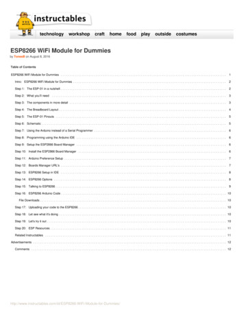
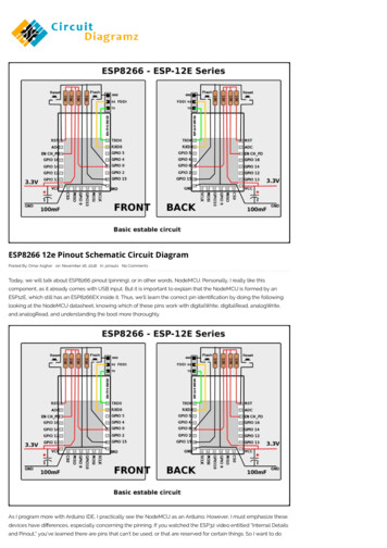
11/27/2018ESP8266 12e Pinout Schematic Circuit Diagram- NodeMCUESP8266 12e Pinout Schematic Circuit DiagramPosted By: Omar Asghar on: November 26, 2018 In: pinouts No CommentsToday, we will talk about ESP8266 pinout (pinning), or in other words, NodeMCU. Personally, I really like thiscomponent, as it already comes with USB input. But it is important to explain that the NodeMCU is formed by anESP12E, which still has an ESP8266EX inside it. Thus, we’ll learn the correct pin identi cation by doing the following:looking at the NodeMCU datasheet, knowing which of these pins work with digitalWrite, digitalRead, analogWrite,and analogRead, and understanding the boot more thoroughly.As I program more with Arduino IDE, I practically see the NodeMCU as an Arduino. However, I must emphasize thesedevices have di erences, especially concerning the pinning. If you watched the ESP32 video entitled “Internal -pinout-schematic-circuit-diagram/Pinout,” you’ve learned there are pins that can’t be used, or that are reserved for certain things. So I want to do1/8
11/27/2018ESP8266 12e Pinout Schematic Circuit Diagram- NodeMCUsomethinguseful here related to this, but this time with ESP8266.Step 1: NodeMCU Devkit 1.0The term NodeMCU usually refers to the rmware, while the board is called Devkit. NodeMCU Devkit 1.0 consists ofan ESP-12E on a board, which facilitates its use. It also has a voltage regulator, a USB interface.Step 2: ESP-12EThe ESP-12E is a board created by AI-THINKER, which consists of an ESP8266EX inside the metal cover.Step 3: pinout-schematic-circuit-diagram/2/8
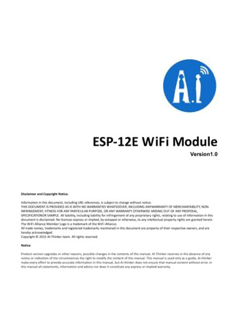
11/27/2018ESP8266 12e Pinout Schematic Circuit Diagram- NodeMCUMade by Espressif, this microchip has integrated WiFi and low-power consumption. Processor RISC Tensilica L 10632bit with a maximum clock of 160 MHz.Step 4: NodeMCU 1.0 ESP-12E PinoutStep 5: ESP-12E out-schematic-circuit-diagram/3/8
11/27/2018ESP8266 12e Pinout Schematic Circuit Diagram- NodeMCUI want to emphasize that NodeMCU and ESP-12E are not the same things. In the case of the ESP-12E, the recordinguses the serial, the UART. In NodeMCU, this is performed by the USB.Step 6: And After All This, What’s the Number to Put When Programming?Use the number that is in front of the GPIO or the constants A0, D0, D1, D2, D3, D4, D5, D6, D7, and D8.Step 7: t-schematic-circuit-diagram/4/8
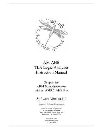
11/27/2018ESP8266 12e Pinout Schematic Circuit Diagram- NodeMCUWe put the oscilloscope at the tip of each pin. This allows us to nd, for example, that when we turn on theNodeMCU, its pins are not all the same. Some are up and others down, by default. See the comments on thebehavior of each post after the boot in the image below.Step 8: Constants That Are Already PredefinedStep 9: Blink nout-schematic-circuit-diagram/5/8
11/27/2018ESP8266 12e Pinout Schematic Circuit Diagram- NodeMCUIn this example, we connected an LED on port D5, which is GPIO14. So the options are as follows://O led está no GPIO14#de ne LED 6//ou usar a constante D5 que já está de nida//#de ne LED D5void setup() {pinMode(LED, FUNCTION 3);}void loop() {digitalWrite(LED, HIGH);delay(1000);digitalWrite(LED, LOW);delay(1000);}Step 10: INPUT / OUTPUTWhen performing INPUT and OUTPUT tests on the pins, we obtained the following results:digitalWrite did NOT work with GPIOs 6, 7, 8, 11, and ADC (A0)digitalRead did NOT work with GPIOs 1, 3, 6, 7, 8, 11, and the ADC (A0)analogWrite did NOT work with GPIOs 6, 7, 8, 11, and ADC (A0) (GPIOs 4, 12, 14, 15 have hardware PWM, and theothers are by software)analogRead worked only with the ADC (A0)6, 7, 8, 11 do NOT work for the above four inout-schematic-circuit-diagram/6/8
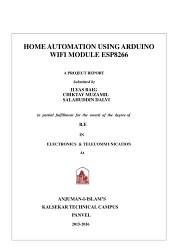
11/27/2018NodeMCUPinout ReferenceESP8266 12e Pinout Schematic Circuit Diagram- NodeMCUThe NodeMCU is an Arduino-compatible board that features the ESP8266 at its core. It became popular because it isa WiFi-ready microcontroller by itself – no need for an Arduino.NodeMCU V0.9This is the rst version of the NodeMCU board featuring the ESP-12. The V0.9 board has since been outdatedprimarily because of its width that isn’t breadboard friendly. The number of Not Connected (NC) pins is also a reason.NodeMCU V1.0The second generation of the NodeMCU is arguably the most popular one. Amica (the company that created both V0.9and V1.0) made this board narrower to fit a breadboard. Moreover, the ESP8266 has also been upgraded from ESP-12 toESP-12E (a few extra pins).NodeMCU schematic-circuit-diagram/7/8
11/27/2018ESP8266 12e Pinout Schematic Circuit Diagram- NodeMCUThis is a version invented by Lolin with a CH340G USB-TTL chip instead of the Silabs CP2102 from V1.0. As shown, ithas the same pinout structure with V1.0. But this board is slightly larger than the t-schematic-circuit-diagram/8/8
The NodeMCU is an Arduino-compatible board that features the ESP8266 at its core. It became popular because it is a WiFi-ready microcontroller by itself - no need for an Arduino. NodeMCU V0.9 This is the rst version of the NodeMCU board featuring the ESP-12. The V0.9 board has since been outdated