Transcription
HP ProLiant DL580 Generation 5 ServerUser GuidePart Number 453878-002September 2008 (Second Edition)
Copyright 2007 Hewlett-Packard Development Company, L.P.The information contained herein is subject to change without notice. The only warranties for HP products and services are set forth in the expresswarranty statements accompanying such products and services. Nothing herein should be construed as constituting an additional warranty. HPshall not be liable for technical or editorial errors or omissions contained herein.Microsoft, Windows, Windows Server 2003, and Windows NT are U.S. registered trademarks of Microsoft Corporation.Intended audienceThis document is for the person who installs, administers, and troubleshoots servers and storage systems.HP assumes you are qualified in the servicing of computer equipment and trained in recognizing hazardsin products with hazardous energy levels.
ContentsComponent identification . 7Front panel components . 7Front panel LEDs and buttons . 8Systems Insight Display . 9Rear panel components. 10Rear panel LEDs and buttons. 11Power supply LED. 12System board components. 13SPI board components . 14System maintenance switch. 14FBDIMM slot locations . 15SAS device numbers . 16SAS hard drive LEDs . 17SAS hard drive LED combinations. 17Battery pack LEDs. 18Fan locations . 20Operations. 21Power up the server . 21Power down the server. 21Extending the server from the rack . 21Removing the access panel. 23Accessing the Systems Insight Display . 24Removing the system battery . 24Setup. 26Optional installation services . 26Rack planning resources. 26Optimum environment. 27Space and airflow requirements . 27Temperature requirements. 27Power requirements . 28Electrical grounding requirements . 28Rack warnings . 29Identifying the contents of the server shipping carton. 29Installing hardware options. 29Setting up a tower model server . 30Installing the server into the rack. 31Powering up and configuring the server . 31Installing the operating system. 32Registering the server. 32Hardware options installation. 33Introduction . 33Processor options . 33Removing the processor memory module . 33Installing a processor . 35Contents3
Memory options . 39Memory configurations. 39Advanced ECC memory . 40Online spare memory configuration . 41Mirrored memory configuration . 42Installing FBDIMMs . 42Installing optional memory expansion boards. 43Hot-plug SAS hard drive options . 44Installing a hot-plug SAS hard drive . 44Installing the drive cage . 45Tape drive. 49Redundant hot-plug power supply option . 52Battery-backed write cache . 53Fans . 56Expansion board options. 57Installing non-hot-plug expansion boards . 57Installing the PCI Express x8 3 Slot Option Card . 58Installing the PCI-X 3 Slot Option Card . 59Cabling . 61BBWC cabling. 61Hard drive cabling . 62Tape drive cabling . 63SATA DVD drive cabling . 63DVD drive cabling. 63Server software and configuration utilities. 65Configuration tools . 65SmartStart software. 65SmartStart Scripting Toolkit . 65HP ROM-Based Setup Utility . 66Using RBSU . 66Configuring online spare memory. 66Configuring mirrored memory . 67Auto-configuration process. 67Boot options . 68BIOS Serial Console . 68HP ProLiant Essentials Rapid Deployment Pack . 68Option ROM Configuration for Arrays . 68Array Configuration Utility. 69Re-entering the server serial number and product ID. 69Management tools. 70Automatic Server Recovery . 70ROMPaq utility. 70System Online ROM flash component utility . 70Remote Insight Lights-Out Edition II . 70Integrated Lights-Out 2 technology . 71StorageWorks library and tape tools. 71HP Systems Insight Manager . 71Management Agents. 71Redundant ROM support . 72USB support. 72Diagnostic tools . 72HP Insight Diagnostics . 72Contents4
Integrated Management Log . 73Array Diagnostic Utility . 73Remote support and analysis tools . 73HP Instant Support Enterprise Edition. 73Keeping the system current . 74Drivers . 74ProLiant Support Packs . 74Operating system version support . 74Change control and proactive notification . 74Care Pack . 74Troubleshooting . 75Troubleshooting resources . 75Pre-diagnostic steps . 75Important safety information. 75Symptom information . 77Prepare the server for diagnosis . 78Loose connections . 78Service notifications. 79Troubleshooting flowcharts . 79Start diagnosis flowchart . 79General diagnosis flowchart . 80Server power-on problems flowchart . 82POST problems flowchart . 85OS boot problems flowchart . 86Server fault indications flowchart . 88POST error messages and beep codes . 90Regulatory compliance notices . 91Regulatory compliance identification numbers . 91Federal Communications Commission notice. 91FCC rating label. 91Class A equipment. 91Class B equipment . 91Declaration of conformity for products marked with the FCC logo, United States only. 92Modifications. 92Cables . 92Canadian notice (Avis Canadien). 93European Union regulatory notice . 93Disposal of waste equipment by users in private households in the European Union . 93Japanese notice . 94BSMI notice . 94Korean notice . 94Laser compliance . 95Battery replacement notice. 95Taiwan battery recycling notice. 96Power cord statement for Japan. 96Acoustics statement for Germany (Geräuschemission) . 96Electrostatic discharge . 97Preventing electrostatic discharge . 97Grounding methods to prevent electrostatic discharge . 97Specifications . 98Environmental specifications . 98Contents5
Server specifications . 98Technical support. 100Before you contact HP. 100HP contact information . 100Acronyms and abbreviations. 101Index. 105Contents6
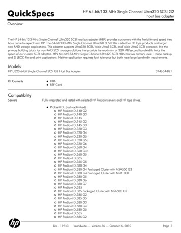
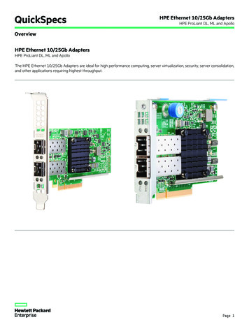
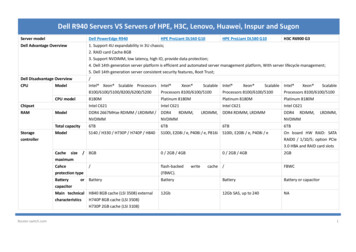
Component identificationFront panel componentsItemDescription1USB connectors2Video connector3Systems Insight Display4DVD drive bay5Optional tape drive or blank6Optional hard drive bay or blank7Hard drive bay8Processor memory moduleComponent identification 7
Front panel LEDs and buttonsItemDescriptionStatus1UID switch and LEDBlue—ActivatedBlue (flashing)—Server being managed remotelyOff—Deactivated2Internal system health LEDGreen—Normal (system on)Amber (flashing)—Internal system health degradedRed (flashing)—Internal system health criticalOff—Normal (system off)3External system health LEDGreen—Normal (system on)Amber (flashing)—External system health degradedRed (flashing)—External system health criticalOff—Normal (system off)4NIC 1 link/activity LEDGreen—Linked to networkGreen (flashing)—Linked with activity on the networkOff—No network connection5NIC 2 link/activity LEDGreen—Linked to networkGreen (flashing)—Linked with activity on the networkOff—No network connection6Power on/Standby button andLEDAmber—System has AC power and is in standby mode.Green—System has AC power and is turned on.Off—System has no AC power.Component identification 8
Systems Insight DisplayThe Systems Insight Display LEDs represent the server and component layout.LEDDescriptionONLINE SPAREOff—No protectionGreen—Protection enabledAmber—Memory failure occurredAmber (flashing)—Memory configuration errorMIRROROff—No protectionGreen—Protection enabledAmber—Memory failure occurredAmber (flashing)—Memory configuration errorAll other LEDsOff—NormalAmber—Failed or missing componentComponent identification 9
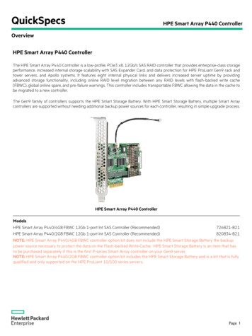
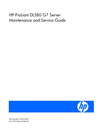
Rear panel componentsItemDescriptionItemDescription1Power supply bay 4 (optional)13PCI-X non-hot-plug for PCI Express x8 non-hotplug expansion slot 3 (optional)2Power supply bay 3 (optional)14PCI Express x8 non-hot-plug expansion slot 43Power supply bay 215PCI Express x8 non-hot-plug expansion slot 54Power supply bay 116PCI Express x8 non-hot-plug expansion slot 65Keyboard connector17PCI Express x8 non-hot-plug expansion slot 76USB connectors18PCI Express x4 non-hot-plug expansion slot 87Video connector19PCI Express x4 non-hot-plug expansion slot 98Serial connector20PCI Express x4 non-hot-plug expansion slot109iLO 2 NIC connector21PCI Express x4 non-hot-plug expansion slot1110Mouse connector22NIC 2 connector11PCI-X non-hot-plug or PCI Express x8non-hot-plug expansion slot 1(optional)23NIC 1 connector12PCI-X non-hot-plug or PCI Express x8non-hot-plug expansion slot 2(optional)24Torx T-15 toolComponent identification 10
Rear panel LEDs and buttonsItemDescriptionLED colorStatus1NIC 2 Activity LEDGreenOn or flashing—Network activityOff—No network activity2NIC 2 Link LEDGreenOn—Linked to networkOff—Not linked to network3UIDBlueOn—Front UID button activatedOff—Normal4iLO 2 NIC Activity LEDGreenOn or flashing—Network activityOff—No network activity5iLO 2 NIC Link LEDGreenOn—Linked to networkOff—Not linked to network6NIC 1 Link LEDGreenOn—Linked to networkOff—Not linked to network7NIC 1 Activity LEDGreenOn or flashing—Network activityOff—No network activityComponent identification 11
Power supply LEDPower LED(green)Failure LED(amber)StatusOffOffNo AC power to power supply unitsOnOffAC present. Standby output on. Power supply DC output on and OKOffOnPower supply failure (includes overvoltage and overtemperature)Component identification 12
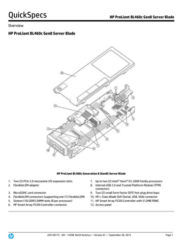
System board componentsItemDescription1Fan 12Fan 23Connector for: PCI Express x8 3 Slot Option Card (optional) PCI-X 3 Slot Option Card (optional)4Fan 35Fan 56Fan 47Fan 68PCI Express x8 non-hot-plug expansion slot 49PCI Express x8 non-hot-plug expansion slot 510PCI Express x8 non-hot-plug expansion slot 611PCI Express x8 non-hot-plug expansion slot 712PCI Express x4 non-hot-plug expansion slot 813PCI Express x4 non-hot-plug expansion slot 914PCI Express x4 non-hot-plug expansion slot 1015PCI Express x4 non-hot-plug expansion slot 11Component identification 13
ItemDescription16System maintenance switch17SPI boardSPI board componentsItemDescription1BBWC cache module connectors2BatterySystem maintenance switchThe system maintenance switch (SW1) is an eight-position switch that is used for system configuration. Thedefault position for all eight positions is Off.PositionDescriptionFunctionS1iLO 2 SecurityOff iLO 2 security is enabledOn iLO 2 security is disabledS2ConfigurationlockOff System configuration canbe changedOn System configuration wordprotectionoverrideOff No functionOn Clears power-onpassword and administratorpasswordComponent identification 14
onOff NormalS7ReservedReservedS8ReservedReservedOn Clears NVRAMFBDIMM slot locationsThe server contains 16 FBDIMM slots on the processor-memory board, which are numbered sequentiallyfrom 1 to 16. The paired banks are identified by the letters A through H.Four FBDIMM slots located on each optional memory board are numbered from 1 to 4. The paired banksare identified by the letters A through D.Component identification 15
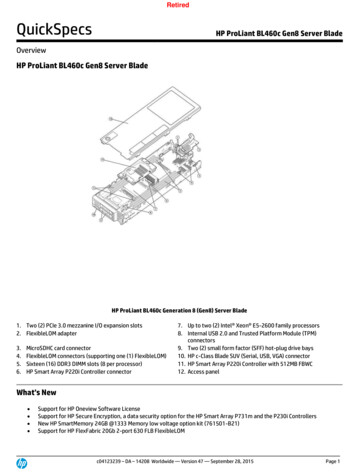
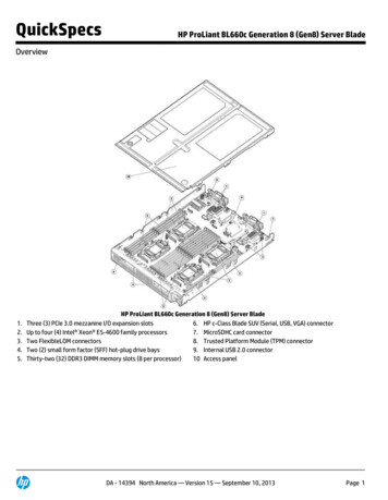
SAS device numbersComponent identification 16
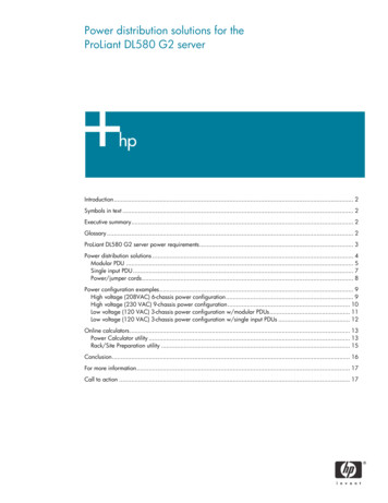
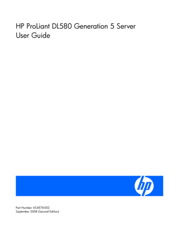
SAS hard drive LEDsItemDescription1Fault/UID LED (amber/blue)2Online LED (green)SAS hard drive LED combinationsOnline/activityLED (green)Fault/UID LED(amber/blue)On, off, orflashingAlternating amber and The drive has failed, or a predictive failure alert has beenbluereceived for this drive; it also has been selected by amanagement application.On, off, orflashingSteadily blueThe drive is operating normally, and it has been selected by amanagement application.OnAmber, flashingregularly (1 Hz)A predictive failure alert has been received for this drive.Replace the drive as soon as possible.OffThe drive is online, but it is not active currently.OnFlashing regularly Amber, flashing(1 Hz)regularly (1 Hz)InterpretationDo not remove the drive. Removing a drive may terminate thecurrent operation and cause data loss.The drive is part of an array that is undergoing capacityexpansion or stripe migration, but a predictive failure alert hasbeen received for this drive. To minimize the risk of data loss,do not replace the drive until the expansion or migration iscomplete.Flashing regularly Off(1 Hz)Do not remove the drive. Removing a drive may terminate thecurrent operation and cause data loss.The drive is rebuilding, or it is part of an array that isundergoing capacity expansion or stripe migration.FlashingirregularlyAmber, flashingregularly (1 Hz)The drive is active, but a predictive failure alert has beenreceived for this drive. Replace the drive as soon as possible.Component identification 17
Online/activityLED (green)Fault/UID fThe drive is active, and it is operating normally.OffSteadily amberA critical fault condition has been identified for this drive, andthe controller has placed it offline. Replace the drive as soon aspossible.OffAmber, flashingregularly (1 Hz)A predictive failure alert has been receive
SAS hard drive LEDs Item Description 1 Fault/UID LED (amber/blue) 2 Online LED (green) SAS hard drive LED combinations Online/activity LED (green) Fault/UID LED (amber/blue) Interpretation On, off, or flashing Alternating amber and blue The drive has failed, or a predictive failure alert has been