Transcription
ESP8266Technical ReferenceVersion 1.7Copyright 2020
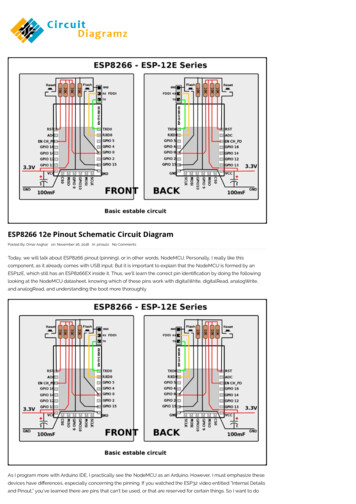
About This GuideThis document provides introduction to the interfaces integrated on ESP8266. Functionaloverview, parameter configuration, function description, application demos and otherinformation is included.The document is structured as below.ChapterTitleSubjectChapter 1OverviewOverall introduction to the interfaces.Chapter 2GPIODescription of GPIO functions, registers and parameterconfiguration.Chapter 3SPI Compatibility ModeUser GuideDescription of functions, DEMO solution, ESP8266 softwareinstruction and STM32 software solution.Chapter 4SPI Communication UserGuideDescription of SPI functions, master/slave protocol format and APIfunctions.Chapter 5SPI Overlap & DisplayApplication GuideDescription of SPI functions, hardware connection of SPI overlapmode, API description and display screen console program demo.Chapter 6SPI Wi-Fi Passthrough 1Interrupt ModeDescription of SPI functions, SPI slave protocol format, slave statusand line breakage and API functions.Chapter 7SPI Wi-Fi Passthrough 2Interrupt ModeDescription of SPI functions, SPI slave protocol format, data flowcontrol line and API functions.Chapter 8HSPI Host Multi-deviceAPIDescription of HSPI functions, hardware connection and APIfunctions.Chapter 9I2C User GuideDescription of I2C functions, master interface and demo.Chapter 10I2S Module DescriptionDescription of I2S functions, system configuration and APIfunctions.Chapter 11UART IntroductionDescription of UART functions, hardware resources, parameterconfiguration, interrupt configuration, example of interrupt handlerprocess and abandon serial output during booting.Chapter 12PWM InterfaceDescription of PWM functions PWM, detailed on pwm.h, andcustom channels.Chapter 13IR Remote Control UserGuideIntroduction on infrared transmission, parameter configuration andfunctions of sample codes.Chapter 14Sniffer IntroductionIntroduction on Sniffer, application scenarios, phone App and IOTdevice firmware.AppendixAppendixGPIO registers, SPI registers, UART registers, Timer registers.Release NotesDate2016.05VersionV1.0Release notesFirst release.
DateVersionRelease notes2016.06V1.1Added Section 4.5 Interface Description.2016.08V1.2Updated Section 14.1 Sniffer Introduction.2017.05V1.3Updated Section 4.1.2 SPI Features.2019.08V1.4Updated Section 1.1 General Purpose Input/Output Interface(GPIO).2020.07 Updated Section 1.3 Serial Peripheral Interface (SPI/HSPI); Added documentation feedback links.V1.5 Updated Section 3.3.2 Instructions on The Read/Write2020.08V1.6Buffer and The Registration Linked List; Updated Section 10.2.2 Link List Configuration.2020.10V1.7 Deleted the ESP8266 Pin List in Section 2.1; Deleted the SPI description note in Section 4.5.2.
Table of Contents1. Overview .11.1. General Purpose Input/Output Interface (GPIO) .11.2. Secure Digital Input/Output Interface (SDIO) .11.3. Serial Peripheral Interface (SPI/HSPI) .11.3.1.General SPI (Master/Slave) .21.3.2.HSPI (Master/Slave) .21.4. I2C Interface .21.5. I2S Interface .31.6. Universal Asynchronous Receiver Transmitter (UART) . 31.7. Pulse-Width Modulation (PWM) .41.8. IR Remote Control.41.9. Sniffer .52. GPIO .62.1. Functional Overview.62.2. Instruction on GPIO Registers .72.2.1.GPIO Function Selection Register . 72.2.2.GPIO Output Registers . 72.2.3.GPIO Input Register .82.2.4.GPIO Interrupt Registers .82.2.5.GPIO16 Related APIs .92.3. Parameter onfiguration .92.3.1.Parameter Configuration for Scene 1 .92.3.2.Parameter Configuration for Scene 2 .102.3.3.Parameter Configuration for Scene 3 .112.3.4.Interrupt Function Processing Procedures .112.3.5.Example of The Interrupt Function Processing Procedures .123. SPI Compatibility Mode User Guide. 133.1. Functional Overview.133.2. DEMO Solution .133.2.1.Introduction. 133.2.2.ESP8266 Software Compiling and Downloading .133.2.3.ESP8266 FLASH Software Downloading .14
3.2.4.ESP8266 FLASH Software Downloading .143.3. ESP8266 Software Instruction .153.3.1.Protocol Principle: SDIO Line Breakage and SDIO Status Register.153.3.2.Instructions on The Read/Write Buffer and The Registration Linked List .163.3.3.API Functions in The ESP8266 DEMO .173.4. STM32 Software Instruction .183.4.1.Important functions.184. SPI Communication User Guide. 214.1. Overview .214.1.1.Functional Overview .214.1.2.SPI Features . 214.2. ESP8266 SPI Master Protocol Format .214.2.1.Communication Format Supported by Master SPI .214.2.2.Master SPI Communication Format Supported by Current API .224.3. ESP8266 SPI Slave Protocol Format .224.3.1.SPI Slave Clock Polarity Configuration Requirement .224.3.2.Communication Format Supported by Slave SPI .224.3.3.Command Definition Supported by Slave SPI. 224.3.4.Slave SPI Communication Format Supported by Current API .234.4. API Function Description of SPI Module.234.4.1.API Function Description of Master SPI .234.4.2.Master SPI API Function Description .254.5. SPI Interface Description .274.5.1.Data Structure .274.5.2.API Description .304.5.3.SPI Test Demo .355. SPI Overlap & Display Application Guide .465.1. Functional Overview.465.2. Hardware Connection of SPI Overlap Mode .475.3. API Description of SPI Overlap Mode .475.4. Display Screen Console Program DEMO.485.4.1.Connection Description . 485.4.2.API Function Description .485.4.3.Pre-compiled Macro Setting .506. SPI Wi-Fi Passthrough 1-Interrupt Mode .51
6.1. Functional Overview.516.2. ESP8266 SPI Slave Protocol Format .516.2.1.SPI Slave Clock Polarity Configuration .516.2.2.Communication Format Supported by The SPI Slave.516.3. Slave Status Definition and Line Breakage .526.3.1.Status Definition .526.3.2.GPIO0 Line Breakage .526.4. ESP8266 SPI Slave API Functions .527. SPI Wi-Fi Passthrough 2-Interrupt Mode .587.1. Functional Overview.587.2. ESP8266 SPI Slave Protocol Format .587.2.1.SPI Slave Clock Polarity Configuration .587.2.2.Communication Format Supported by The SPI Slave.587.3. Instruction on The Data Flow Control Line.597.3.1.GPIO0 MOSI Buffer Status .597.3.2.GPIO2 Master Receives The Slave Send Buffer Status .597.3.3.Master Communication Logic Implementation. 597.4. ESP8266 SPI Slave API Functions .618. HSPI Host Multi-device API .648.1. Functional Overview.648.2. Hardware Connection .648.3. API Description .659. I2C User Guide . 679.1. Functional Overview.679.2. I2C master Interface.679.2.1.Initialization . 679.2.2.Start I2C .679.2.3.Stop I2C .689.2.4.I2C Master Responds ACK .689.2.5.I2C Master Responds NACK .689.2.6.Check I2C Slave Response .699.2.7.Write Data on I2C Bus .699.2.8.Read Data from I2C Bus .699.3. Demo .69
10.I2S Module Description .7110.1. Functional Overview.7110.2. System Configuration. 7110.2.1. I2S Module Configuration .7110.2.2. Link List Configuration .7410.2.3. SLC Module Configuration .7510.3. API Function Description .7510.3.1. Void Function .7610.3.2. CONF Function .7610.3.3. START Function .7711.UART Introduction . 7811.1. Functional Overview.7811.2. Hardware Resources .7911.3. Parameter Configuration .7911.3.1. The Baud Rate .7911.3.2. Parity Bit .8011.3.3. Data Bit .8011.3.4. Stop Bit .8011.3.5. Inverting .8011.3.6. Switch Output Port of Print Function .8111.3.7. Read The Remaining Number of Bytes in tx / rx Queue.8111.3.8. Loopback Operation (loop-back).8111.3.9. Line Stop Signal .8111.3.10.Flow Control . 8111.3.11.Other Interfaces .8211.4. Configure Interrupt .8211.4.1. Interrupt register .8211.4.2. Interface .8311.4.3. Interrupt Type .8311.5. Example of Interrupt Handler Process .8711.6. Abandon Serial Output During Booting .8712.PWM Interface . 8912.1. Functional Overview.8912.1.1. Features .8912.1.2. Implementation .89
12.1.3. Configuration .9012.1.4. Parameter Specification .9012.2. Details on pwm.h .9012.2.1. Sample Codes .9012.2.2. Interface Specifications . 9112.3. Custom Channels.9313.IR Remote Control User Guide .9513.1. Introduction to Infrared Transmission .9513.1.1. Transmitting . 9513.1.2. Receiving .9513.2. Parameters Configuration .9613.3. Functions of Infrared Sample Codes .9714.Sniffer Introduction .9814.1. Sniffer Introduction.9814.2. Sniffer Application Scenarios .10114.3. Phone APP .10314.4. IOT-device Firmware .103Appendix .104
1. Overview!1.Overview1.1. General Purpose Input/Output Interface (GPIO)ESP8266EX has 17 GPIO pins which can be assigned to various functions by programmingthe appropriate registers.Each GPIO can be configured with internal pull-up or pull-down, or set to high impedance,and when configured as an input, the data are stored in software registers; the input canalso be set to edge-trigger or level trigger CPU interrupts. In short, the IO pads are bidirectional, non-inverting and tristate, which includes input and output buffer with tristatecontrol inputs.These pins can be multiplexed with other functions such as I2C, I2S, UART, PWM, IRRemote Control, etc.1.2. Secure Digital Input/Output Interface (SDIO)ESP8266EX has one Slave SDIO, the definitions of which are described below. 4-bit 25MHz SDIO v1.1 and 4-bit 50 MHz SDIO v2.0 are supported.Table 1-1: Pin Definitions of SDIOsPin NamePin NumIOFunction NameSDIO CLK21IO6SDIO CLKSDIO DATA022IO7SDIO DATA0SDIO DATA123IO8SDIO DATA1SDIO DATA 218IO9SDIO DATA 2SDIO DATA 319IO10SDIO DATA 3SDIO CMD20IO11SDIO CMD1.3. Serial Peripheral Interface (SPI/HSPI)ESP8266EX has 3 SPIs.One general Slave/Master SPIOne Slave SDIO/SPIOne general Slave/Master HSPIFunctions of all these pins can be implemented via hardware. The pin definitions aredescribed as below.Espressif!1/104Submit Documentation Feedback2020.10
1. Overview!1.3.1. General SPI (Master/Slave)Table 1-2. Pin Definitions of SPIsPin NamePin NumIOFunction NameSDIO CLK21IO6SPICLKSDIO DATA022IO7SPIQ/MISOSDIO DATA123IO8SPID/MOSISDIO DATA 218IO9SPIHDSDIO DATA 319IO10SPIWPU0TXD26IO1SPICS1GPIO015IO0SPICS2 Note:SPI mode can be implemented via software programming. The clock frequency is 80 MHz at maximum.1.3.2. HSPI (Master/Slave)Table 1-3. Pin Definitions of HSPIPin NamePin NumIOFunction HSPID/MOSIMTDO13IO15HPSICS1.4. I2C InterfaceESP8266EX has one I2C used to connect with micro-controller and other peripheralequipments such as sensors. The pin definition of I2C is as below.Table 1-4. Pin Definitions of I2CPin NamePin NumIOFunction NameMTMS9IO14I2C SCLGPIO214IO2I2C SDABoth I2C Master and I2C Slave are supported. I2C interface functionality can be realized viasoftware programming, the clock frequency reaches 100 kHz at a maximum. It should benoted that I2C clock frequency should be higher than the slowest clock frequency of theslave device.Espressif!2/104Submit Documentation Feedback2020.10
1. Overview!1.5. I2S InterfaceESP8266EX has one I2S data input interface and one I2S data output interface. I2Sinterfaces are mainly used in applications such as data collection, processing, andtransmission of audio data, as well as the input and output of serial data. For example, LEDlights (WS2812 series) are supported. The pin definition of I2S is as below. I2S functionalitycan be enabled via software programming by using multiplexed GPIOs, and linked list DMAis supported.Table 1-5. Pin Definitions of I2SI2S Data InputPin NamePin NumIOFunction NameMTDI10IO12I2SI DATAMTCK12IO13I2SI BCKMTMS9IO14I2SI WSMTDO13IO15I2SO BCKU0RXD25IO3I2SO DATAGPIO214IO2I2SO WS1.6. Universal Asynchronous Receiver Transmitter (UART)ESP8266EX has two UART interfaces UART0 and UART, the definitions are as below.Table 1-6. Pin Definitions of UARTPin TypeUART0UART1Pin NamePin NumIOFunction TCK12IO13U0CTSGPIO214IO2U1TXDSD D123IO8U1RXDData transfers to/from UART interfaces can be implemented via hardware. The datatransmission speed via UART interfaces reaches 115200 x 40 (4.5 Mbps).UART0 can be used for communication. It supports fluid control. Since UART1 featuresonly data transmit signal (Tx), it is usually used for printing log.Espressif!3/104Submit Documentation Feedback2020.10
1. Overview! Note:By default, UART0 outputs some printed information when the device is powered on and booting up. Thebaud rate of the printed information is relevant to the frequency of the external crystal oscillator. If thefrequency of the crystal oscillator is 40 MHz, then the baud rate for printing is 115200; if the frequency of thecrystal oscillator is 26 MHz, then the baud rate for printing is 74880. If the printed information exerts anyinfluence on the functionality of the device, it is suggested to block the printing during the power-on period bychanging (U0TXD,U0RXD) to (MTDO,MTCK).1.7. Pulse-Width Modulation (PWM)ESP8266EX has four PWM output interfaces. They can be extended by users themselves.The pin definitions of the PWM interfaces are defined as below.Table 1-7. Pin Definitions of PWMPin NamePin NumIOFunction 16IO4PWM3The functionality of PWM interfaces can be implemented via software programming. Forexample, in the LED smart light demo, the function of PWM is realized by interruption of thetimer, the minimum resolution reaches as much as 44 ns. PWM frequency range isadjustable from 1000 μs to 10000 μs, i.e., between 100Hz and 1 kHz. When the PWMfrequency is 1 kHz, the duty ratio will be 1/22727, and over 14 bit resolution will beachieved at 1 kHz refresh rate.1.8. IR Remote ControlOne Infrared remote control interface is defined as below.Table 1-8. Pin Definitions of IR Remote ControlPin NamePin NumIOFunction NameMTMS9IO14IR TxGPIO524IO5IR RxThe functionality of Infrared remote control interface can be implemented via softwareprogramming. NEC coding, modulation, and demodulation are used by this interface. Thefrequency of modulated carrier signal is 38 kHz, while the duty ratio of the square wave is1/3. The transmission range is around 1m which is determined by two factors: one is themaximum value of rated current, the other is internal current-limiting resistance value in theinfrared receiver. The larger the resistance value, the lower the current, so is the power, andvice versa. The transmission angle is between 15 and 30 which is determined by theradiation direction of the infrared receiver.Espressif!4/104Submit Documentation Feedback2020.10
1. Overview!1.9. SnifferESP8266 can enter promiscuous mode (sniffer). ESP8266 can capture complete IEEE802.11 packets in the air or it can obtain the length of the packets.Espressif!5/104Submit Documentation Feedback2020.10
2. GPIO!2.GPIO2.1. Functional OverviewThe ESP8266 has 16 general IOs. Their pin numbers and names are shown in the tablebelow:Table 2-1. GPIO Pin DefinitionGPIO NO.Pin NO.Pin nameGPIO0pin15GPIO0 UGPIO1pin26U0TXD UGPIO2pin14GPIO2 UGPIO3pin25U0RXD UGPIO4pin16GPIO4 UGPIO5pin24GPIO5 UGPIO6pin21SD CLK UGPIO7pin22SD DATA0 UGPIO8pin23SD DATA1 UGPIO9pin18SD DATA2 UGPIO10pin19SD DATA3 UGPIO11pin20SD CMD UGPIO12pin10MTDI UGPIO13pin12MTCK UGPIO14pin9MTMS UGPIO15pin13MTDO UIn the QUAD mode flash, 6 IO interfaces are used for flash communication.In the DUAL mode flash, 4 IO interfaces are used for flash communication. Note:Users may find the following documents helpful: Appendix 1 - GPIO Registers.Espressif!6/!104Submit Documentation Feedback2020.10
2. GPIO!2.2. Instruction on GPIO Registers2.2.1. GPIO Function Selection RegisterThe ESP8266 MTDI is used to demonstrate the GPIO function selection.Function selection register PERIPHS IO MUX MTDI U (this register differs for differentGPIOs)PIN FUNC SELECT(PERIPHS IO MUX MTDI U,FUNC GPIO12);FUNC GPIO12 3.Configurations differ for d
SPI mode can be implemented via software programming. The clock frequency is 80 MHz at maximum. Table 1-3. Pin Definitions of HSPI Pin Name Pin Num IO Function Name MTMS 9 IO14 HSPICLK MTDI 10 IO12 HSPIQ/MISO MTCK 12 IO13 HSPID/MOSI MTDO 13 IO15 HPSICS Table 1-4. Pin Definitio