Transcription
HOME AUTOMATION USING ARDUINOWIFI MODULE ESP8266A PROJECT REPORTSubmitted byILYAS BAIGCHIKTAY MUZAMILSALAHUDDIN DALVIin partial fulfillment for the award of the degree ofB.EINELECTRONICS & TELECOMMUNICATIONAtANJUMAN-I-ISLAM’SKALSEKAR TECHNICAL CAMPUSPANVEL2015-2016
Project Report Approval for B.EThis project report entitled HOME AUTOMATION USING ARDUINO WIFI MODULEESP8266 by Ilyas Baig Chiktay Muzamil Salahuddin Dalvi is approved forthe degree of Bachelor in Engineering.Examiners:1. .2. .Supervisor(s):Asst. Prof. BANDANAWAZ M. KOTIYALH.O.D (EXTC):Asst. Prof. MUJIB A. TAMBOLIDate:Place1
DECLARATIONWe hereby declare that the project entitled "HOMEAUTOMATION USINGARDUINO WIFI MODULE ESP8266" submitted for the B.E. Degree is Ouroriginal work and the project has not formed the basis for the award of anydegree, associate ship, fellowship or any other similar titles.Signature of the StudentIlyas BaigChiktay Muzamil2
Salahuddin DalviPlace: New PanvelACKNOWLEDGEMENTBefore we get into thick of things I would like to add fewheartfelt words for the people who are part of our team as they have beenunending contribution right from the start of construction of the report.Apart from the team I am indebted to the numbers of persons whohave provided helpful and constructive guidance in the draft of material.I acknowledge with deep sense of gratitude towards theencouragement In the form of substantial assistance provided each andevery member of my team.I would like to extend my sincere thanks to our guideAsst.Prof. Banda NawazFor providing us the required technical guidance in the process ofpreparing this report.3
ABSTRACTThis project presents a design and prototype implementation of new homeautomation system that uses WiFi technology as a network infrastructureconnecting its parts. The proposed system consists of two main components; thefirst part is the server (web server), which presents system core thatmanages, controls, and monitors users’ home.Users and system administrator can locally (LAN) or remotely (internet)manage and control system code. Second part is hardware interface ndactuatorofhomeautomation system.Unlike most of available home automation system in the market the proposedsystem is scalable that one server can manage many hardware interface modules4
as long as it exists on WiFi network coverage. System supports a wide range ofhome automation devices like power management components, and securitycomponents.The proposed system is better from the scalability and flexibility point ofview than the commercially available home automation systems.5
TABLE OF CONTENTSContentsAPPROVAL .1DECLARATION .2ACKNOWLEDGEMENT . 3ABSTRACT 4CHAPTER NO.01 .INTRODUCTION .6CHAPTER NO.02 .OBJECTIVE OF THE PROJECT .8CHAPTER NO.03 LITERATURE SURVEY . .10CHAPTER NO.04 SCOPE OF THE PROJECT . 13CHAPTER NO.05 METHODOLOGY . . . .15CHAPTER NO.06 HARDWARE .17CHAPTER NO.07 SOFTWARE . . . .34CHAPTER NO.08 .REFRENCES & BIBLIOGRAPHY . 466
CHAPTER NO.01INTRODUCTION7
INTRODUCTIONThe project aims at designing an advanced home automation system using normalweb server and Wi-Fi technology. The devices can be switched ON/OFF andsensors can be read using a Personal Computer (PC) through Wi-Fi.Automation is the most frequently spelled term in the field of electronics.The hunger for automation brought many revolutions in the existingtechnologies. These had greater importance than any other technologies due toits user-friendly nature. These can be used as a replacement of the existingswitches in home which produces sparks and also results in fire accidents infew situations. Considering the advantages of Wi-Fi an advanced automationsystem was developed to control the appliances in the house.Wi-Fi (Short for Wireless Fidelity) is a wireless technology that uses radiofrequency to transmit data through the air. Wi-Fi has initial speeds of 1mbpsto 2mbps. Wi-Fi transmits data in the frequency band of 2.4 GHz. It implementsthe concept of frequency division multiplexing technology. Range of Wi-Fitechnology is 40-300 feet.The controlling device for the automation in the project is a Arduino UNO. Thedata sent from PC over Wi-Fi will be received by Wi-Fi module connected to8
Arduino UNO. Arduino UNO reads the data and decides the switching action ofelectrical devices connected to it through Relays.9
CHAPTER NO.02OBJECTIVE OF PROJECT The goal of this project is to develop a home automation system thatgives the user complete control over all remotely controllable aspectsof his or her home.10
The automation system will have the ability to be controlled from acentral host PC, the Internet, and also remotely accessed via a PocketPC with a Windows Mobile based application. The System will also sense the Accidental Gas leakage , water level andwill notify the user by SMS.11
CHAPTER NO.03LITERATURE SURVEYLiterature survey:Review of Related Literature:When people think about home automation, most of them may imagine livingin a smart home: One remote controller for every household appliance, cooking12
the rice automatically, starting air conditioner automatically, heating waterfor bath automatically and shading the window automatically when night coming.To some extent home automation equals to smart home. They both bring out smartliving condition and make our life more convenient and fast.Review of Foreign Studies:In their paper, Tan, Lee and Soh (2002) proposed the development of anInternet-based system to allow monitoring of important process variables froma distributed control system (DCS). This paper proposes hardware and softwaredesign considerations which enable the user to access the process variables onthe DCS, remotely and effectivelyPotamitis, Georgila, Fakotakis, and Kokkinakis, G. (2003) suggested the use ofspeech to interact remotely with the home appliances to perform a particularaction on behalf of the user. The approach is inclined for people withdisability to perform real-life operations at home by directing appliancesthrough speech. Voice separation strategy is selected to take appropriatedecision by speech recognitionIn the year 2006 , S. M. Anamul Haque,S. M. Kamruzzaman and Md. Ashraful Islamproposed a system entitled “A System for Smart-Home Control of AppliancesBased on Time and Speech Interaction” that controls the home appliances usingthe personal computer. This system is developed by using the Visual Basic lsforspeechrecognition purpose. Appliances can be either controlled by timer or by voicecommand.13
Ciubotaru-Petrescu, Chiciudean, Cioarga, and Stanescu (2006) present a designand implementation of SMS based control for monitoring systems. The paper hasthree modules involving sensing unit for monitoring the complex applications.A processing unit, that is microcontroller and a communication module thatuses GPRS modem or cell phone via serial port RS-232. The SMS is used forstatus reporting such as power failure.Jawarkar, Ahmed, Ladhake, and Thakare (2008) propose remote monitoring throughmobile phone involving the use of spoken commands. The spoken commands aregenerated and sent in the form of text SMS to the control system and then themicrocontroller on the basis of SMS takes a decision of a particular task.Prof. Era Johri Dept. Of Information And Technology K.J.Somaiya College OfEngineering VIDYAVIHAR, MUMBAI “Remote Controlled Home Automation UsingAndroid Application via WiFi Connectivity”.14
CHAPTER NO.04SCOPE OF PROJECT15
Day by day, the field of automation is blooming and these systems arehaving great impact on human beings. The project which is to beimplemented is a home automation using Easy IOT Webserver and WIFI andhas very good future development.In the current system webserver is installed on a windows PC so thehome appliances can be controlled using only by using the device onwhich webserver is installed.This can be further developed installingwebserver on cloud .Advantage of installing webserver on the cloud is that home can becontrolled by using any device which has WIFI 802.1 and a web browser.By visiting the IP address of the cloud the control actions can betaken.16
17
CHAPTER NO.05METHODOLOGY18
CHAPTER NO.06HARDWARE19
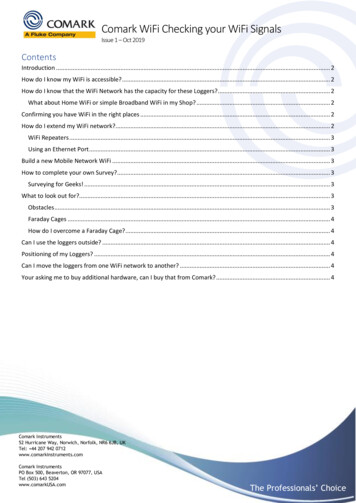
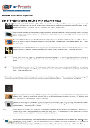
Arduino:-The Arduino Uno is a microcontroller board based on the ATmega328 (datasheet).It has 14 digital input/output pins (of which 6 can be used as PWM outputs), 6analog inputs, a 16 MHz ceramic resonator, a USB connection, a power jack, anICSP header, and a reset button. It contains everything needed to support themicrocontroller; simply connect it to a computer with a USB cable or power itwith a AC-to-DC adapter or battery to get started.The Uno differs from allpreceding boards in that it does not use the FTDI USB-to-serial driver chip.Instead, it features the Atmega16U2 (Atmega8U2 up to version R2) programmed asa USB-to-serial converter.20
The Uno is a microcontroller board based on the ATmega328P. It has 14 digitalinput/output pins (of which 6 can be used as PWM outputs), 6 analog inputs, a16 MHz quartz crystal, a USB connection, a power jack, an ICSP header and areset button. It contains everything needed to support the microcontroller;simply connect it to a computer with a USB cable or power it with a AC-to-DCadapter or battery to get started."Uno" means one in Italian and was chosen to mark the release of ArduinoSoftware (IDE) 1.0. The Uno board and version 1.0 of Arduino Software (IDE)were the reference versions of Arduino, now evolved to newer releases. The Unoboard is the first in a series of USB Arduino boards.Technical specifications:MicrocontrollerATmega328POperating Voltage 5VInput Voltage (recommended)Input Voltage (limit)Digital I/O Pins7-12V6-20V14 (of which 6 provide PWM output)PWM Digital I/O Pins6Analog Input Pins 6DC Current per I/O Pin20 mADC Current for 3.3V Pin 50 mA21
Flash Memory32 KB (ATmega328P)of which 0.5 KB used by bootloaderSRAMEEPROM2 KB (ATmega328P)1 KB (ATmega328P)Clock Speed 16 MHzLength68.6 mmWidthWeight53.4 mm25 g.Arduino Code:-#include "SoftwareSerial.h"#define DEBUG trueSoftwareSerial esp8266(2,3); // make RX Arduino line is pin 2, make TX Arduinoline is pin 3.// This means that you need to connect the TXline from the esp to the Arduino's pin 222
// and the RX line from the esp to the Arduino's pin3void setup(){Serial.begin(9600);esp8266.begin(9600); // your esp's baud rate might be ite(7,LOW);23
AT RST\r\n",2000,DEBUG); // reset modulesendData("AT CWMODE 2\r\n",1000,DEBUG); // configure as access pointsendData("AT CIFSR\r\n",1000,DEBUG); // get ip addresssendData("AT CIPMUX 1\r\n",1000,DEBUG); // configure for multipleconnectionssendData("AT CIPSERVER 1,80\r\n",1000,DEBUG); // turn on server on port 80}void loop(){if(esp8266.available()) // check if the esp is sending a message{if(esp8266.find(" IPD,")){delay(1000); // wait for the serial buffer to fill up (read all theserial data)// get the connection id so that we can then disconnect24
int connectionId esp8266.read()-48; // subtract 48 because the read()function returns// the ASCII decimal value and 0(the first decimal number) starts at 48esp8266.find("pin "); // advance cursor to "pin "int pinNumber (esp8266.read()-48)*10; // get first number i.e. if thepin 13 then the 1st number is 1, then multiply to get 10pinNumber (esp8266.read()-48); // get second number, i.e. if the pinnumber is 13 then the 2nd number is 3, then add to the first numberswitch (pinNumber){case 1://switch 1 ondigitalWrite(4,HIGH);break;case 2://switch 2 ondigitalWrite(5,HIGH);25
break;case 3://switch 3 ondigitalWrite(6,HIGH);break;case 4://switch 4 ondigitalWrite(7,HIGH);break;case 5://led ondigitalWrite(13,HIGH);break;case 6://switch 1 offdigitalWrite(4,LOW);break;case 7://switch 2 off26
digitalWrite(5,LOW);break;case 8://switch 3 offdigitalWrite(6,LOW);break;case 9://switch 4 offdigitalWrite(7,LOW);break;case 10://led italWrite(pinNumber, !digitalRead(pinNumber)); // toggle pin27
// make close commandString closeCommand "AT CIPCLOSE ";closeCommand connectionId; // append connection idcloseCommand "\r\n";sendData(closeCommand,1000,DEBUG); // close connection}}}/** Name: sendData* Description: Function used to send data to ESP8266.* Params: command - the data/command to send; timeout - the time to wait for aresponse; debug - print to Serial window?(true yes, false no)* Returns: The response from the esp8266 (if there is a reponse)*/String sendData(String command, const int timeout, boolean debug){28
String response "";esp8266.print(command); // send the read character to the esp8266long int time millis();while( (time timeout) ial.print(response);return response;}29
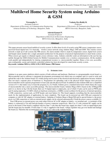
Esp 8266:-30
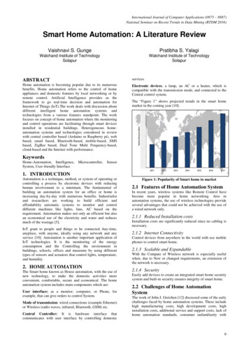
Description: The ESP8266 WiFi Module is a self contained SOC withintegrated TCP/IP protocol stack that can give any microcontroller access toyour WiFi network. The ESP8266 is capable of either hosting an application oroffloading all Wi-Fi networking functions from another application processor.Each ESP8266 module comes pre-progr
HOME AUTOMATION USING ARDUINO WIFI MODULE ESP8266 A PROJECT REPORT Submitted by ILYAS BAIG CHIKTAY MUZAMIL SALAHUDDIN DALVI in partial fulfill ment for the award of the degree of B.E IN ELECTRONICS & TELECOMMUNICATION At ANJUMAN -I-ISLAM S KALSEKAR TECHNICAL CAMPUS PAN VEL 2015 -2016. 1 Project Report Approval for B.E This project report entitled HOME AUTOMATION USING ARDUINO