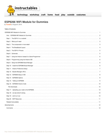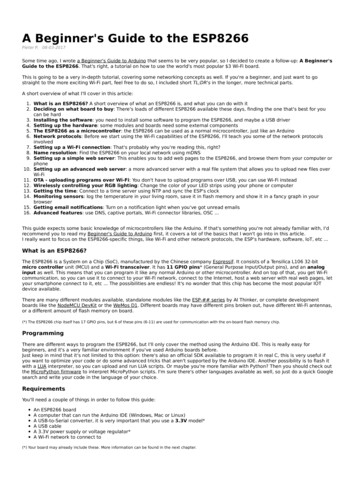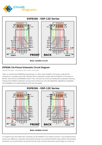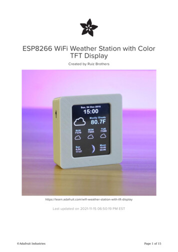
Transcription
ESP8266 Non-OSNOFO T RR ECNE OMW(NMRN DE END) SIG DENS DAT Command ExamplesVersion 1.4Espressif SystemsCopyright 2021
About This GuideThe document gives some examples of the ESP8266 AT commands that are based onESP8266 NONOS SDK. However, this SDK is no longer updated, so it is recommendedto use ESP8266 IDF AT Bin for new product designs. Refer to ESP-AT User Guidefor documentation.The document is structured as follows:ChapterTitleContentChapter 1OverviewProvides instructions on downloading AT firmware.Chapter 2Single Connection as TCP ClientIntroduces how to create a TCP client and establisha TCP connection.Chapter 3UDP TransmissionIntroduces how to create a UDP transmission.Chapter 4UART-WiFi Passthrough ModeIntroduces how to create a UART-WiFi passthroughtransmission.Chapter 5Multiple Connections as TCP ServerIntroduces how to create a TCP server.Chapter 6Q&AProvides information on where and how to consultquestions about ESP8266 AT commands.Release NotesDateVersionRelease notes2017.08V1.3Updated version.Added NRND in title page and footer.2021.08V1.4Added documentation feedback link.Updated About This Guide.Documentation Change NotificationEspressif provides email notifications to keep customers updated on changes totechnical documentation. Please subscribe here.CertificationsPlease download the product certification(s) here.
Table of Contents1. Overview .12. Single Connection as TCP Client .23. UDP Transmission .43.1. UDP (remote IP and port are fixed) .43.2. UDP (remote IP and port can be changed) .64. UART-WiFi Passthrough Mode.84.1. TCP client single connection UART-WiFi passthrough .84.2. UDP transmission UART-WiFi passthrough .95. Multiple Connections as TCP Server .116. Q&A .13
1. Overview1.OverviewHerein we introduces some specific examples on the usage of ESP8266 AT Commands.For more information about the complete instruction set, please refer to documentation4A-ESP8266 AT Instruction Set. Download ESP8266 AT Bin: http://www.espressif.com/en/support/download/at- Users can download the AT bin files refer to the README.md. PC UART terminal emulator tool, to send AT commands to the ESP8266.- The default baud rate is 115200.- PC tool should be set into the "New Line Mode", AT commands end with a new line(CR LF). Notice: EspressifAT commands have to be capitalized.Not Recommended For New Designs (NRND)1/142021.08Submit Documentation Feedback
2. Single Connection as TCP Client2.Single Connection as TCPClient1. Set WiFi mode.AT CWMODE 3// softAP station modeResponse:OK2. Connect to a router.AT CWJAP "SSID","password"// SSID and password of routerResponse:OK3. Query the ESP8266 device's IP address.AT CIFSRResponse: CIFSR:APIP,"192.168.4.1" CIFSR:APMAC,"1a:fe:34:a5:8d:c6" CIFSR:STAIP,"192.168.3.133" CIFSR:STAMAC,"18:fe:34:a5:8d:c6"OK4. Connect PC to the same router that ESP8266 is connected to. Using a network tool onthe computer to create a server.- For example, the TCP server on PC is 192.168.3.116, port 8080.5. ESP8266 connects to the server as a TCP client.AT CIPSTART "TCP","192.168.3.116",8080//protocol, server IP and portResponse:OK6. ESP8266 sends data to the server.AT CIPSEND 4// set date length which will be sent, test// enter the data,such as 4 bytesno CRResponse:Recv 4 bytesSEND OKEspressifNot Recommended For New Designs (NRND)2/142021.08Submit Documentation Feedback
2. Single Connection as TCP Client Notice: If the number of bytes inputted are more than the size defined (n):-the system will reply busy, and send the first n bytes.-and after sending the first n bytes, the system will reply SEND OK.7. When ESP8266 received data from server, it will prompt message below: IPD,n:xxxxxxxxxx// received n bytes,data xxxxxxxxxxx8. End the TCP connection.AT CIPCLOSEResponse:CLOSEDOKEspressifNot Recommended For New Designs (NRND)3/142021.08Submit Documentation Feedback
3. UDP Transmission3.UDP TransmissionUDP transmission is established via command AT CIPSTART.1. Set WiFi mode.AT CWMODE 3// softAP station modeResponse:OK2. Connect to a router.AT CWJAP "SSID","password"// SSID and password of routerResponse:OK3. Query the ESP8266 device's IP address.AT CIFSRResponse: CIFSR:APIP,"192.168.4.1" CIFSR:APMAC,"1a:fe:34:a5:8d:c6" CIFSR:STAIP,"192.168.101.133" CIFSR:STAMAC,"18:fe:34:a5:8d:c6"OK4. Connect PC to the same router as ESP8266 is connected to. Using a network tool onthe PC to create a UDP port.- For example, the PC's IP address is 192.168.101.116 and the port is 8080.5. Below is two examples on UDP transmission.3.1. UDP (remote IP and port are fixed)In UDP transmission, whether remote IP and port is fixed or not is decided by the lastparameter of "AT CIPSTART". "0" means that the remote IP and port is fixed and cannotbe changed. A specific ID is given to such connection, making sure that the data senderand receiver will not be replaced by other devices.1. Enable multiple connection.AT CIPMUX 1Response:OKEspressifNot Recommended For New Designs (NRND)4/142021.08Submit Documentation Feedback
3. UDP Transmission2. Create a UDP transmission, for example, ID is 4AT CIPSTART NNNECTOK Note:"192.168.101.110", 8080 here is the remote IP and port of UDP transmission of the opposite side, i.e., theconfiguration set by PC.1112 is the local port of ESP8266. User can self-define this port. The value of this port will be random if it’s notdefined beforehand.0 means that remote IP and port is fixed and cannot be changed. For example, if another PC also creates aUDP entity and sends data to ESP8266 port 1112. ESP8266 can receive data sent from UDP port 1112, butwhen data is sent using AT command “AT CIPSEND 4, X”, it will still be sent to the first PC end. If thisparameter is not 0, it will send to a new PC.3. Send data.AT CIPSEND 4,7// Send 7 bytes to transmission NO.4 UDPtest// enter the data,no CRResponse:Recv 7 bytesSEND OK Notice: If the number of bytes inputted are more than the size defined (n):-the system will reply busy, and send the first n bytes.-and after sending the first n bytes, the system will reply SEND OK.4. When ESP8266 received data, it will prompt message below: IPD,4,n:xxxxxxxxxx// received n bytes,data xxxxxxxxxxx5. End the UDP transmission.AT CIPCLOSE 4Response:4,CLOSEDOKEspressifNot Recommended For New Designs (NRND)5/142021.08Submit Documentation Feedback
3. UDP Transmission3.2. UDP (remote IP and port can be changed)When creating a UDP transmission, set the last parameter of "AT CIPSTART" to be "2". Itmeans that the remote IP and port can be changed.1. Create a UDP transmission.AT CIPSTART CTOK Note:"192.168.101.110", 8080 here is the remote IP and port of UDP transmission of the opposite side, i.e., theconfiguration set by PC.1112 is the local port of ESP8266. User can self-define this port. The value of this port will be random if it’s notdefined beforehand.2 means the remote IP and port will change to be the latest one that has been communicating with ESP8266.For example, if another PC also creates a UDP entity and sends data to ESP8266 port 1112. ESP8266 canreceive data sent from UDP port 1112, and when data is sent using AT command “AT CIPSEND 4, X”, it willstill be sent to the new one.2. Send data.AT CIPSEND 7// Send 7 bytes UDPtest// enter the data,no CRResponse:Recv 7 bytesSEND OK Notice: If the number of bytes inputted are more than the size defined (n):-the system will reply busy, and send the first n bytes.-and after sending the first n bytes, the system will reply SEND OK.3. To send data to other UDP terminals, you can set the target IP and port when sendingdata. For example, send 7 bytes to the 192.168.101.111, port 1000.AT CIPSEND 7,"192.168.101.111",1000// Send 7 bytes UDPtest// enter the data,no CRResponse:Recv 7 bytesSEND OK4. When ESP8266 received data, it will prompt message below:EspressifNot Recommended For New Designs (NRND)6/142021.08Submit Documentation Feedback
3. UDP Transmission IPD,n:xxxxxxxxxx// received n bytes,data xxxxxxxxxxx5. End the UDP transmission.AT CIPCLOSEResponse:CLOSEDOKEspressifNot Recommended For New Designs (NRND)7/142021.08Submit Documentation Feedback
4. UART-WiFi Passthrough Mode4. UART-WiFi Passthrough ModeUART-WiFi passthrough mode can only be enabled when ESP8266 is working as TCPclient creating a single connection, or in UDP transmission.4.1. TCP client single connection UART-WiFi passthroughHere is an example that ESP8266 station as TCP client to create a single connection andexecute UART-WiFi passthrough transmission. For ESP8266 softAP, it can be set intoUART-WiFi passthrough mode in the similar way.1. Set WiFi mode.AT CWMODE 3// softAP station modeResponse:OK2. Connect to a router.AT CWJAP "SSID","password"// SSID and password of routerResponse:OK3. Query the ESP8266 device's IP address.AT CIFSRResponse: CIFSR:APIP,"192.168.4.1" CIFSR:APMAC,"1a:fe:34:a5:8d:c6" CIFSR:STAIP,"192.168.101.133" CIFSR:STAMAC,"18:fe:34:a5:8d:c6"OK4. Connect PC to the same router as ESP8266 is connected to. Using a network tool onthe PC to create a TCP server.- For example, the PC's IP address is 192.168.101.110 and the port is 8080.5. ESP8266 connects to the server as a TCP client.AT CIPSTART "TCP","192.168.101.110",8080//protocol, server IP and portResponse:OK6. Enable UART-WiFi passthrough mode.AT CIPMODE 1EspressifNot Recommended For New Designs (NRND)8/142021.08Submit Documentation Feedback
4. UART-WiFi Passthrough ModeResponse:OK7. ESP8266 starts sending data to the server.AT CIPSENDResponse: //From now on, data received from UART will be transmitted to the server automatically.8. Stop sending dataWhen receiving a packet that contains only “ ”, the UART-WiFi passthroughtransmission process will be stopped. Then please wait at least 1 second before sendingnext AT command.Please be noted that if you input “ ” directly by typing, the “ ”, may not berecognised as three consecutive “ ” because of the Prolonged time when typing. Note:The aim of inputting “ ” is to exit UART-WiFi passthrough transmission and turn back to accept normal ATcommand, while the TCP connection still remains connected. So, we can also use command “AT CIPSEND”to turn back into UART-WiFi passthrough transmission.9. Disable UART-WiFi passthrough mode.AT CIPMODE 0Response:OK10.End the TCP connection.AT CIPCLOSEResponse:CLOSEDOK4.2. UDP transmission UART-WiFi passthroughHere is an example that ESP8266 softAP create a UDP UART-WiFi passthroughtransmission. For ESP8266 station, it can execute UDP UART-WiFi passthroughtransmission in the similar way.1. Set WiFi mode.AT CWMODE 3// softAP station modeResponse:OK2. Connect PC to ESP8266 softAP. Then using a network tool on PC to create a UDP port.EspressifNot Recommended For New Designs (NRND)9/142021.08Submit Documentation Feedback
4. UART-WiFi Passthrough Mode- For example, the PC's IP address is 192.168.4.2 and the port is 1001.3. ESP8266 create a UDP transmission of which remote IP and port are fixed.AT CIPSTART "UDP","192.168.4.2",1001,2233,0Response:OK4. Enable UART-WiFi passthrough mode.AT CIPMODE 1Response:OK5. ESP8266 starts sending data.AT CIPSENDResponse: //From now on, data received from UART will be transmitted automatically.6. Stop sending dataWhen receiving a packet that contains only “ ”, the UART-WiFi passthroughtransmission process will be stopped. Then please wait at least 1 second before sendingnext AT command.Please be noted that if you input “ ” directly by typing, the “ ”, may not berecognized as three consecutive “ ” because of the Prolonged time when typing. Note:The aim of inputting “ ” is to exit UART-WiFi passthrough transmission and turn back to accept normal ATcommand, while the TCP connection still remains connected. So, we can also use command “AT CIPSEND”to turn back into UART-WiFi passthrough transmission.7. Disable UART-WiFi passthrough mode.AT CIPMODE 0Response:OK8. Delete the UDP transmission.AT CIPCLOSEResponse:CLOSEDOKEspressifNot Recommended For New Designs (NRND)10/142021.08Submit Documentation Feedback
5. Multiple Connection as TCP Server5.Multiple Connections as TCPServerWhen ESP8266 is working as a TCP server, the multiple connections should be allowed,since there may be more than one client connecting to the ESP8266.Here is an example showing how TCP server is realized when ESP8266 is working insoftAP mode.1. Set WiFi mode.AT CWMODE 3// softAP station modeResponse:OK2. Enable multiple connections.AT CIPMUX 1Response:OK3. Create a TCP server.AT CIPSERVER 1// default port 333Response:OK4. Connect PC to ESP8266 softAP. Then using a network tool on PC to create a TCP clientand connect to the TCP server that ESP8266 created. Note:There is a timeout mechanism when ESP8266 working as a TCP server. If a TCP client has connected to theESP8266 TCP server, but there is no data transmission for a period of time, then the server will stop theconnection when timeout. To avoid such problems, please set up a data transmission circulation every 5seconds.5. Send data.AT CIPSEND 0,4 test// set date length which will be sent,// enter the data,such as 4 bytesno CRResponse:Recv 4 bytesSEND OKEspressifNot Recommended For New Designs (NRND)11/142021.08Submit Documentation Feedback
5. Multiple Connection as TCP Server Notice: If the number of bytes inputted are more than the size defined (n):-the system will reply busy, and send the first n bytes.-and after sending the first n bytes, the system will reply SEND OK.6. When ESP8266 received data from server, it will prompt message below: IPD,0,n:xxxxxxxxxx// received n bytes,data xxxxxxxxxxx7. End the TCP connection.AT CIPCLOSE 0Response:0,CLOSEDOKEspressifNot Recommended For New Designs (NRND)12/142021.08Submit Documentation Feedback
6. Q&A6.Q&AIf you have any questions about the execution of AT commands, please contact us viaEspressif Technical Inquiries. Please describe the issues that you might encounter, includingany relevant details, as follows: AT Version information or AT Command: You can use command AT GMR to acquireinformation on your current AT command version. Hardware Module information: for example, ESP-WROOM-02. Details of the test steps, for example:AT CWMODE CUR 1OKAT GMRAT version:0.23.0.0(Apr 24 2015 21:11:01)SDK version:1.0.1compile time:Apr 24 2015 21:19:31OKAT CIPSTAMAC DEF "14:CF:11:22:33:05"OK If possible, please provide the printed log information, such as:ets Jan 8 2013,rst cause: 1, boot mode: (3,3)load 0x40100000, len 26336, room 16tail 0chksum 0xdeload 0x3ffe8000, len 5672, room 8tail 0chksum 0x69load 0x3ffe9630, len 8348, room 8tail 4chksum 0xcbcsum 0xcbSDK version: 0.9.1addr not ack when tx write cmdmode : sta(18: fe: 34: 97: d5: 7b) softAP(1a: fe: 34: 97: d5: 7b)EspressifNot Recommended For New Designs (NRND)13/142021.08Submit Documentation Feedback
Disclaimer and Copyright NoticeInformation in this document, including URL references, is subject to change without notice.ALL THIRD PARTY’S INFORMATION IN THIS DOCUMENT IS PROVIDED AS IS WITH NOWARRANTIES TO ITS AUTHENTICITY AND ACCURACY.NO WARRANTY IS PROVIDED TO THIS DOCUMENT FOR ITS MERCHANTABILITY, NONINFRINGEMENT, FITNESS FOR ANY PARTICULAR PURPOSE, NOR DOES ANY WARRANTYOTHERWISE ARISING OUT OF ANY PROPOSAL, SPECIFICATION OR SAMPLE.All liability, including liability for infringement of any proprietary rights, relating to use of informationin this document is disclaimed. No licenses express or implied, by estoppel or otherwise, to anyintellectual property rights are granted herein.The Wi-Fi Alliance Member logo is a trademark of the Wi-Fi Alliance. The Bluetooth logo is aregistered trademark of Bluetooth SIG.www.espressif.comAll trade names, trademarks and registered trademarks mentioned in this document are propertyof their respective owners, and are hereby acknowledged.Copyright 2021 Espressif Systems (Shanghai) Co., Ltd. All rights reserved.EspressifNot Recommended For New Designs (NRND)14/142021.08Submit Documentation Feedback
The document gives some examples of the ESP8266 AT commands that are based on ESP8266_NONOS_SDK. However, this SDK is no longer updated, so it is recommended to use ESP8266 IDF AT Bin for new product designs. Refer to ESP-AT User Guide for documentation. The document is structured as follows: Release Notes Documentation Change Notification
