Transcription
OPALIATMIMPORTANT INFORMATION FOR THE INSTALLER AND THE OWNER TO BE KEPT BY THE OWNERINSTALLATION INSTRUCTIONS
OPALIA COLLECTIONTMINSTALLATION INSTRUCTIONSOPALIA - inst allat io nTABLE OF CONTENTIMPORTANT SAFETY INSTRUCTIONS.1PARTS & TOOLS.3SITE PREPARATION .6INSTALLATION REMOTE M OUNTING OF TURBINE WITH ACCESS UNDER BATH.7 ELECTRICAL DIAGRAMS.16 REMOTE M OUNTING OF TURBINE WITHOUT ACCESS UNDER BATH.17CUTTING TEMPLATES: ELECTRONIC CONTROLS.241 800 463.2187Monday to Thursday from 8 a.m. to 8 p.m. (EST) . Friday from 8 a.m. to 5 p.m. (EST)Printed in Canada. Copyright March 2017 BainUltra Inc. All rights reserved. 45200655
OPALIA COLLECTIONTMINSTALLATION INSTRUCTIONSIMPORTANT SAFETY INSTRUCTIONSREAD AND FOLLOW ALL INSTRUCTIONS OPALIA - inst allat io nPERTAINING TO RISKS OF FIRE, ELECTROCUTION OR PERSONAL INJURYSAVE THESE INSTRUCTIONSTHIS DOCUMENT SUPERCEDES THE INSTALLATION INSTRUCTION IN THE OWNER’S MANUAL.WARNING Risk of hyperthermia; people using medication and/or having an adverse medical history should consult a physicianbefore using a Hydro-thermo massage bathtub equipped with a heater. Risk of hyperthermia and possible drowning: do not use a Hydro-thermo massage bathtub equipped with heaterimmediately following strenuous exercise. Risk of fetal injury; pregnant or possibly pregnant women should consult a physician before using a Hydro-thermomassage bathtub equipped with a heater. Risk of accidental injury or drowning; do not use drugs or alcohol before or during the use of a Hydro-thermo massage bathtub equipped with a heater. Use this unit only for its intended purposes or as described in this manual. Use only accessories or devices recommendedby the manufacturer. Risk of hyperthermia and possible drowning. Check and adjust water temperature before use. Water temperatureexceeding 100ºF (38ºC) may be injurious to your health. To reduce the risk of injury, as with any other conventional bath, do not allow children or physically impaired peopleto use this unit unless they are closely supervised at all times. To avoid injury, exercise care when entering or exiting the Thermomasseur . The Geysair should always be connected to the hot water intake. If it is not the case, then, the Geysair should be deactivated via the bath control.RISK OF ELECTRICAL SHOCK Disconnect electric power before servicing. Do not permit electrical appliances (hair dryer, lamp, telephone, radio, television, etc.) within 5’ (1,5 m) of the Thermomasseur . Before using the Thermomasseur , its installation should be completelay finished so that a bather cannot accidentally comein contact with electrical components (turbine and power module). For indoor use only.www.bainultra.comSome products, specifications, and services mentioned in this manual are described in pending patent applications or are protected by patents.1
OPALIA COLLECTIONTMINSTALLATION INSTRUCTIONSOPALIA - inst allat io nIMPORTANT SAFETY INSTRUCTIONS (cont’d)PERTAINING TO RISKS OF FIRE, ELECTROCUTION OR PERSONAL INJURYREAD AND FOLLOW ALL INSTRUCTIONS SAVE THESE INSTRUCTIONSTHIS DOCUMENT SUPERCEDES THE INSTALLATION INSTRUCTION IN THE OWNER’S MANUAL.ELECTRICAL CONNECTIONS: Never drop or insert objects into any openings. The Thermomasseur must be connected only to a supply circuit that is protected by a 20 amp class A ground fault circuitinterrupter (GFCI). Optional therapies such as Chromotherapy and/or 2nd heated backrest and/or WarmTouchShell mustbe connected to a supply circuit that is protected by a 15 amp class A ground fault circuit interrupter (GFCI). This interrupteris supplied by a certified electrician and must be tested on a regular basis in accordance with manufacturer’s instructions.The GFCI ground must be connected. If defective, do not use the Thermomasseur . Disconnect immediately and call acertified electrician. Use 12 AWG (or greater) copper conductors that resist temperatures of at least 194ºF (90ºC). C anada only: for permanently connected units. A green-colored terminal (or a wire connector marked g., gr., groundor grounding) is provided within the terminal compartment (not applicable if unit supplied with an electric plug).To reduce the risk of electrocution, connect this terminal or connector to the grounding terminal of your electric serviceor supply panel with conductor equivalent in size to the circuit conductors supplying the equipment and be 12 AWGor more. All electrical connections must be carried out by a certified electrician and must respect federal, provincial/state,and local building codes and regulations. Install in accordance with manufacturer’s installation instructions. For Geysair-equipped baths using remote turbine installation (not mounted on the bath), grounding continuity must betested between the bath grounding terminaland the bath power supply. Failure to perform the grounding continuitytest could result in serious personal injury.WATER LEAK TEST Once plumbing is fully installed and before beginning any other work, fill the ThermoMasseur with water to overflow leveland wait 30 minutes. Check all plumbing hook-ups and bath for leaks. BainUltra is not responsible for any water damagecaused by improper installation (see Warranty section).21 800 463.2187Monday to Thursday from 8 a.m. to 8 p.m. (EST) . Friday from 8 a.m. to 5 p.m. (EST)Printed in Canada. Copyright March 2017 BainUltra Inc. All rights reserved. 45200655
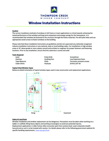
OPALIA COLLECTIONTMINSTALLATION INSTRUCTIONSSTANDARD PARTS - PLUMBINGDESCRIPTIONOPALIA - inst allat io nPARTS & TOOLS REQUIREDAQTYAPlated drain clicker1BStrainer1CRubber seal1DTee PVC Drain shoe1EAnchor set*1BCDEOPTIONAL PARTS - PLUMBINGDESCRIPTIONQTYFBrass drain shoe1G4 in. brass tailpiece1HNylon conic shaped seal for drain1IBrass nut2JBrass pipe 1-1/2” x 3” with flange1KNylon flat seal with flange1L1-1/2” male threaded adaptor1FLKJIHOPTIONAL PART – PLUMBING*ENSEMBLE ISLAND TUB DRAIN (ITD) Makes installation and servicing easierfor removal of bath. Allows you to connect the bath draintailpiece to the plumbing pipe withoutneed for tightening to seal once the bathis lowered to the floor.G SET INCLUDES A CONIC SHAPED SEAL ANDA 6 IN. (15 CM) BRASS TAILPIECE.* : REQUIRED WHEN NO ACCESS IS POSSIBLEUNDER the BATH.www.bainultra.comSome products, specifications, and services mentioned in this manual are described in pending patent applications or are protected by patents.3
OPALIA COLLECTIONTMINSTALLATION INSTRUCTIONSOPALIA - inst allat io nPARTS & TOOLS REQUIREDSTANDARDS PARTS – FLOOR ANCHORDESCRIPTIONNQTYMThreaded anchor2N1/2” Nut – 13 zinc2O1/2” Flat washer2P#10 X 1-1/2” Countersunk head screw12QCover sealsPOQM2STANDARDS PARTS – THERMOMASSEUR DESCRIPTIONQTYATurbineBMiaPlus Control1CMiaMulti Control (option)1D15’ extension cord11 BACD41 800 463.2187Monday to Thursday from 8 a.m. to 8 p.m. (EST) . Friday from 8 a.m. to 5 p.m. (EST)Printed in Canada. Copyright March 2017 BainUltra Inc. All rights reserved. 45200655
OPALIA COLLECTIONTMINSTALLATION INSTRUCTIONSOPALIA - inst allat io nPARTS & TOOLS REQUIREDPARTS & TOOLS REQUIREDInstallation template48-inch levelMeasuring tapeTeflon tapeCaulking gunSiliconeABS & PVC GlueSquare/Phillips #2 Screwdriver3/4” RatchetAdjustable clampswww.bainultra.comSome products, specifications, and services mentioned in this manual are described in pending patent applications or are protected by patents.5
OPALIA COLLECTIONTMINSTALLATION INSTRUCTIONSOPALIA - inst allat io nSITE PREPARATIONPLUMBING See faucet manufacturer’s specifications for zoningand plan water supply location accordingly. Position drain according to bath’s technical specifications.WARNING Baths from OpaliaTM collection cannot be drilledfor faucet installation. Faucets must be freestandingor wall-mounted models.1500 LB(680 KG)FLOORBEDDING Before installing, ensure that the floor underneath the bath can support 1500 lb (680 kg). The bath may sit directlyon the floor. No special bedding installation is recommended by manufacturer, the bathtub can sit directly on the floor. However, the bath can also sit on a concrete bedding. In that case, it is recommended to isolate the concrete between two plasticsheets: one installed on the floor and the other under the bath.SERVICE ACCESS AND VENTILATION A service access is necessary. Minimum dimensions are 22 in. x 18 in. (55 cm x 46 cm)to properly reach all electrical components of the system. An air vent is necessary. Minimum dimensions are: 2 in. x 4 in. (5 cm x 10 cm)to ensure proper functioning of the turbine.There is a technical specification sheet for each BainUltra ThermoMasseur which includes information such as necessarydimensions of site before installation.If you do not already have the technical specifications, download it from the BainUltra Web site at: bainultra.comor call us at: 1 800 463-2187.61 800 463.2187Monday to Thursday from 8 a.m. to 8 p.m. (EST) . Friday from 8 a.m. to 5 p.m. (EST)Printed in Canada. Copyright March 2017 BainUltra Inc. All rights reserved. 45200655
OPALIA COLLECTIONTMINSTALLATION INSTRUCTIONSOPALIA - inst allat io nREMOTEPARTS & TOOLSMOUNTINGREQUIREDOF TURBINE WITH ACCESS UNDER BATHPLUMBING – FLOOR LAYOUT FOR PIPES AND ACCESS OPALIA 6938NOTE : Please refer to the Installation Template provided with your OPALIA bath. However, if it is missing, please contact usat 1-800-463-2187 to order it.1PLUMBINGHELPFUL TIP: Carefully place the tubon its side, on a blanketor a corrugated cardboard.Measure &Align (2x)Anchor Mwww.bainultra.comSome products, specifications, and services mentioned in this manual are described in pending patent applications or are protected by patents.7
OPALIA COLLECTIONTMINSTALLATION INSTRUCTIONSOPALIA - inst allat io nREMOTE MOUNTING OF TURBINE WITH ACCESS UNDER BATHASTANDARD PARTS - PLUMBINGDESCRIPTIONBQTYAPlated drain clicker1BStrainer1CRubber seal1DTee PVC Drain shoe1ABCDCDOPTIONAL PARTS - PLUMBINGDESCRIPTIONQTYFTee Brass drain shoe1G4 in. brass tailpiece1HNylon conic shaped seal for drain1IBrass nut1JBrass pipe 1-1/2” x 3” with flange1KNylon flat seal with flange1L1-1/2” male threaded adaptor1FlexibleOverflow Piping(Factory installed)FGL81 800 463.2187KJIHMonday to Thursday from 8 a.m. to 8 p.m. (EST) . Friday from 8 a.m. to 5 p.m. (EST)Printed in Canada. Copyright March 2017 BainUltra Inc. All rights reserved. 45200655
OPALIA COLLECTIONTMINSTALLATION INSTRUCTIONS2OPALIA - inst allat io nREMOTE MOUNTING OF TURBINE WITH ACCESS UNDER BATHTURBINE & GEYSAIR INSTALLATION (FOR THERMOMASSEUR )Geysair Hose andBack Flow Preventer1-1/2 I.D. PVC AIR INTAKE PIPE(«TIGERFLEX » FLEXIBLE PVC)1-1/2 I.D. ABS, PVC PIPE(RIGID or «TIGERFLEX»)& Fittings (not included)Hot Water SupplyTURBINE REMOTEMOUNTINGSEE STEP 7 page 13WARNING Access to Geysair backflow preventer is necessary for cleaning of the filter. Baths from Opalia collection cannot be drilled for faucet installation. Faucets must be freestandingor wall-mounted models. Geysair component cannot be remote mounted. It must stay at original position, attached to bath.Must never be unplugged.3ELECTRICAL WIRING OF OPTIONAL COMPONENTSREMOTE MOUNTINGof CONTROL MODULESSEE STEP 8 page 14www.bainultra.comSome products, specifications, and services mentioned in this manual are described in pending patent applications or are protected by patents.9
OPALIA COLLECTIONTMINSTALLATION INSTRUCTIONSOPALIA - inst allat io nREMOTE MOUNTING OF TURBINE WITH ACCESS UNDER BATH4BATH INSTALLATION - OPALIA 6938HELPFUL TIPS: Carefully place the tub on its side,on a blanket or a corrugated cardboard. To easily manipulate the bathtubin a safe way during installation,we recommend using moving straps.FlooranchorMMeasure& Align (2x)WARNING Be sure the floor is leveled. Use shims as needed. Do not remove the protective plastic film on the tuband place a drop-cloth in the tub during installationto protect the acrylic. A pply a bead of silicone around the perimeterof the bath once on the floor. The tub must be securely anchored to floor. Connect the drain. Fix bath to floor by using washers «O» and nuts «N».FloorSurface Install the bath on anchors « M » previouslyscrewed to floor. Remove exceeding silicone. Place cover seals «Q» over openings.1“ MinimumNOQM101 800 463.2187AnchorMonday to Thursday from 8 a.m. to 8 p.m. (EST) . Friday from 8 a.m. to 5 p.m. (EST)Printed in Canada. Copyright March 2017 BainUltra Inc. All rights reserved. 45200655
OPALIA COLLECTIONTMINSTALLATION INSTRUCTIONS5ELECTRONIC CONTROL INSTALLATION – MIAPLUS & MIAMULTI (OPTIONAL) LOCATIONLOCATION: Determine the most convenient location, on the wall close to tub. Peel off the protective film of stickerbehind the control. You can add a silicone bead to secure to the wall.WARNING Baths from Opalia collection cannot be drilled for faucet installation. Faucets must be freestanding or wall-mounted models.TM DRILLING OF WALL: Refer to the Cutting Template on page 24 for the location and diameter of the holes.TOOLS REQUIREDJig saw with fine cut bladeDrill1/4 in. drill bitTOUCH PAD INSTALLATIONPush wiring through drilled holes.Remove protective film from watertight seal.Secure to the wall with permanent waterproofsealant (mold-free clear silicone for bathrooms).Secure temporarily with a tape for about 24 h.5ELECTRONIC CONTROL INSTALLATION – DOTTOOLS REQUIRED7/8 in. Hole sawDrillTOUCH PAD INSTALLATIONDOT WarmTouchShell (WTS)Push wiring through drilled holes.Remove protective film from watertight seal.Secure to the wall with permanent waterproofsealant (mold-free clear silicone for bathrooms).Secure temporarily with a tape for about 24 h.DOT Chromatherapy (LED)WARNING If the control is not factory installed, you will find it attached to the turbine, or to the electronic control modules.www.bainultra.comSome products, specifications, and services mentioned in this manual are described in pending patent applications or are protected by patents.11OPALIA - inst allat io nREMOTE MOUNTING OF TURBINE WITH ACCESS UNDER BATH
OPALIA COLLECTIONTMINSTALLATION INSTRUCTIONSOPALIA - inst allat io nREMOTE MOUNTING OF TURBINE WITH ACCESS UNDER BATH6REMOTE MOUNTING OF TURBINEBottom of door hen located in anWenclosed location.1”FloorWARNING Choose a location for the turbine with the shortest possible distance from the Thermomasseur bath, no morethan 15 ft. (4,6m), and a maximum of six elbow directional changes to ensure system performance. It can be underthe floor, in a closet or any other place that can hide the turbine and if needed optional modules. Easy access mustremain possible at all time and sufficient air ventilation is necessary for turbine. A service access is necessary. Minimum dimensions are 22 in. x 18 in. (55 cm x 46 cm) to properly reach all electricalcomponents of the system. An air vent is necessary. Minimum dimensions are: 2 in. x 4 in. (5 cm x 10 cm) to ensure proper functioning of the turbine. Geysair cannot be remotely installed.121 800 463.2187Monday to Thursday from 8 a.m. to 8 p.m. (EST) . Friday from 8 a.m. to 5 p.m. (EST)Printed in Canada. Copyright March 2017 BainUltra Inc. All rights reserved. 45200655
OPALIA COLLECTIONTMINSTALLATION INSTRUCTIONS7OPALIA - inst allat io nREMOTE MOUNTING OF TURBINE WITH ACCESS UNDER BATHREMOTE MOUNTING OF TURBINE - AIR PIPE (THERMOMASSEUR )1-1/2 I.D. ABS, PVC PIPE(RIGID or «TIGERFLEX»)& Fittings (not included)7REMOTE MOUNTING OF TURBINE - ELECTRICAL CONNECTIONS (THERMOMASSEUR ) See page 16 for electrical diagramGEYSAIREXTENSION CORD(If required for longer distance,contact BainUltra for ordering)GEYSAIR CONNECTIONTO GFCI OutletUnited StatesJunction boxCanadaWARNING For Geysair equipped baths using remote turbine installation (not mounted on the bath), grounding continuitymust be tested between the bath grounding terminaland the bath power supply.Failure to perform the grounding continuity test could result in serious personal injury.www.bainultra.comSome products, specifications, and services mentioned in this manual are described in pending patent applications or are protected by patents.13
OPALIA COLLECTIONTMINSTALLATION INSTRUCTIONSOPALIA - inst allat io nPARTS & TOOLS REQUIRED8REMOTE MOUNTING OF TURBINE – ELECTRICAL CONNECTIONS OF OPTIONAL THERAPIES See page 16 for electrical diagram.Match the colors of theplug-in cables with thoseof the turbine terminalsEDA: 2nd Heated BackrestB: Chromatherapy (LED)C: MiaPlus CD: MiaMulti (Option) E : AromaCloud BAJunction boxCanadaTO GFCI OutletUnited StatesJunction boxCanadaTO GFCI OutletUnited StatesWARNING Electrical outlet must be installed by a certified electrician. Installation must be conducted in accordance with all local,provincial/state, and federal building/electrical codes and regulation. Connect electrical supply only after all low voltage wiring is properly installed on turbine. If you did not follow this last step, shut off and then restart your home’s circuit breaker. Turbine and air pipe should be clear of building materials and wiring.141 800 463.2187Monday to Thursday from 8 a.m. to 8 p.m. (EST) . Friday from 8 a.m. to 5 p.m. (EST)Printed in Canada. Copyright March 2017 BainUltra Inc. All rights reserved. 45200655
OPALIA COLLECTIONTMREMOTE MOUNTING OF TURBINE WITH ACCESS UNDER BATH8REMOTE MOUNTING OF OPTIONAL THERAPIES (TUB ONLY) – ELECTRICAL CONNECTIONS See page 16 for electrical diagram.EA : WarmTouchShell B: Chromatherapy (LED)C : DOT WarmTouchShell DCD : DOT ChromatherapyE : AromaCloud BACJunction boxCanadaDOT WarmTouchShell (WTS)DJunction boxCanadaTO GFCI OutletUnited StatesTO GFCI OutletUnited StatesDOT Chromatherapy (DEL)www.bainultra.comSome products, specifications, and services mentioned in this manual are described in pending patent applications or are protected by patents.15OPALIA - inst allat io nINSTALLATION INSTRUCTIONS
OPALIA COLLECTIONTMINSTALLATION INSTRUCTIONSOPALIA - inst allat io nPARTSREMOTE& TOOLSMOUNTINGREQUIREDOF TURBINE WITH ACCESS UNDER BATHELECTRICAL DIAGRAM – 20A THERMOMASSEUR et 15A THERAPY15A CIRCUIT15A CIRCUIT20A CIRCUITNEUTRAL NL LOADNEUTRAL N NEUTRAL NL LOADL LOADGROUNDFAULT CIRCUITINTERRUPTERSGROUNDGROUNDFAULT CIRCUITFAULT CIRCUITINTERRUPTERSINTERRUPTERSJUNCTION JUNCTIONBOXBOXJUNCTIONBOXFlexibleOverflow Piping(Factory installed)NLNTURBINE WITH GEYSAIR(FOR MIAPLUS , MIAMULTI )16LNL NLGEYSAIRMODULEAROMACLOUD TURBINE WITHOUTINMIX MIAMULTI )(AROMATHERAPY) (FOR MIAPLUS , (CHROMATHERAPY)1 800 463.2187NLAIRSTREME(WARMTOUCHSHELL )Monday to Thursday from 8 a.m. to 8 p.m. (EST) . Friday from 8 a.m. to 5 p.m. (EST)Printed in Canada. Copyright March 2017 BainUltra Inc. All rights reserved. 45200655
OPALIA COLLECTIONTMINSTALLATION INSTRUCTIONS1OPALIA - inst allat io nPARTS& TOOLSREQUIREDREMOTEMOUNTINGOF TURBINE WITHOUT ACCESS UNDER BATHPLUMBING - ISLAND TUB DRAIN INSTALLATION HELPFUL TIP: Carefully place the tubon its side, on a blanketor a corrugated cardboard.AnchorMWARNING R efer to supplied instructionsfor Island Tub Drain installation.Measure &Align (2x)IslandTub DrainOPTIONAL PARTS - PLUMBING(DESCRIPTIONQTYFTee Brass drain shoe1G6 in. brass tailpiece1HNylon conic shaped seal for drain1IBrass nut1JNylon flat seal with flange1KNylon flat seal with flange1L1-1/2” male threaded adaptor1FFlexibleOverflow Piping(Factory installed)LKJIHwww.bainultra.comSome products, specifications, and services mentioned in this manual are described in pending patent applications or are protected by patents.G17
OPALIA COLLECTIONTMINSTALLATION INSTRUCTIONSOPALIA - inst allat io nREMOTE MOUNTING OF TURBINE WITHOUT ACCESS UNDER BATH2TURBINE & GEYSAIR INSTALLATION (FOR THERMOMASSEUR ) PASSAGE FOR THE ELECTRICAL WIRING OF OPTIONAL THERAPIESWARNINGI F THE AIR PIPING CONNECTIONS AND POWER SUPPLY OF THERAPEUTIC OPTIONS HAVE TO BE AT FLOOR LEVEL, YOUMUST MAKE AN OPENING ON ONE SIDE OF THE BATH, AS CLOSE AS POSSIBLE TO TURBINE AND CONTROLS. Do not drill through the interior shell. The size of the opening must be large enough to allow wires and pipes to go through.TOOLS REQUIREDDrill1/4 in. drill bitJig saw with fine cut bladeOPALIA 6938 Air pipe* Geysair E lectric cables(Optional therapies)(*) : Location of air pipe can differ from drawing.181 800 463.2187Monday to Thursday from 8 a.m. to 8 p.m. (EST) . Friday from 8 a.m. to 5 p.m. (EST)Printed in Canada. Copyright March 2017 BainUltra Inc. All rights reserved. 45200655
OPALIA COLLECTIONTMINSTALLATION INSTRUCTIONS2OPALIA - inst allat io nREMOTE MOUNTING OF TURBINE WITHOUT ACCESS UNDER BATHTURBINE & GEYSAIR INSTALLATION (FOR THERMOMASSEUR )Geysair Hose andBack Flow Preventer1-1/2 I.D. PVC AIR INTAKE PIPE(«TIGERFLEX » FLEXIBLE PVC)1-1/2 I.D. ABS, PVC PIPE(RIGID or «TIGERFLEX»)& Fittings (not included)Hot Water SupplyTURBINE REMOTEMOUNTINGSEE STEP 7 page 13WARNING Access to Geysair backflow preventer is necessary for cleaning of the filter. Baths from Opalia collection cannot be drilled for faucet installation. Faucets must be freestandingor wall-mounted models. Geysair component cannot be remote mounted. It must stay at original position, attached to bath.Must never be unplugged.3ELECTRICAL WIRING OF OPTIONAL COMPONENTSREMOTE MOUNTINGof CONTROL MODULESSEE STEP 8 page 14www.bainultra.comSome products, specifications, and services mentioned in this manual are described in pending patent applications or are protected by patents.19
OPALIA COLLECTIONTMINSTALLATION INSTRUCTIONSOPALIA - inst allat io nREMOTEPARTS & MOUNTINGTOOLS REQUIREDOF TURBINE WITHOUT ACCESS UNDER BATH4 BATH INSTALLATION – OPALIA WITH ISLAND TUB DRAIN HELPFUL TIPS: Carefully place the tubon its side, on a blanketor a corrugated cardboard. To easily manipulate the bathtubin a safe way during installation,we recommend using moving straps.Anchor MWARNINGMeasure& Align (2x) Be sure the floor is leveled. Use shims as needed. Do not remove the protective plastic film on the tub and place a drop-cloth in the tub during installation to protect the acrylic. Apply a bead of silicone around the perimeter of the bath once on the floor. Connect the drain. Install bath on anchors « M» previously screwed to the floor. Remove exceeding silicone. Connect the drain. Fix bath to floor by using washers «O» and nuts «N». Install the bath on anchors « M » previouslyscrewed to floor. Remove exceeding silicone. Place cover seals «Q» over openings.NOQM201 800 463.2187Monday to Thursday from 8 a.m. to 8 p.m. (EST) . Friday from 8 a.m. to 5 p.m. (EST)Printed in Canada. Copyright March 2017 BainUltra Inc. All rights reserved. 45200655
OPALIA COLLECTIONTMINSTALLATION INSTRUCTIONS4OPALIA - inst allat io nREMOTE MOUNTING OF TURBINE WITHOUT ACCESS UNDER BATHBATH INSTALLATION DRAIN CONNECTION WITH ISLAND TUB DRAIN (ITD) - INFORMATIONWARNING Refer to supplied instructionsfor ISLAND TUB DRAIN installation.ISLAND TUB DRAIN Floor surfaceWARNINGUse the 6 in. (15 cm) tail piecesupplied with Island Tub Drain www.bainultra.comSome products, specifications, and services mentioned in this manual are described in pending patent applications or are protected by patents.21
OPALIA COLLECTIONTMOPALIA - inst allat io nINSTALLATION INSTRUCTIONSPARTS& TOOLSREQUIREDREMOTEMOUNTINGOF TURBINE WITHOUT ACCESS UNDER BATHFOR THE NEXT STEPS, SEE SECTION : REMOTE MOUNTING OF TURBINE WITH ACCESS UNDER THE BATH5 ELECTRONIC CONTROL INSTALLATION – MIAPLUS & MIAMULTI (OPTION).115 ELECTRONIC CONTROL INSTALLATION – DOT (THERAPIES).116 REMOTE MOUNTING OF TURBINE.127 REMOTE MOUNTING OF TURBINE – AIR PIPE (THERMOMASSEUR ).137 REMOTE MOUNTING OF TURBINE – ELECTRICAL CONNECTIONS (THERMOMASSEUR )).138 REMOTE MOUNTING OF TURBINE – ELECTRICAL CONNECTIONS OF OPTIONAL THERAPIES.148 REMOTE MOUNTING OF OPTIONAL THERAPIES – ELECTRICAL CONNECTIONS.15ELECTRICAL DIAGRAM - THERMOMASSEUR & THERAPIES.16221 800 463.2187Monday to Thursday from 8 a.m. to 8 p.m. (EST) . Friday from 8 a.m. to 5 p.m. (EST)Printed in Canada. Copyright March 2017 BainUltra Inc. All rights reserved. 45200655
OPALIAOPALIACUTTING TEMPLATES / GABARITS DE PERÇAGE 1.625"[4.1 cm]Cut-out for MiaMulti infraredTrou pour infrarouge MiaMulti 1.625"[4.1 cm]0.875"[2.2 cm]1.375"[3.5 cm]1.625" 0.04"1.625"[4.1 cm 0.1 cm][4.1 cm]1.125"0.875"[2.9 cm]R0.125"[2.2 cm][R0.3 cm]1.625" 0.04"[4.1 cm 0.1 cm]1.125"[2.9 cm]1.375"[3.5 cm] R0.125"[R0.3 cm]1.375"[3.5 cm] 1.063"[2.7 cm]1.063"[2.7 cm][5.5 cm]MIAPLUS & MIAMULTIMIAPLUS & MIAMULTI2.165"5.591" [14.2 cm]Control cut-outTrou du contrôleControl outlineContour du contrôleControl cut-outTrou du contrôleControl5.591"outline[14.2 cm]Contour du contrôle2.165"[5.5 cm]R0.250"[R0.6 cm]R0.250" Control cut-out[R0.6 cm] Trou du contrôleControl outlineContour du contrôleR0.250"[R0.6 cm]11.313"[28.7 cm]11.313"[28.7 cm]PRISE D'AIR - OUVERTUREAIR INTAKE - OPENINGAIR INTAKE - OPENINGPRISE D'AIR 11.063"- OUVERTURE[28.1 cm]PRISE D'AIR - OUVERTURE11.063"[28.1 cm]1 800 463.21872.165"[5.5 cm]1.625" 0.04"[4.1 cm 0.1 cm]AIR INTAKE - OPENING1.063"[2.7 cm]5.125" 0.04"[13.0 cm 0.1 cm]MIAPLUS & MIAMULTIR0.125"[R0.3 cm]11.313"[28.7 cm]245.125" 0.04"[13.0 cm 0.1 cm]5.591" [14.2 cm] 0.875"[2.2 cm]Cut-out for MiaMulti infraredTrou pour infrarouge MiaMulti 1.125"[2.9 cm]5.125" 0.04"[13.0 cm 0.1 cm]Monday to Thursday from 8 a.m. to 8 p.m. (EST) . Friday from 8 a.m. to 5 p.m. (EST)Du lundi au jeudi, De 8 h à 20 h (HE) . Vendredi de 8 h à 17 h (HE)Printed in Canada. Copyright March 2017 BainUltra Inc. All rights reserved. 45200655Imprimé au Canada. Copyright mars 2017 BainUltra inc. Tous droits réservés.11.063"[28.1 cm]0.813"[2.1 cm]0.813"[2.1 cm]R0.125"[R0.3 cm]R0.125"[R0.3 cm]0.813"[2.1 cm]R0.125"[R0.3 cm]www.bainultra.comSome products, specifications, and services mentioned in this manual are described in pending patent applications or are protected by patents.Certains produits, spécifications et services mentionnés dans le présent manuel sont décrits dans des demandes de brevets en instance ou protégés par des brevets.CU TTI NG TEM PL AT ES / GA B AR ITS D E PERÇAGECut-out for MiaMulti infraredTrou pour infrarouge MiaMulti CUTTING TEMPLATES / GABARITS DE PERÇAGE25
ENSEMBLE ISLAND TUB DRAIN (ITD) Makes installation and servicing easier for removal of bath. Allows you to connect the bath drain tailpiece to the plumbing pipe without need for tightening to seal once the bath is lowered to the floor. SET INCLUDES A CONIC SHAPED SEAL AND A 6 IN. (15 CM) BRASS TAILPIECE.