Transcription
Vulcan SeriesInstallation ManualENGLISHbandg.com
PrefaceDisclaimerAs Navico is continuously improving this product, we retain theright to make changes to the product at any time which may not bereflected in this version of the manual. Please contact your nearestdistributor if you require any further assistance.It is the owner’s sole responsibility to install and use the equipmentin a manner that will not cause accidents, personal injury orproperty damage. The user of this product is solely responsible forobserving safe boating practices.NAVICO HOLDING AS AND ITS SUBSIDIARIES, BRANCHES ANDAFFILIATES DISCLAIM ALL LIABILITY FOR ANY USE OF THIS PRODUCTIN A WAY THAT MAY CAUSE ACCIDENTS, DAMAGE OR THAT MAYVIOLATE THE LAW.Governing Language: This statement, any instruction manuals, userguides and other information relating to the product(Documentation) may be translated to, or has been translated from,another language (Translation). In the event of any conflict betweenany Translation of the Documentation, the English language versionof the Documentation will be the official version of theDocumentation.This manual represents the product as at the time of printing.Navico Holding AS and its subsidiaries, branches and affiliatesreserve the right to make changes to specifications without notice.CopyrightCopyright 2016 Navico Holding AS.WarrantyThe warranty card is supplied as a separate document.In case of any queries, refer to the brand website of your unit orsystem: bandg.com.Regulatory statementsThis equipment is intended for use in international waters as well ascoastal sea areas administered by the USA, and countries of the E.U.and E.E.A.Preface Vulcan Series Installation Manual3
This equipment complies with: CE under 2014/53/EU Directive The requirements of level 2 devices of the Radio communications(Electromagnetic Compatibility) standard 2008 Part 15 of the FCC Rules. Operation is subject to the followingtwo conditions: (1) this device may not cause harmfulinterference, and (2) this device must accept any interferencereceived, including interference that may cause undesiredoperation.The relevant Declaration of conformity is available in the Vulcansection on the following website: bandg.com.Industry CanadaIC RSS-GEN, Sec 7.1.3 Warning Statement- (Required forlicense exempt devices)This device complies with Industry Canada license-exempt RSSstandard(s). Operation is subject to the following two conditions: (1)this device may not cause interference, and (2) this device mustaccept any interference, including interference that may causeundesired operation of the device.Le présent appareil est conforme aux CNR d’IndustrieCanada applicables aux appareils radio exempts de licence.L’exploitation est autorisée aux deux conditions suivantes: (1)l’appareil ne doit pas produire de brouillage, et (2) l’utilisateur del’appareil doit accepter tout brouillage radioélectrique subi, même sile brouillage est susceptible d’en compromettre le fonctionnement.WarningThe user is cautioned that any changes or modifications notexpressly approved by the party responsible for compliance couldvoid the user’s authority to operate the equipment.This equipment generates, uses and can radiate radio frequencyenergy and, if not installed and used in accordance with theinstructions, may cause harmful interference to radiocommunications. However, there is no guarantee that theinterference will not occur in a particular installation. If thisequipment does cause harmful interference to radio or televisionreception, which can be determined by turning the equipment off4Preface Vulcan Series Installation Manual
and on, the user is encouraged to try to correct the interference byone or more of the following measures: Reorient or relocate the receiving antenna Increase the separation between the equipment and receiver Connect the equipment into an outlet on a circuit different fromthat of the receiver Consult the dealer or an experienced technician for helpCountries of intended use in the EUAT - AustriaBE - BelgiumBG - BulgariaCY - CyprusCZ - Czech RepublicDK - DenmarkEE - EstoniaFI - FinlandFR - FranceDE - GermanyGR - GreeceHU - HungaryIS - IcelandIE - IrelandIT - ItalyLV - LatviaLI - LiechtensteinLT - LithuaniaLU - LuxembourgMT - MaltaNL - NetherlandsNO - NorwayPL - PolandPT - PortugalRO - RomaniaSK - Slovak RepublicPreface Vulcan Series Installation Manual5
SI - SloveniaES - SpainSE - SwedenCH - SwitzerlandTR - TurkeyUK - United KingdomTrademarksLowrance and Navico are registered trademarks of Navico.Simrad is used by license from Kongsberg.Navionics is a registered trademark of Navionics, Inc.NMEA and NMEA 2000 are registered trademarks of the NationalMarine Electronics Association.SiriusXM is a registered trademark of Sirius XM Radio Inc.Fishing Hot Spots is a registered trademark of Fishing Hot Spots Inc.Copyright 2012 Fishing Hot Spots.FUSION-Link Marine Entertainment Standard is a registeredtrademark of FUSION Electronics Ltd.C-MAP is a trademark of Jeppesen.The terms HDMI and HDMI High-Definition Multimedia Interface,and the HDMI Logo are trademarks or registered trademarks ofHDMI Licensing LLC in the United States and other countries.SD and microSD are trademarks or registered trademarks ofSD-3C, LLC in the United States, other countries or both.Wi-Fi is a registered trademark of the Wi-Fi Alliance .Additional mapping data: Copyright 2012 NSI, Inc.: Copyright 2012 by Richardson’s Maptech.Bluetooth is a registered trademark of Bluetooth SIG, Inc.Navico product referencesThis manual refers to the following Navico products: Broadband Sounder (Broadband Sounder) DownScan Imaging (DownScan) DownScan Overlay (Overlay) GoFree (GoFree)6Preface Vulcan Series Installation Manual
INSIGHT GENESIS (Insight Genesis) SonicHub (SonicHub)About this manualThis manual is a reference guide for installing the Vulcan Seriesunits.Important text that requires special attention from the reader isemphasized as follows:ÚNote: Used to draw the reader’s attention to a comment orsome important information.Warning: Used when it is necessary to warnpersonnel that they should proceed carefully toprevent risk of injury and/or damage to equipment/personnel.Preface Vulcan Series Installation Manual7
8Preface Vulcan Series Installation Manual
Contents11 Check the contents1112Vulcan 5 box contentsVulcan 7 FS box contents13 Overview131416Front controlsRear connectionsCard reader17 Installation17182020Mounting locationBracket mountingPanel mountingTransducer installation21 Wiring2122232425252728GuidelinesPower ConnectionsPower Control connectionExternal alarmConnecting control devicesNMEA 2000 backboneCZone connection to NMEA 2000Transducer connection29 Software Setup2929293132334447485152First time startupTime and DateData source selectionSonar setupStructureScanAutopilot setupFuel setupCZone setupWireless setupNMEA 2000 setupSoftware updates and data backupContents Vulcan Series Installation Manual9
55 Accessories56 Supported data56NMEA 2000 compliant PGN List61 icalInterfaces63 Dimensional drawings636310Vulcan 5 Dimensional drawingsVulcan 7 FS Dimensional drawingsContents Vulcan Series Installation Manual
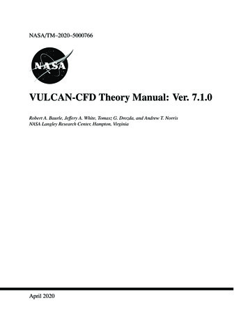
1Check the contentsCheck the contents of the box for your unit.Vulcan 5 box contents3458679210InstInstallatioInstallation ManInstallation Manualalla n M ualtion d omg.cband omg.cband omg.com111Vulcan 52Sun cover3Panel mount gasket4Cap (2x on NMEA 2000 and Sonar connectors)5Fuse holder (ATC blade)6Fuse (3 amp)7Power/NMEA 2000 cable8Panel mount screws (4x #10 x 1/2" PN HD SS)9Quick Release Bracket screws (4x #10 x 3/4" PN HD SS)10 Quick Release Bracket11 Documentation packCheck the contents Vulcan Series Installation Manual11
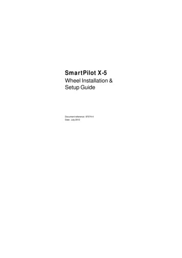
Vulcan 7 FS box contents3458697210InstInstallatioInstallation ManuInstallation Manalla n M ualaltion d omg.cband omg.cband omg.com121Vulcan 7 FS2Sun cover3Panel mount gasket4Caps (2x, on NMEA 2000 and Sonar connectors)5Fuse holder (ATC blade)6Fuse (3 amp)7Power cable8Panel mount screws (4x #10 x 1/2" PN HD SS)9U Bracket mount screws (4x #10 x 3/4" PN HD SS)10 U Bracket11 Bracket knobs (2x)12 Documentation pack12Check the contents Vulcan Series Installation Manual11
2OverviewThe unit has a built-in CHIRP/Broadband and StructureScan sonar.The Vulcan units can network over NMEA 2000, this allows access tosensor data.The unit has built-in high speed GPS receiver (10Hz) and supportsInsight charts from Navico including Insight Genesis. The systemalso supports charts from Navionics and Jeppesen as well ascontent created by a variety of third party mapping providers in theAT5 format. For a full selection of available charts, visitgofreeshop.com, c-map.jeppesen.com, or navionics.com.The unit may be mounted to the vessel with the supplied mountingbracket, or panel mounted on the dash.The unit is intended for 12 V DC operation and will accept themoderate fluctuations commonly seen in DC systems.Front controls1Touch screen2Power buttonPress and hold to turn the unit ON/OFF.Press once to display the System Controls dialog.Overview Vulcan Series Installation Manual13
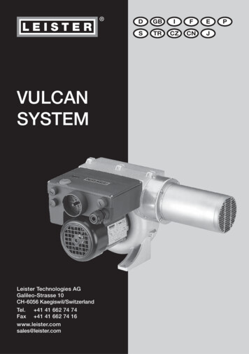
Rear connectionsVulcan 5 rear connectionsSONAR114PWR/N2K231Sonar - CHIRP, Broadband, DownScan, and SideScanimaging (dependent on the transducer)2Card reader3Power 12 V DC supply input and NMEA 2000Overview Vulcan Series Installation Manual
Vulcan 7 FS rear connections4NMEA2000POWERSONAR1231NMEA 2000 - data input / output2Power - 12 V DC supply input3Sonar - CHIRP, Broadband, DownScan, and SideScanimaging (dependent on the transducer)4Card readerOverview Vulcan Series Installation Manual15
Card readerUsed for attaching a microSD memory card. The memory card canbe used for detailed chart data, software updates, transfer of userdata, and system backup.The card reader door is opened by pulling the rubber cover open.The card reader door should always be securely shut immediatelyafter inserting or removing a card, in order to prevent possible wateringress.Card reader on the Vulcan 516Overview Vulcan Series Installation ManualCard reader on the Vulcan 7 FS
3InstallationMounting locationChoose the mounting locations carefully before you drill or cut. Theunit should be mounted so that the operator can easily use thecontrols and clearly see the screen. Be sure to leave a direct path forall of the cables. The unit has a high-contrast screen, and is viewablein direct sunlight, but for best results install the unit out of directsunlight. The chosen location should have minimal glare fromwindows or bright objects.Ensure that any holes cut are in a safe position and will not weakenthe boat’s structure. If in doubt, consult a qualified boat builder, ormarine electronics installer.Before cutting a hole in a panel, make sure that there are no hiddenelectrical wires or other parts behind the panel.Check that it is possible to route cables to the intended mountinglocation.Leave sufficient clearance to connect all relevant cables.Do not mount any part where it can be used as a hand hold, whereit might be submerged, or where it will interfere with the operation,launching, or retrieving of the boat.The mounting location may affect the internal GPS receiver. Test theunit in its intended location to ensure satisfactory reception. Anexternal GPS source can be added to overcome poor receptionareas.Choose an area where the unit will not be subjected to excessivevibration, or heat.Good ventilation is required.Warning: Inadequate ventilation may cause the unitto overheat. The unit is designed to operate intemperatures from -15 C to 55 C ( 5 F to 131 F).For overall width and height requirements, refer to "Dimensionaldrawings" on page 63.Choose a location that will not expose the unit to conditions thatexceed the IP rating - refer to "Specifications" on page 61.Installation Vulcan Series Installation Manual17
Warning: When installing, ensure appropriate safetyequipment is used. For example, ear muffs, protectiveglasses, gloves and a dust mask. Power tools mayexceed safe noise levels, and can cast off dangerousprojectiles. The dust from many materials commonlyused in boat construction may cause irritation ordamage to eyes, skin, and lungs.Bracket mountingQuick release bracket mountingThe Vulcan 5 can be mounted with the quick release bracket.1. Place the bracket in the desired mounting location. Ensure thatthe chosen location has enough height to accommodate theunit fitted in the bracket, allows tilting of the unit andconnecting cables in the back.Note: Ensure that the chosen location has enough heightto accommodate the unit fitted in the bracket, allows tiltingof the unit and connecting cables in the back.2. Mark the screw locations using the bracket as a template, anddrill pilot holes.ÚNote: Use fasteners suited to the mounting surfacematerial. If the material is too thin for self-tappers, reinforceit, or mount the bracket with machine screws and largewashers. Use only 304 or 316 stainless steel fasteners.3. Screw down the bracket.Ú4. Snap the unit to the bracket.18Installation Vulcan Series Installation Manual
5. Tilt the unit to the desired position angle.Removing the unit from the quick release bracketPull and hold the release handle and then pull the unit from thebracket.U Bracket mountingThe Vulcan 7 FS can be mounted with the U bracket.Installation Vulcan Series Installation Manual19
1. Place the bracket in the desired mounting location. Ensure thatthe chosen location has enough height to accommodate theunit fitted in the bracket, and allows tilting of the unit. Alsoadequate space is required on both sides to allow tighteningand loosening of the knobs.2. Mark the screw locations using the bracket as a template, anddrill pilot holes. Use fasteners s
Governing Language: This statement, any instruction manuals, user guides and other information relating to the product (Documentation) may be translated to, or has been translated from, another language (Translation). In the event of any conflict between any Translation of the Documentation, the English language version