Transcription
NASA/TM–2015–218796An Automated DAKOTA andVULCAN-CFD Framework withApplication to Supersonic FacilityNozzle Flowpath OptimizationErik L. AxdahlNASA Langley Research Center, Hampton, VirginiaAugust 2015
NASA STI Program . . . in ProfileSince its founding, NASA has been dedicatedto the advancement of aeronautics and spacescience. The NASA scientific and technicalinformation (STI) program plays a key partin helping NASA maintain this importantrole.The NASA STI Program operates under theauspices of the Agency Chief InformationOfficer. It collects, organizes, provides forarchiving, and disseminates NASA’s STI.The NASA STI Program provides access tothe NTRS Registered and its publicinterface, the NASA Technical ReportsServer, thus providing one of the largestcollections of aeronautical and space scienceSTI in the world. Results are published inboth non-NASA channels and by NASA inthe NASA STI Report Series, which includesthe following report types: TECHNICAL PUBLICATION. Reports ofcompleted research or a major significantphase of research that present the resultsof NASA programs and include extensivedata or theoretical analysis. Includescompilations of significant scientific andtechnical data and information deemed tobe of continuing reference value. NASAcounterpart of peer-reviewed formalprofessional papers, but having lessstringent limitations on manuscript lengthand extent of graphic presentations. TECHNICAL MEMORANDUM.Scientific and technical findings that arepreliminary or of specialized interest, e.g.,quick release reports, working papers, andbibliographies that contain minimalannotation. Does not contain extensiveanalysis. CONTRACTOR REPORT. Scientific andtechnical findings by NASA-sponsoredcontractors and grantees. CONFERENCE PUBLICATION.Collected papers from scientific andtechnical conferences, symposia, seminars,or other meetings sponsored orco-sponsored by NASA. SPECIAL PUBLICATION. Scientific,technical, or historical information fromNASA programs, projects, and missions,often concerned with subjects havingsubstantial public interest. TECHNICAL TRANSLATION. Englishlanguage translations of foreign scientificand technical material pertinent toNASA’s mission.Specialized services also include organizingand publishing research results, distributingspecialized research announcements andfeeds, providing information desk andpersonal search support, and enabling dataexchange services.For more information about the NASA STIProgram, see the following: Access the NASA STI program home pageat http://www.sti.nasa.gov E-mail your question to help@sti.nasa.gov Phone the NASA STI Help Desk at757-864-9658 Write to:NASA STI Information DeskMail Stop 148NASA Langley Research CenterHampton, VA 23681–2199
NASA/TM–2015–218796An Automated DAKOTA andVULCAN-CFD Framework withApplication to Supersonic FacilityNozzle Flowpath OptimizationErik L. AxdahlNASA Langley Research Center, Hampton, VirginiaNational Aeronautics andSpace AdministrationLangley Research CenterHampton, Virginia 23681-2199August 2015
AcknowledgmentsThe author wishes to thank Dr. Richard Ga ney for his help with running the IrrotationalMethod of Characteristics for Nozzle Design code used in the design of the nozzle profiles as wellas prior discussions on the philosophy of nozzle design. Additional acknowledgement is made toDr. Robert Baurle and Mr. Michael Bynum for project planning activities leading up to theexecution of this work.The use of trademarks or names of manufacturers in this report is for accurate reporting and does notconstitute an offical endorsement, either expressed or implied, of such products or manufacturers by theNational Aeronautics and Space Administration.This report is available in electronic form athttp://ntrs.nasa.gov
AbstractRemoving human interaction from design processes by using automation may lead togains in both productivity and design precision. This memorandum describes e ortsto incorporate high fidelity numerical analysis tools into an automated frameworkand applying that framework to applications of practical interest. The purpose ofthis e ort was to integrate VULCAN-CFD into an automated, DAKOTA-enabledframework with a proof-of-concept application being the optimization of supersonictest facility nozzles. It was shown that the optimization framework could be deployed on a high performance computing cluster with the flow of information handled e ectively to guide the optimization process. Furthermore, the application ofthe framework to supersonic test facility nozzle flowpath design and optimizationwas demonstrated using multiple optimization algorithms.Contents1 Nomeclature22 Introduction43 Methodology3.1 Computational Tools . . . . . . . . . . . . .3.2 High Performance Computing Job Structure3.3 Reference Conditions and Requirements . .3.4 Optimization . . . . . . . . . . . . . . . . .44788.4 Results and Discussion105 Summary and Conclusions116 Directions of Future Work13A DAKOTA Driver Script16B DAKOTA Input Files18C Optimization Problem Definition21D Representative VULCAN-CFD Solution23E DAKOTA Iteration DataE.1 DIRECT Method . . . . . . . . . . . . . . . . . . . . . . . . . . . . .E.2 COBYLA Method . . . . . . . . . . . . . . . . . . . . . . . . . . . .E.3 Quasi-Newton Method . . . . . . . . . . . . . . . . . . . . . . . . . .282830311
erlineMdesignMM OCM̃M OCPp̃p0DescriptionUnitsnozzle exit core areanormalized nozzle exit core areaNozzle exit areaweighting coefficienterrorobjective functionpseudo-objective functionfunction evaluationsnozzle exit heightnumber of algorithm iterationsnozzle lengthnondimensional nozzle lengthreference nozzle lengthMach numbernozzle exit centerline Mach numberscaled nozzle exit centerline Mach numbertargeted nozzle exit design Mach numbernozzle exit Mach number from Method of Characteristicsscaled nozzle exit Mach number from Method of Characteristicspenalty functionscaled pressurestagnation pressurem21m211111m1m1m11111111PaArc-Heated Scramjet Test FacilityBroyden, Fletcher, Goldfarb, Shannocomputational f luid dynamicsCourant, Freidrichs, Lewyconstrained optimization by linear approximationdesign analysis kit for optimization and terascale applicationsdividing rectanglesdiagonal approximate f actorizationhigh performance computingirrotational method of characteristics for nozzle designlow dissipation f lux vector split schememethod of characteristicsmonotonic upstream-centered scheme for conservation lawsNational Aeronautics and Space Administrationportable batch systemviscous upwind algorithm for complex flow analysis2
p̃0QRRcR̃cRtSTT̃T0X, Y, Zy scaled stagnation pressurenumber of processors required per function evaluationpenalty parameternozzle throat radius of curvaturenondimensional nozzle throat radius of curvaturenozzle throat half-length from centerlinenumber of processors availablestatic temperaturescaled static temperaturestagnation temperaturecartesian coordinatesnondimensional distance to the wallGreekSymbolsDescriptionvariable placeholderSuperscripts*Descriptionoptimized condition3111m1m1K1Km1
2IntroductionE orts have been made in the Hypersonic Airbreathing Propulsion Branch at NASALangley Research Center to improve the automation of design and analysis tools andmethods used at multiple levels of fidelity ranging from engine cycle analysis to highfidelity CFD. By gradually removing the human from the design loop, productivity can be increased by exploring larger design spaces and achieving designs thatare closer to the global optimum or that possess improved robustness. Furthermore, automating the tools used in the design process will ease studies that providequantification of uncertainty and sensitivity. This will allow for improved designknowledge for decision making by project leaders, designers, and analysts alike.The design of facility nozzles is a good application area for tool automationbecause the design process can be generalized to an automated framework. Themethod of characteristics (MOC) is a method by which one may design a nozzlewall contour for a given exit Mach number, but because the assumptions underlyingthe method do not account for viscosity, boundary layer buildup in the nozzle flowwill produce both vorticity due to boundary layer viscous e ects as well as an exitMach number that is o design because the boundary layer inhibits expansion ofthe flow by reducing the e ective cross-sectional area. Additionally, the presence ofthe boundary layer has an adverse impact on exit flow uniformity. Therefore, thedesigner would typically be required to adjust the nozzle design using MOC manuallyuntil the desired exit Mach number is achieved in a viscous solution within somespecified tolerance.The purpose of the e ort described in this memorandum was to demonstratea capability for integrating the high-fidelity VULCAN-CFD code in an automatedframework driven by the DAKOTA toolkit. To that end, a proof-of-concept supersonic facility nozzle optimization study was initiated to demonstrate the practicalmethodology of executing the framework on a high performance computing cluster.Three optimization algorithms were chosen in order to demonstrate the automatedframework varying levels of algorithmic fidelity and efficiency. At the conclusionof the e ort, a capability was gained in automated supersonic facility nozzle optimization, which may provide a starting point for problems in other research areasrequiring a similar automated framework.33.1MethodologyComputational ToolsComputer codes used in an automated framework require the capability to havevariables passed to them without direct human interaction. Therefore, each codemust have the ability to gather its inputs from a text-based input file, via optionson the command line, an application programming interface, or a combination of allthree. In order to adjust design variables and simulation parameters appearing ininput files, template input files for each code were defined with placeholder stringsoccupying locations in each template where the framework driver may substitute avariable value. At the conclusion of the sequence of codes to be run, numerical values4
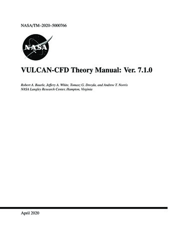
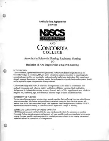
Figure 1. Flow of information for the described simulation framework.representing the final results were extracted and placed in a results file that was readby the framework driver. For the proof-of-concept supersonic facility nozzle designproblem, codes were run sequentially in order to define the nozzle profile, generatethe three-dimensional numerical grid, run the CFD analysis, and extract the resultsthat were fed back to the framework driver in order to record results and assignvalues to the design variables for subsequent iterations. The diagram in fig. 1 mapsto the following discussion in order to visualize the flow of information from onecode to the next.Non-dimensionalized, two-dimensional nozzle profiles were generated using acode written by Richard Ga ney of the Hypersonic Airbreathing Propulsion Branchat NASA Langley Research Center. The IMOCND code1 uses an MOC procedureto design an inviscid nozzle profile given input parameters such as target nozzle exitMach number and non-dimensional throat radius of curvature. Because the methodproduces non-dimensionalized nozzle profiles, the resulting nozzle wall contour wasscaled such that the exit height matched the design requirement.Final nozzle wall profile definition and grid generation were completed via acustom script that took as input the nozzle wall profile from the IMOCND codeand produced a three dimensional computational grid along the entire nozzle lengthfrom the subsonic inflow to the supersonic exit. The profile was scaled given auser-defined exit size and the subsonic nozzle contour was curve fit to the subsonicentry point in order to achieve a fixed nozzle entrance wall angle. Grid spacing wasdefined by a user-specified number of longitudinal and transverse points as well asclustering parameters near the walls and near the throat.2 Clustering was enforcedto achieve sufficient resolution in the wall boundary layer as well as in areas whererapid area changes occur.The nozzle flow properties were simulated using the VULCAN-CFD3,4 code, developed and maintained at NASA Langley Research Center. VULCAN-CFD uses a5
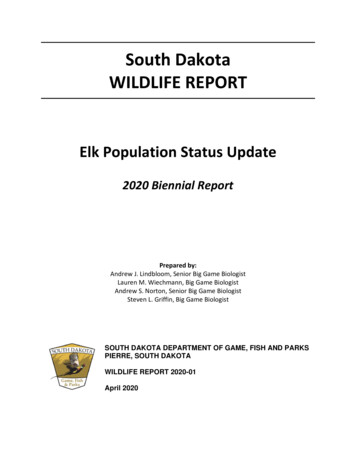
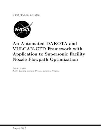
Figure 2. A notional schematic is shown of the definition of the core flow area inthe nozzle exit. The core area is defined here as the largest rectagular area that fitscompletely within the region of flow outside of the boundary layer.finite-volume, cell-centered scheme for solving flows on structured grids. The nozzleflow for this study was assumed to be viscous, thermally perfect, and chemicallyfrozen with non-vititated air. The flow fluxes were computed using LDFSS5 andwere recombined with a 3rd order MUSCL interpolation strategy. The flow wasintegrated temporally using the ILU scheme6 with local time stepping and an increasing CFL number schedule. Turbulence was modeled using the two-equationMenter k-! model7 with a turbulent Prandtl number of 0.9. Wall matching functions8 were used for wall-bounded areas of the solution domain to relax boundarylayer grid resolution requirements. Finally, a coarse, medium, and fine grid sequencing technique was used to speed up the time required for solution convergence.Solution quantities of interest were extracted from the VULCAN-CFD flow fieldusing Tecplot . At the conclusion of each simulation, the exit plane data fromthe nozzle was extracted and exported to a data file that was read and processedby a custom script. Regions in the plane where the exit flow Mach number werewithin 1% of the design Mach number were identified so that the core size couldbe determined as an engi
TECHNICAL TRANSLATION. English-language translations of foreign scientific and technical material pertinent to NASA’s mission. Specialized services also include organizing and publishing research results, distributing specialized research announcements and feeds, providing information desk and personal search support, and enabling data exchange services. For more information about the .