Transcription
Technical BriefingSoftware TechnologyIEC 61508: Know your SILs from your elbowWorking with the programmable electroniccomponents sectorwww.ldra.com* Registration required to download the document LDRA Ltd. This document is property of LDRA Ltd. Its contents cannot be reproduced, disclosed or utilised without company approval.LDRA Ltd1IEC 61508: Know your SILs from your elbow
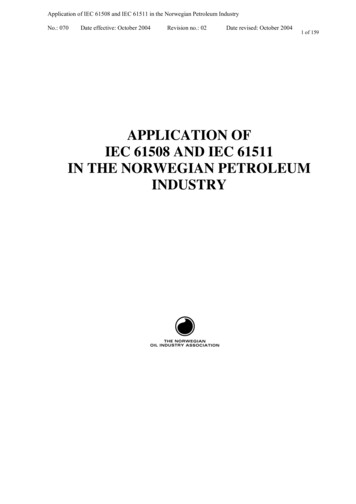
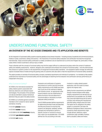
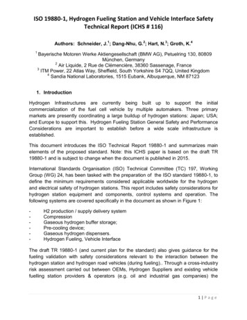
IntroductionWith recent advances in automation, software is no longer a bit-part contributor to electro-mechanicalsystems but is now the underlying technology providing functional safety for products in many marketsegments. The requirement for software functional safety has therefore become a critical topic inindustrial automation, transportation, nuclear energy generation and other markets. IEC 61508:2010“Functional safety of electrical/electronic/programmable electronic safety-related systems” is widelyaccepted as a reference standard. The generic nature of IEC 61508 makes it an ideal “blank canvas” forthe seamless integration of application dependent factors, and hence the derivation of industry andsector specific standards.This briefing describes the key software development and verification process requirements of the IEC61508 standard and how automated tools such as the LDRA tool suite and its component parts canassist with meeting them. It is structured to mirror the flow suggested by the V-model described by thestandard.Safety Integrity LevelsEmbedded software developers will be primarily concerned with part 3 of IEC 61508:20101, “SoftwareRequirements”. However, the level of effort required to complete each objective in the standard isdependent on the Safety Integrity Level (or “SIL”) of the safety functions implemented by the system.The derivation of the SIL is covered in more detail in part 52 of the standard, “Examples of methods forthe determination of safety integrity levels”.Annex A of that standard discusses the concept of “Necessary risk reduction”3. Tolerable risk isdependent on such as the severity of injury, the number of people exposed to danger, and the frequencyand duration of that exposure.The standard goes on to define Safety Integrity as “ the probability of a safety-related systemsatisfactorily performing the required safety functions under all the stated conditions within a statedperiod of time”4. “Systematic Safety Integrity” is the subsection concerning software applications.The SIL assigned to each safety function therefore depends the probability of failure, which can bederived in several different ways. The higher the probability of failure, the higher the SIL (from SIL 1 toSIL 4), and the more demanding the overheads on software development to make the risk acceptable.The Software Development LifecycleFigure 1 shows the V-model illustration from the standard, superimposed with an illustration of how theLDRA tool suite and other complementary tools can be applied within the process.IEC 61508 is not only a stand-alone standard. It also forms the basis for complete, industry-specificderivative standards such as ISO 262625 for the automotive industry, and is also frequently referencedpiecemeal when its generic objectives are applicable to more narrowly defined sectors. One suchexample is the IEC 13849:2015 for control system software, which defers to the development cycle of IEC61508 for the most critical applications it describes.Part 3 of the standard, “Software Safety Lifecycle Requirements”, structures the development of thesoftware in defined phases and activities to reflect and subdivide the phases illustrated in this V-modeldiagram. There are also 7 Annexes defined in IEC 61508:2010-3 which are referenced by the main body ofthe standard. Annex A is discussed in the body of this paper.1IEC 61508:2010-3, Functional safety of electrical/electronic/programmable electronic safety-relatedsystems – Part 3: Software RequirementsIEC 61508:2010-5, Functional safety of electrical/electronic/programmable electronic safety-relatedsystems – Part 5: Examples of methods for thedetermination of safety integrity levels3IEC 61508:2010-5, Annex A, Section A.2, “Necessary risk reduction”4IEC 61508:2010-5, Annex A, Section A.4 - Safety Integrity5ISO 26262:2011, Road vehicles – Functional safety2LDRA Ltd2IEC 61508: Know your SILs from your elbow
Figure 1: Mapping the capabilities of the LDRA tool suite and complementary tools to the IEC 61508:2010development lifecycle (the V-model)6IEC 61508:2010-3 Section 7.2: “Software safety requirements specification”The first step in the IEC 61508:2010 V-model concerns the definition of a software safety requirementsspecification. Section 7.2 highlights the objectives associated with the specification of software safetyrequirements. These include the derivation of requirements for the software safety functions, thesoftware systematic capability, and the implementation of the required safety functions.The V-model illustrates the need for each step in the process to be traceable to the next, as implied bythe verification arrows during the lifecycle, and the validation step at its end. Bi-directional traceability isspecified as an explicit objective in the Annex A.1 table.Achieving a format that lends itself to bi-directional traceability will help to achieve compliance withthe standard. Bigger projects, perhaps with contributors in geographically diverse locations, arelikely to benefit from an application lifecycle management tool such as IBM Rational DOORS 7,Siemens , Polarion PLM 8, Jama Connect 9, or more generally, similar tools offering support forstandard Requirements Interchange Formats10. Smaller projects can cope admirably with carefullyworded Microsoft Word or Microsoft Excel documents, written to facilitate links up and down thedevelopment process model.Bi-directional traceabilityIt would be easy to dismiss the task of tracing between the development lifecycle phases as trivial, buttheir combined effect on project management overhead can be significant.6Based on IEC 61508:2010-3 Figure 6 – Software systematic capability and the development lifecycle (the org/spec/ReqIF/7LDRA Ltd3IEC 61508: Know your SILs from your elbow
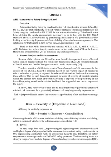
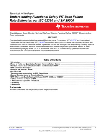
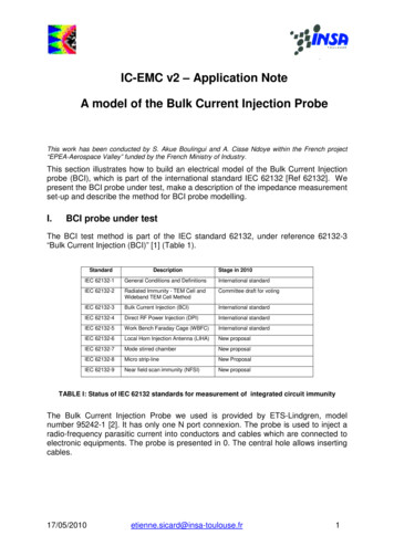
For instance, consider an unexpected change of requirement imposed by a customer. What is impacted?Which requirements? What elements of the code design? What code needs to be revised? And which partsof the software will require re-testing?In general terms, the most effective way to ensure that any project is not thrown off course by sucheventualities is to maintain Bidirectional Traceability of Requirements11 (Figure 2) to confirm that all outlinerequirements have been completely addressed, that all detailed requirements can be traced to outlinerequirements, and that there are spurious work products that are surplus to requirements.IEC 61508 demands adherence to this principle.Figure 2: An Illustration of the principles ofBidirectional TraceabilityRequirements rarely remain unchangedthroughout the lifetime of a project, and that canturn the maintenance of the resulting traceabilitymatrix into an administrative nightmare.Furthermore, connected systems extend thatheadache into the maintenance phase, requiringrevision whenever a vulnerability is exposed.Automating the tracing of requirements alleviatesthis concern by automatically maintaining the connections between the requirements, development,and testing artefacts and activities. Any changes in the associated documents or software code areautomatically highlighted such that any consequential re-testing can be dealt with accordingly (Figure 3).Figure 3: The Uniview graphic from the TBmanager component of the LDRA tool suite, showing how therelationships between tests and requirements can be ne/westfall-bidirectional.pdf Bidirectional Requirements Traceability, Linda WestfallLDRA Ltd4IEC 61508: Know your SILs from your elbow
IEC 61508:2010-3 Section 7.3: “Validation plan for software aspects of system safety”This section of the standard is focused on the planning of when, where, how and by whom verificationand validation activities are to be carried out, as they relate to system safety. It requires consideration ofwhether these activities are to be manually or automatically implemented, but the more detailed definition ofrequirements for the tools themselves are not considered until later in the lifecycle.IEC 61508:2010-3 Section 7.4.3: “Requirements for software architecture design”This section references tables that specify where fault detection techniques need to be implemented as partof the software architecture, such as fault detection, error detection and failure assertion programming.These techniques are designed to highlight failures, thus providing the basis for counter-measures in orderto minimize their consequences.Static analysis techniques can be used to confirm that these sound design objectives are reflected in thecode. Examples include Structured Programming Verification (used to identify unstructured code which maylead to erroneous behaviour of the application) and the generation of complexity metrics such as CyclomaticComplexity and Halstead’s metrics (used to help determine the software module size, software complexityand the data flow information). This confirmation of implemented objectives also reflects the need forbidirectional traceability as highlighted in IEC 61508:2010-7 Section C.2.11 “Traceability”.IEC 61508:2010-3 Section 7.4.4: “Requirements for support tools, including programminglanguages”This section discusses the selection of the programming language(s) to be used and the associated toolchain for the development of that code, including verification and validation tools (section 7.4.4.2), staticcode analysers, test coverage monitors and configuration management tools.IEC 61508:2010-7 Section C.4.5 “Suitable programming languages” recommends that “The programminglanguage chosen should lead to an easily verifiable code with a minimum of effort and facilitate programdevelopment, verification and maintenance.”Features which make verification difficult and therefore should be avoided include recursion, any type ofdynamic variables or objects, and multiple entries or exits of loops, blocks or subprograms.Static analysis techniques provide automated facilities to check compliance with the programming standardssuch as MISRA and CERT C which are designed to prevent the introduction of vulnerabilities or latent errorsin source code. Such coding standards usually explicitly disallow the use of the programming featuresidentified above, and adherence to these coding standards can be checked automatically (Figure 4).Figure 4: Adherence to coding standards” guidelines can be checked automaticallyby LDRA’s static analysis toolsTable A.3 from IEC 61508-3 Annex A12 references the need for “certified tools and translators”. In most cases,the most cost effective approach is to use a tool that is already approved for the applied standard by anappropriate TÜV certifying organization.12IEC 61508:2010-3 Annex A, Table A.3, Software design and development – support tools and programming languageLDRA Ltd5IEC 61508: Know your SILs from your elbow
IEC 61508:2010-3 Section 7.4.5: “Requirements for detailed design and development –software system design”This section of the standard specifies design and coding standard enforcement measures pertinent to thesource code, including “completeness with respect to software safety requirements specification” and“correctness with respect to software safety requirements specification”.The “Completeness” and “Correctness” are both reflections of the overriding for bidirectional traceability,and that is most easily managed through the application of a requirements traceability tool. The complexityof application code design can be compared with the complexity of implementation, using static analysisto generate industry standard metrics, and industrial coding standards including MISRA C:201213, MISRAC :200814, SEI CERT C15, and JSF AV16 are designed to limit the use of constructs most likely to introducesuch as common cause failure and unpredictability.IEC 61508:2010-3 Section 7.4.6: “Requirements for code implementation”This is a short section, mostly consisting of an emphasis for the need for traceability. Best practise dictatesthat static and dynamic analysis of the code is an ongoing process while the code is being developed, and sothe code implementation process is interwoven with module and integration testing, as well as ongoing staticanalysis.IEC 61508:2010-3 Section 7.4.7: “Requirements for software module testing” and Section 7.4.8:“Requirements for software integration testing”These sections identify methods designed to contribute to the achievement of software safety. Thecombination of code review and software module testing verifies that a software module satisfies itsassociated specification, and again the standard calls for “completeness” and “correctness” in that regard.Although module testing can be performed by writing custom code for the purpose, the use of a certified,proven test tool is likely to be much more cost effective unless the code base is very small. Such a tool canautomatically generate test drivers and harnesses (wrapper code) with no extra coding or scripting required,enabling tests to be easily and efficiently run on code units (Figure 5). These tests can be subsequentlyregressed, with clear maintenance tracking and seamless storage of test data and results.Figure 5: Performing requirement based unit-testing using the TBrun component of the LDRA tool sui13MISRA C:2012: Guidelines for use of the C language in critical systems, ISBN 978-906400-11-8 (PDF), March 2013MISRA C :2008 - Guidelines for the use of the C language in critical systems, ISBN 978-906400-04-0 (PDF), June 2008.15SEI CERT C Coding Standard, https://wiki.sei.cmu.edu/confluence/display/c/SEI CERT C Coding Standard16JSF AV, JOINT STRIKE FIGHTER AIR VEHICLE C CODING STANDARDS FOR THE SYSTEM DEVELOPMENT AND DEMONSTRATION PROGRAM,Document Number 2RDU00001 Rev C, 2005.14LDRA Ltd6IEC 61508: Know your SILs from your elbow
IEC 61508:2010-3 Section 7.5: “Programmable electronics integration (hardware and software)”It is necessary for the integrated software to be proven on the target programmable electronic hardwareto ensure compatibility and to meet the requirements of the intended safety integrity level, The standardrequires that both functional and “black box” tests are performed to check the dynamic behaviour underreal functional conditionsStructural code coverage analysis can be supported by unit test, system test, or a combination of the two,operating in tandem (Figure 6). For instance, a preferred approach might be to use dynamic system testto generate coverage of most of the source code, and to supplement it using unit tests to exercise codeconstructs which are inaccessible during normal operation.To complete the structural coverage analysis, boundary values could be provided manually or generatedautomatically to check the permissible and inadmissible ranges.Figure 6: Examples of representations of structural coverage within the LDRA tool suiteIEC 61508:2010-3 Section 7.4.6: “Requirements for code implementation”Aside from emphasizing the need for bi-directional traceability, this section is largely a stub, cross-referencing to other sections of the standard.IEC 61508:2010-3 Section 7.7: “Software aspects of system safety validation”This section details how it is to be confirmed that the integrated system complies with the software safetyrequirements specification at the required safety integrity level.During development, automated unit and system testing can be used to confirm that the functions of asystem or program behave as the specification dictates. The associated configuration files can be re-usedfor regression analysis to confirm ongoing adherence to the specified requirements, and hence fulfil therequirements of this validation phase. Automated requirements tracing complements this approach byproviding forward and backward traceability between the software safety requirements specification andsoftware safety validation plan.IEC 61508:2010-3 Section 7.8: “Software modification”Section 7.8 describes how modifications are to be handled, to ensure that the resulting software as awhole retains the quality of the original.LDRA Ltd7IEC 61508: Know your SILs from your elbow
Impact Analysis is a technique used to determine whether a change or an enhancement to a softwaresystem has affected, or has the potential to affect, the existing system. When a change is made and impactanalysis is complete, the extent of the re-verification required will be influenced by the number of softwaremodules affected, the criticality of the affected software modules and the nature of the change. Possibledecisions are Only the changed software module is re-verified All affected software modules are re-verified, or The complete system is re-verifiedClearly such re-verification is much easier to arrange if the tests for the existing tests are stored, and regression test can be automated.The connected system – a new significance for system modificationWith the advent of the connected device and the Internet of Things, system maintenance takes on a newsignificance. For any connected systems, requirements don’t just change in an orderly manner duringdevelopment. They change without warning - whenever some smart Alec finds a new vulnerability,develops a new hack, or compromises the system. And they keep on changing throughout the lifetime ofthe device.For that reason, the ability of next-generation automated management and requirements traceability toolsand techniques to create relationships between requirements, code, static and dynamic analysis results,and unit- and system-level tests is especially valuable for connected systems. Linking these elementsalready enables the entire software development cycle to become traceable, making it easy for teams toidentify problems and implement solutions faster and more cost effectively. But they are perhaps evenmore important after product release, presenting a vital competitive advantage in the ability to respondquickly and effectively whenever security is compromised.Many software modifications will require changes to the existing software functionality – perhaps withregards to additional utilities in the software. In such circumstances, it is important to ensure that anychanges made or additions to the software do not adversely affect the existing code.A requirements traceability tool can help to alleviate this concern by automatically maintaining theconnections between the requirements, development, and testing artefacts and activities. In theexample shown in, suppose that a change is proposed to the System Level requirement “Installation andconfiguration”. The traceability established at development time between requirements, code and testsmean that the tool can show which parts of the code are impacted by the proposed change, as highlightedin the example.Figure 7: Identifying the impact of requirements change with the TBmanager componentof the LDRA tool suiteLDRA Ltd8IEC 61508: Know your SILs from your elbow
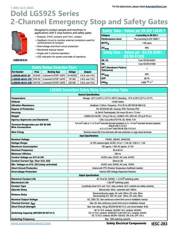
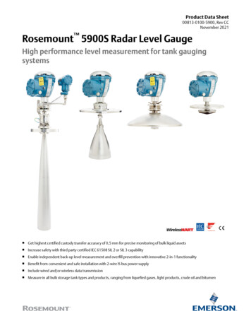
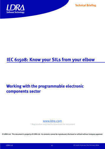
In this scenario, the existing code as launched will also have undergone quality control measures in accordance with the IEC 61508 standard such as static analysis to assess whether coding standards havebeen met, and unit tests to confirm functionality of each code module.In the example shown in Figure 19, a system has been subject to a change request for the “Add products”requirement. Those parts of the system which are potentially affected by the change are easily identifiedby means of a red dot, whereas unaffected functions carry a green dot.Regression Analysis feature can then be used to verify whether the newly introduced or modified moduleshave only affected the functionality of the existing system as intended, or the complete system can be revalidated.IEC 61508:2010-3 Section 7.9: “Software verification”Figure 8 is a reproduction of IEC 61508-3 Table A.9 from the standard, which refers to IEC 61508-3 Section7.9 “Software verification” and IEC 61508-7 Section C.2 “Requirements and detailed design”.IEC 61508-3 Section 7.9 considers generic aspects of verification common to several safety lifecyclephases.Technique/MeasureRefSIL12341Formal proofC.5.12---RRHR2Animation of specification and designC.5.26RRRR3Static analysisB.6.4Table B.8RHRHRHR4Dynamic analysis and testingB.6.5Table B.2RHRHRHR5Forward traceability between the softwaredesign specification and the softwareverification (including data verification) planC.2.11RRHRHR6Backward traceability between the softwareverification (including data verification) plan andthe software design specificationC.2.11RRHRHR7Offline numerical analysisC.2.13RRHRHRSoftware module testing and integrationSee Table A.5Programmable electronics integration testingSee Table A.6Software system testing (validation)See Table A.7”HR” The method is highly recommended for this SIL.“R” The method is recommended for this SIL.“--- “ The method has no recommendation for or against its usage for this SIL.Figure 8:Copy of IEC 61508-3 Table A.917, with techniques and measures supportedby the LDRA tool suite highlighted17IEC 61508-3 Annex A Table A.9 – Software VerificationLDRA Ltd9IEC 61508: Know your SILs from your elbow
ConclusionsWith its many sections, clauses and sub-clauses, IEC 61508 may at first seem intimidating, and its systemof cross-referencing tables in annexes can make it difficult to follow. However, once broken down intodigestible pieces, its principles offer sound guidance in the establishment of a high quality softwaredevelopment process - not only leading up to initial product release but into maintenance and beyond.Such a process is paramount for the assurance of true reliability, quality, safety and effectiveness ofprogrammable electronic components. When supported by a complementary and comprehensive suite oftools for analysis and testing, it can smooth the way for development teams to work together to effectivelydevelop and maintain large projects with confidence in their quality.www.ldra.comLDRA Technology Pvt. Ltd.LDRA UK & WorldwidePortside, Monks Ferry,Wirral, CH41 5LHTel: 44 (0)151 649 9300e-mail: info@ldra.comLDRA Ltd9Unit No B-3, 3rd floor Tower B,Golden Enclave. HAL Airport RoadBengaluru560017IndiaTel: 91 80 4080 8707e-mail: india@ldra.comIEC 61508: Know your SILs from your elbowIEC 61508: Know your SILs from your elbow v2.0 11/18LDRA Technology Inc.2540 King Arthur Blvd, Suite 228Lewisville, Texas 75056United StatesTel: 1 (855) 855 5372e-mail: info@ldra.com
3 IEC 61508:2010-5, Annex A, Section A.2, “Necessary risk reduction” 4 IEC 61508:2010-5, Annex A, Section A.4 - Safety Integrity 5 ISO 26262:2011, Road vehicles – Functional safety LDRA Ltd 2