Transcription
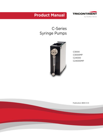
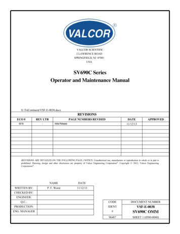
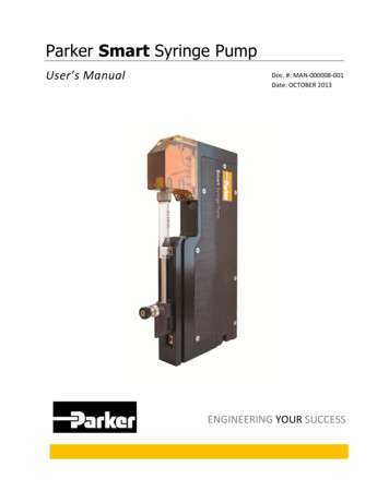
Parker Smart Syringe PumpUser’s ManualDoc. #: MAN-000008-001Date: OCTOBER 2013ENGINEERING YOUR SUCCESS
2013, Parker Hannifin Corporation. All Rights Reserved.DisclaimerAlthough every effort has been taken to ensure the accuracy of this document, it may be necessary, without notice, to makeamendments or correct omissions. Parker Precision Fluidics cannot accept responsibility for damage, injury, or expensesresulting there from.Product Warranty InformationThis warranty comprises the sole and entire warranty pertaining to products described in the Terms and Conditions of sale.Return Materials AuthorizationsHazardous Material: All products returned must be free of hazardous materials. Return of any product exposed to biohazardous material will not be accepted.You must obtain a Return Material Authorization (RMA) number from Parker Precision Fluidics in order that we may processyour returned equipment. Material will not be accepted unless an RMA number is assigned and is clearly marked on allincoming packages and associated paperwork. This policy has been set for our mutual protection in that it greatly reduces thepossibility of misplaced returns. Please call our Customer Service Department at 1-800-525-2857 to obtain an RMA number.Copyright and Trademark InformationCAVRO is a registered trademark of TECAN Systems, Inc.Molex is a registered trademark of Molex Connectors, Inc.EPOS2 is a trademark of Maxon Motor AGULTEM is a registered trademark of SABIC Innovative Plastics IP BVTriContinent is a trademark of TriContinent Scientific, Inc.Smart Syringe Pump User’s Manual, Doc. # MAN-000008-001, Rev. APage 2
Table of ContentsChapter 1 Overview. 141.1Introduction . 141.2Warnings and Special Symbols . 151.3CE Compliance . 161.4Disclaimers . 161.5Handling Procedures . 171.6Pump Features and Options . 17Chapter 2 Hardware Setup. 192.1Unpacking the Smart Syringe Pump . 192.2Syringe Pump Setup . 192.2.1Mounting. 192.2.2Leak Diversion Features . 232.2.3Valve Configuration and Flow Direction . 242.2.4Syringe Barrel Selection . 252.2.5Syringe Barrel/Plunger Installation . 252.2.6Syringe Barrel/Plunger Removal . 292.2.7Fitting and Tubing Installation . 312.2.8Reservoir Requirements. 352.2.9Pressure Limits . 352.2.10Power Requirements. 362.2.11Power and Communications Interface (OEM to Pump). 362.3Multiple Smart Syringe Pump Configuration . 382.3.1CAN Network Terminating Resistor . 39Chapter 3 Communications Interface . 413.13.2Communication Configurations . 413.1.1Workstation (PC) Control . 413.1.2Direct Connection . 42RS-232 Protocol . 43Smart Syringe Pump User’s Manual, Doc. # MAN-000008-001, Rev. APage 3
3.3CANopen Protocol . 433.3.1CAN Bit Rates . 433.3.2Workstation Control with CAN Interface . 443.3.3Direct Connection with CAN Interface . 443.4CAN Addressing Scheme . 45Chapter 4 Operating the Pump Using the Smart Syringe Pump Software. 464.1Getting Started. 464.2Hardware Setup . 464.3Installing the Software . 464.4Starting the Software . 514.5Basic Operation . 524.5.1Homing . 534.5.2Setting Syringe Barrel Size and Replacing Syringe . 554.5.3Aspirate . 554.5.4Dispense . 564.5.5Priming . 574.5.6Manual Priming . 574.6Configuration . 584.6.1Communications Configuration . 594.6.2Pump Configuration . 604.6.3Motor Drive and Syringe Barrel Usage. 604.7Scripting . 604.7.1Synchronous and Asynchronous Operation. 624.7.2Scripting Command Tabs . 624.84.9Diagnostics . 654.8.1Motion Control. 664.8.2Syringe Volume and Calibration. 674.8.3Acceleration, Deceleration and Backlash . 684.8.4Motor Current Display . 69Homing Tab . 69Smart Syringe Pump User’s Manual, Doc. # MAN-000008-001, Rev. APage 4
4.9.1Homing Parameters . 704.9.2Proportional Homing. 714.9.3Pump Unbinding . 714.10Pressure Calculator . 724.11Pump Parameters . 744.11.1Viewing Pump Parameters . 744.11.2Edit Pump Parameters Dialog . 774.11.3Resetting Pump Parameters . 784.11.4Changing Pump Current Limits . 784.11.5Changing Pump Usage and Syringe Usage . 794.11.6Changing the Pump Node Address . 794.11.7Changing the Pump RS-232 Baud Rate . 814.11.8Changing the Pump CAN Bit Rate . 834.12Error Handling and Error History . 844.13Removing the Software . 85Chapter 5 Smart Syringe Pump Library . 875.1Smart Syringe Pump Library Overview . 875.1.1Library Files . 875.1.2Using the Smart Syringe Pump Library. 885.1.3Object Browser. 895.2Basic Operation with the Smart Syringe Pump Library. 905.2.1Connection . 915.2.2Homing . 915.2.3Set Valve Position. 935.2.4Set Syringe Size . 945.2.5Set Speed. 955.2.6Aspirate . 965.2.7Dispense . 975.2.8Unitialize . 985.2.9Changing the Pump Node Address . 98Smart Syringe Pump User’s Manual, Doc. # MAN-000008-001, Rev. APage 5
5.2.10Changing the Pump RS-232 Baud Rate . 995.2.11Changing the Pump CAN Bit Rate . 995.3Scripting Operation with the Smart Syringe Pump Library . 995.3.15.4Scripting Response Handler . 100Pump Status and Error Handling. 1015.4.1Pump Connection . 1015.4.2Pump Status . 1015.4.3Error Handling . 1025.4.4Advanced Error Handling . 1035.5Library Functions and Properties . 1045.5.1PumpConnection. 1045.5.2PumpControl . 1125.5.3LimitValues . 1335.5.4Error Data . 136Chapter 6 Scripting Commands. 1386.1Command Syntax . 1386.2Pump Control . 1386.3Program Flow Control . 1436.4Pump Configuration . 1446.5Reporting Commands . 1456.6Error Codes and Status Byte . 1466.7Unsupported Standard Commands . 147Chapter 7 System Integration Using a Direct Connection . 1517.1Overview . 1517.2Initialization . 1517.3RS-232 Protocol . 1527.4CAN Protocol . 1527.5Operating Commands . 1527.5.1Homing . 1527.5.2Aspirate and Dispense. 154Smart Syringe Pump User’s Manual, Doc. # MAN-000008-001, Rev. APage 6
7.5.3Valve Position . 1557.5.4Shutdown . 1557.6Pump Status and Error Handling. 1567.6.1Pump Status . 1567.6.2Error Handling . 157Chapter 8 Syringe Pump Parameters . 1588.1Motor Parameters . 1588.1.1Acceleration and Deceleration. 1588.1.2Backlash. 1598.1.3Homing Parameters . 1618.1.4Current Limits. 1628.2Smart Syringe Pump Limits and Constants . 1638.3Syringe Calibration . 1658.3.1Determining Calibration Value . 165Chapter 9 Maintenance and Cleaning. 1679.1Preventative Maintenance and Cleaning . 1679.2Manifold and Valve Replacement . 1689.3EPOS2 Motion Controller and Interface PCB Replacement . 1739.3.1Replacing the EPOS2 Motion Controller . 1739.3.2Replacing the Interface PCB . 176Chapter 10 Troubleshooting . 17810.1Troubleshooting Guide . 17810.2Pump Status Indicator LED. 18710.3Smart Syringe Pump Error Messages . 188Chapter 11 Ordering Information . 19511.1Contact Information. 19511.2Available Configurations . 19511.3Accessories. 19611.3.1Syringe Barrels . 19611.3.2Compatible Syringe Barrels . 196Smart Syringe Pump User’s Manual, Doc. # MAN-000008-001, Rev. APage 7
11.3.3Accessories and Replacement Parts List . 197Chapter 12 Appendix. 19812.1Performance Specifications . 19812.1.1Fluidic . 19812.1.2Mechanical . 19812.1.3Reliability . 19912.1.4Electrical . 19912.1.5Communications . 19912.1.6Environmental . 20012.1.7Operating Shock and Vibration . 20012.1.8Physical Characteristics . 20012.1.9Regulatory Compliance . 20112.1.10Chemical Compatibility . 20112.2Outline Drawing . 20312.3Calculations . 20312.3.1Pressure Calculation. 20312.3.2Move Time Calculations . 204Smart Syringe Pump User’s Manual, Doc. # MAN-000008-001, Rev. APage 8
List of FiguresFigure 1.1 Smart Syringe Pump . 14Figure 2.1 Mounting Holes . 20Figure 2.2 Recommended Vertical Mounting Orientations . 21Figure 2.3 Vertical Mounting Angle . 21Figure 2.4 Recommended Horizontal Mounting Orientations . 22Figure 2.5 Mounting Orientations Not Recommended . 22Figure 2.6 Leak Zones . 23Figure 2.7 Leak Diversion Ports . 24Figure 2.8 Valve and Manifold Port Identification . 24Figure 2.9 Retaining Screw and Locking Nut . 26Figure 2.10 Plunger Button Saddle . 26Figure 2.11 Installing Syringe Barrel to Manifold. 27Figure 2.12 Syringe Barrel Secured to Pump . 28Figure 2.13 Syringe Hub Set Screw . 29Figure 2.14 Removing the Syringe Barrel from the Manifold . 30Figure 2.15 Removing the Syringe Barrel from the Syringe Button Clasp . 31Figure 2.16 Tubing through Nut . 32Figure 2.17 Ferrule Installation . 32Figure 2.18 Fitting Assembly Preparation . 32Figure 2.19 Fitting to Reservoir Port Installation . 33Figure 2.20 Fitting to Normally Open or Aspirate / Dispense Port . 34Figure 2.21 Reservoir Tube Routing . 34Figure 2.22 Reservoir Tube Through P-Clamp . 35Figure 2.23 Power and Communications Interface OEM to Pump . 36Figure 2.24 Power and RS-232 Communications Pump Cable Detail . 37Figure 2.25 CAN Wiring Diagram . 38Figure 2.26 Multiple Smart Syringe Pump Wiring Diagram . 39Figure 2.27 CAN Bus Terminating Resistor R1 . 40Figure 3.1 Smart Syringe Pump using Workstation Control . 41Smart Syringe Pump User’s Manual, Doc. # MAN-000008-001, Rev. APage 9
Figure 3.2 Smart Syringe Pump using OEM Embedded Controller . 42Figure 4.1 InstallShield Wizard Welcome Screen. 47Figure 4.2 License Agreement Window . 48Figure 4.3 Choose Destination Location Window . 49Figure 4.4 Start Copying Files Window . 50Figure 4.5 Installation Complete Window . 51Figure 4.6 Smart Syringe Pump Software . 52Figure 4.7 Pump Status Panel . 54Figure 4.8 Homing on the Operation Tab . 54Figure 4.9 Syringe Barrel Size and Replacement. 55Figure 4.10 Aspirate on the Operation Tab . 56Figure 4.11 Dispense on the Operation Tab . 56Figure 4.12 Prime on the Operation Tab . 57Figure 4.13 Manual Syringe Priming . 58Figure 4.14 Configuration Tab. 59Figure 4.15 Scripting Tab. 61Figure 4.16 Basic Commands . 63Figure 4.17 Additional Commands . 63Figure 4.18 Smart Syringe Pump Commands. 64Figure 4.19 Queries .
Parker Smart Syringe Pump User's Manual Doc. #: MAN-000008-001 Date: OCTOBER 2013 ENGINEERING YOUR SUCCESS
