Transcription
BGT24AT2Silicon Germanium 24 GHz Transmitter MMICData SheetRevision 3.2, 2016-01-20FinalRF & Protection Devices
Edition 2016-01-20Published byInfineon Technologies AG81726 Munich, Germany 2016 Infineon Technologies AGAll Rights Reserved.Legal DisclaimerThe information given in this document shall in no event be regarded as a guarantee of conditions orcharacteristics. With respect to any examples or hints given herein, any typical values stated herein and/or anyinformation regarding the application of the device, Infineon Technologies hereby disclaims any and all warrantiesand liabilities of any kind, including without limitation, warranties of non-infringement of intellectual property rightsof any third party.InformationFor further information on technology, delivery terms and conditions and prices, please contact the nearestInfineon Technologies Office (www.infineon.com).WarningsDue to technical requirements, components may contain dangerous substances. For information on the types inquestion, please contact the nearest Infineon Technologies Office.Infineon Technologies components may be used in life-support devices or systems only with the express writtenapproval of Infineon Technologies, if a failure of such components can reasonably be expected to cause the failureof that life-support device or system or to affect the safety or effectiveness of that device or system. Life supportdevices or systems are intended to be implanted in the human body or to support and/or maintain and sustainand/or protect human life. If they fail, it is reasonable to assume that the health of the user or other persons maybe endangered.
BGT24AT2Silicon Germanium 24 GHz Transmitter MMICBGT24AT2 Silicon Germanium 24 GHz Transmitter MMICRevision History: 2016-01-20, Revision 3.2Previous Revision: 2015-04-27 Revision 3.1PageSubjects (major changes since last revision)Trademarks of Infineon Technologies AGAURIX , BlueMoon , C166 , CanPAK , CIPOS , CIPURSE , COMNEON , EconoPACK , CoolMOS ,CoolSET , CORECONTROL , CROSSAVE , DAVE , EasyPIM , EconoBRIDGE , EconoDUAL ,EconoPIM , EiceDRIVER , eupec , FCOS , HITFET , HybridPACK , I²RF , ISOFACE , IsoPACK ,MIPAQ , ModSTACK , my-d , NovalithIC , OmniTune , OptiMOS , ORIGA , PRIMARION ,PrimePACK , PrimeSTACK , PRO-SIL , PROFET , RASIC , ReverSave , SatRIC , SIEGET ,SINDRION , SIPMOS , SMARTi , SmartLEWIS , SOLID FLASH , TEMPFET , thinQ! ,TRENCHSTOP , TriCore , X-GOLD , X-PMU , XMM , XPOSYS .Other TrademarksAdvance Design System (ADS) of Agilent Technologies, AMBA , ARM , MULTI-ICE , KEIL ,PRIMECELL , REALVIEW , THUMB , µVision of ARM Limited, UK. AUTOSAR is licensed by AUTOSARdevelopment partnership. Bluetooth of Bluetooth SIG Inc. CAT-iq of DECT Forum. COLOSSUS ,FirstGPS of Trimble Navigation Ltd. EMV of EMVCo, LLC (Visa Holdings Inc.). EPCOS of Epcos AG.FLEXGO of Microsoft Corporation. FlexRay is licensed by FlexRay Consortium. HYPERTERMINAL ofHilgraeve Incorporated. IEC of Commission Electrotechnique Internationale. IrDA of Infrared DataAssociation Corporation. ISO of INTERNATIONAL ORGANIZATION FOR STANDARDIZATION. MATLAB ofMathWorks, Inc. MAXIM of Maxim Integrated Products, Inc. MICROTEC , NUCLEUS of Mentor GraphicsCorporation. Mifare of NXP. MIPI of MIPI Alliance, Inc. MIPS of MIPS Technologies, Inc., USA. muRata of MURATA MANUFACTURING CO., MICROWAVE OFFICE (MWO) of Applied Wave Research Inc.,OmniVision of OmniVision Technologies, Inc. Openwave Openwave Systems Inc. RED HAT Red Hat, Inc.RFMD RF Micro Devices, Inc. SIRIUS of Sirius Satellite Radio Inc. SOLARIS of Sun Microsystems, Inc.SPANSION of Spansion LLC Ltd. Symbian of Symbian Software Limited. TAIYO YUDEN of Taiyo YudenCo. TEAKLITE of CEVA, Inc. TEKTRONIX of Tektronix Inc. TOKO of TOKO KABUSHIKI KAISHA TA.UNIX of X/Open Company Limited. VERILOG , PALLADIUM of Cadence Design Systems, Inc. VLYNQ of Texas Instruments Incorporated. VXWORKS , WIND RIVER of WIND RIVER SYSTEMS, INC. ZETEX ofDiodes Zetex Limited.Last Trademarks Update 2010-10-26Final Data Sheet3Revision 3.2, 2016-01-20
BGT24AT2Silicon Germanium 24 GHz Transmitter MMICTable of ContentsTable of ContentsTable of Contents . . . . . . . . . . . . . . . . . . . . . . . . . . . . . . . . . . . . . . . . . . . . . . . . . . . . . . . . . . . . . . . . 4List of Figures . . . . . . . . . . . . . . . . . . . . . . . . . . . . . . . . . . . . . . . . . . . . . . . . . . . . . . . . . . . . . . . . . . . 5List of Tables . . . . . . . . . . . . . . . . . . . . . . . . . . . . . . . . . . . . . . . . . . . . . . . . . . . . . . . . . . . . . . . . . . . . 61Features . . . . . . . . . . . . . . . . . . . . . . . . . . . . . . . . . . . . . . . . . . . . . . . . . . . . . . . . . . . . . . . . . . . . . . . . 722.12.22.32.42.52.62.72.82.9Electrical Characteristics . . . . . . . . . . . . . . . . . . . . . . . . . . . . . . . . . . . . . . . . . . . . . . . . . . . . . . . . . . 9Absolute Maximum Ratings . . . . . . . . . . . . . . . . . . . . . . . . . . . . . . . . . . . . . . . . . . . . . . . . . . . . . . . . . 9ESD Integrity . . . . . . . . . . . . . . . . . . . . . . . . . . . . . . . . . . . . . . . . . . . . . . . . . . . . . . . . . . . . . . . . . . . . 10Power Supply . . . . . . . . . . . . . . . . . . . . . . . . . . . . . . . . . . . . . . . . . . . . . . . . . . . . . . . . . . . . . . . . . . . 11VCO . . . . . . . . . . . . . . . . . . . . . . . . . . . . . . . . . . . . . . . . . . . . . . . . . . . . . . . . . . . . . . . . . . . . . . . . . . 11Frequency Divider . . . . . . . . . . . . . . . . . . . . . . . . . . . . . . . . . . . . . . . . . . . . . . . . . . . . . . . . . . . . . . . . 13TX and LO PGA . . . . . . . . . . . . . . . . . . . . . . . . . . . . . . . . . . . . . . . . . . . . . . . . . . . . . . . . . . . . . . . . . 14Temperature Sensor . . . . . . . . . . . . . . . . . . . . . . . . . . . . . . . . . . . . . . . . . . . . . . . . . . . . . . . . . . . . . . 15Output Level Detector . . . . . . . . . . . . . . . . . . . . . . . . . . . . . . . . . . . . . . . . . . . . . . . . . . . . . . . . . . . . . 16Sensor Multiplexer . . . . . . . . . . . . . . . . . . . . . . . . . . . . . . . . . . . . . . . . . . . . . . . . . . . . . . . . . . . . . . . 163Pin Description . . . . . . . . . . . . . . . . . . . . . . . . . . . . . . . . . . . . . . . . . . . . . . . . . . . . . . . . . . . . . . . . . 174SPI . . . . . . . . . . . . . . . . . . . . . . . . . . . . . . . . . . . . . . . . . . . . . . . . . . . . . . . . . . . . . . . . . . . . . . . . . . . 215Sensor Multiplexer . . . . . . . . . . . . . . . . . . . . . . . . . . . . . . . . . . . . . . . . . . . . . . . . . . . . . . . . . . . . . . 246LO Logic . . . . . . . . . . . . . . . . . . . . . . . . . . . . . . . . . . . . . . . . . . . . . . . . . . . . . . . . . . . . . . . . . . . . . . 257Package Dimensions . . . . . . . . . . . . . . . . . . . . . . . . . . . . . . . . . . . . . . . . . . . . . . . . . . . . . . . . . . . . 26Final Data Sheet4Revision 3.2, 2016-01-20
BGT24AT2Silicon Germanium 24 GHz Transmitter MMICList of FiguresList of FiguresFigure 1Figure 2Figure 3Figure 4Figure 5Figure 6BGT24AT2 Block Diagram . . . . . . . . . . . . . . . . . . . . . . . . . . . . . . . . . . . . . . . . . . . . . . . . . . . . . . . . 8Block Diagram Frequency Divider . . . . . . . . . . . . . . . . . . . . . . . . . . . . . . . . . . . . . . . . . . . . . . . . . 13Timing Diagram of the SPI . . . . . . . . . . . . . . . . . . . . . . . . . . . . . . . . . . . . . . . . . . . . . . . . . . . . . . . 23Package Outline (Top, Side and Bottom View) of VQFN32-9 . . . . . . . . . . . . . . . . . . . . . . . . . . . . 26Marking Layout VQFN32-9 . . . . . . . . . . . . . . . . . . . . . . . . . . . . . . . . . . . . . . . . . . . . . . . . . . . . . . . 26Tape of VQFN32-9 . . . . . . . . . . . . . . . . . . . . . . . . . . . . . . . . . . . . . . . . . . . . . . . . . . . . . . . . . . . . . 26Final Data Sheet5Revision 3.2, 2016-01-20
BGT24AT2Silicon Germanium 24 GHz Transmitter MMICList of TablesList of TablesTable 1Table 2Table 3Table 4Table 5Table 6Table 7Table 8Table 9Table 10Table 11Table 12Table 13Table 14Table 15Table 16Table 17Absolute Maximum Ratings, TA -40 C to 125 C; all voltages with respect to ground, positivecurrent flowing into pin (unless otherwise specified) 9ESD Integrity . . . . . . . . . . . . . . . . . . . . . . . . . . . . . . . . . . . . . . . . . . . . . . . . . . . . . . . . . . . . . . . . . 10Electrical Characteristics, TA -40 C . 125 C, positve current flowing into pin (unless otherwisespecified). 11Electrical Characteristics, , VCC 3.135 V to 3.465 V, TA -40 C to 125 C, PGA output power Pmax, all voltages with respect to ground, positive current flowing into pin (unless otherwise specified),parameters specified in the frequency range from 24 GHz to 24.25 GHz including matchingstructures and a package footprint provided by Infineon using the high frequency laminate Rogers4350B (see Application Note AN359) 11Frequency Divider Truth Table . . . . . . . . . . . . . . . . . . . . . . . . . . . . . . . . . . . . . . . . . . . . . . . . . . . 13Electrical Characteristics, VCC 3.135 V to 3.465 V, TA -40 C to 125 C,VCO frequency 24.0 to 24.25 GHz, divider division ratio 1024, all voltages with respect to ground(unless otherwise specified). 13Electrical Characteristics, VCC 3 .135 V to 3.465 V, TA -40 C to 125 C, PGA output power Pmax , positive current flowing into pin (unless otherwise specified), parameters specified in thefrequency range from 24 GHz to 24.25 GHz include matching structures and a package footprintprovided by Infineon using the high frequency laminate Rogers 4350B (see Application Note AN359).Reference board losses and 2.92 mm connector loss deembedded to outer trafo edge (referenceplane). 14Electrical Characteristics, VCC 3.3 V, TA -40 C to 125 , application and MMIC external circuitacc. to Application Note AN359, all voltages with respect to ground (unless otherwise specified). 15Electrical Characteristics, VCC 3.135 V to 3.465 V, TA -40 C to 125 C, application and MMICexternal circuit acc. to Application Note AN359, all voltages with respect to ground (unless otherwisespecified) 16Electrical Characteristics, VCC 3.135 V to 3.465 V, TA -40 C to 125 C, application and MMICexternal circuit acc. to Application Note AN359, all voltages with respect to ground (unless otherwisespecified) 16Pin Definition and Function . . . . . . . . . . . . . . . . . . . . . . . . . . . . . . . . . . . . . . . . . . . . . . . . . . . . . . 17I/O internal circuits . . . . . . . . . . . . . . . . . . . . . . . . . . . . . . . . . . . . . . . . . . . . . . . . . . . . . . . . . . . . . 18SPI Data Bit Description . . . . . . . . . . . . . . . . . . . . . . . . . . . . . . . . . . . . . . . . . . . . . . . . . . . . . . . . 21SPI Interface . . . . . . . . . . . . . . . . . . . . . . . . . . . . . . . . . . . . . . . . . . . . . . . . . . . . . . . . . . . . . . . . . 23Specification for SPI pins . . . . . . . . . . . . . . . . . . . . . . . . . . . . . . . . . . . . . . . . . . . . . . . . . . . . . . . . 24Truth Table AMUX . . . . . . . . . . . . . . . . . . . . . . . . . . . . . . . . . . . . . . . . . . . . . . . . . . . . . . . . . . . . . 24Truth Table LO Logic . . . . . . . . . . . . . . . . . . . . . . . . . . . . . . . . . . . . . . . . . . . . . . . . . . . . . . . . . . . 25Final Data Sheet6Revision 3.2, 2016-01-20
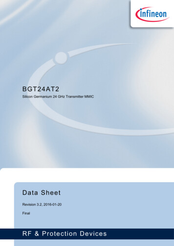
Silicon Germanium 24 GHz TransmitterMMIC1 BGT24AT2Features24 GHz signal source with 2 transmitter outputs and 1 local oscillatoroutputExternal / internal phase inversion and RF pulsing capabilityProgrammable gain amplifiers (PGA) with 6 bit resolutionFully integrated low phase noise VCOFrequency divider with 23.5 MHz outputOn chip RF output level and temperature sensorsMultiplexed output of analog sensor signalsSingle ended RF terminalsSingle supply voltage 3.3 VLow power consumption 775 mW typ.200 GHz bipolar SiGe:C technology b7hf200Fully ESD protected deviceVQFN-32-9 leadless plastic package including lead-tip-inspection (LTI) featurePb-free (RoHS compliant) packageAEC Q100 qualifiedDescriptionThe BGT24AT2 is a low phase noise 24 GHz ISM band multifunction signal source, manufactured in a monolithicSilicon Germanium semiconductor process technology.It accommodates a 24 GHz fundamental voltage controlled oscillator and a frequency divider with a division ratioof 1024. The frequency divider output is differential.The three individual RF outputs generate a typical output power of 10 dBm, adjustable via SPI-programmable 6bit DAC’s. Fast pulsing and phase inversion of the transmit signal is provided either using dedicated control inputsor the 64 bit SPI. Automatic configuration of the LO-output is possible using a dedicated logic.RF output level sensors as well as a temperature sensor are implemented for monitoring purposes. The analogsensor signals along with an additional optional analog input are multiplexed to one common output.The MMIC is manufactured in a 200 GHz, 0.18μm SiGe:C technology and is packaged in a 32 pin leadless RoHScompliant VQFN package with LTI feature.Product 2Final Data Sheet7Revision 3.2, 2016-01-20
BGT24AT2Silicon Germanium 24 GHz Transmitter MMICANA INAMUXTemp.SensorLO ONPH LOLOANA OUTFeaturesSPI DISPI CLKSPI ENSPI64bitBalunSPI DODAC6bitPGALOPH TX2TX2 ONDAC6bitBalunTX2PGATX2PH TX1TX1 ONDAC6bit0/180 0/180 LOLogic0/180 BUF2PGATX1BalunTX1BUF1f-DivVCC/1024VTUNE CVTUNE FDIVDIVXDIV DIS OUTFigure 1VCC VCODAC6bitVEEVEE VCOBlock Diagram BGT 24AT2.vsdBGT24AT2 Block DiagramFinal Data Sheet8Revision 3.2, 2016-01-20
BGT24AT2Silicon Germanium 24 GHz Transmitter MMICElectrical Characteristics2Electrical Characteristics2.1Absolute Maximum RatingsTable 1Absolute Maximum Ratings, TA -40 C to 125 C; all voltages with respect to ground, positivecurrent flowing into pin (unless otherwise specified)ParameterSymbolValuesUnit Test Note / Test ConditionMin.Typ.Max.VCC-0.3–Vcc 0.3 V –Voltage applied to none-RF pinsVIO-0.3–Vcc 0.3 V –DC voltage at RF pinsVDCRF––0V MMIC provides shortcircuit to GND for TX1,TX2 and LO pinsDC voltage at pins VTUNE F,VTUNE CVTUNE-0.3–Vcc 0.3 V –DC voltage at pins DIV, DIVXVDIVIDER 2–Vcc 0.3 V –Total power dissipationPDISS––1000mW –Junction temperatureTJ-40–170 C –Ambient temperature rangeTA-40–125 C TA temperature atpackage soldering pointStorage temperature rangeTSTG-50–125 C –Supply voltage1)1) For SPI EN, SPI DI, SPI CLK the applied voltage may exceed given ratings als long as current into these pins is limitedto ISPI 1 mAAttention: Stresses exceeding the maximum values listed here may cause permanent damage to thedevice. Exposure to absolute maximum rating conditions for extended periods of time mayaffect device reliability. Maximum ratings are absolute ratings; exceeding only one of thesevalues may cause irreversible damage to the integrated circuit.Attention: Integrated protection functions are designed to prevent IC destruction under fault conditionsas described in the data sheet. Fault conditions are considered as “outside” normal operatingrange. Protection functions are not designed for continuous repetitive operation.Attention: Test means that the parameter is not subject to production test. It was verified by design /characterization.Note: No permanent damage of the device is possible due to an undefined SPI stateFinal Data Sheet9Revision 3.2, 2016-01-20
BGT24AT2Silicon Germanium 24 GHz Transmitter MMICElectrical Characteristics2.2ESD IntegrityTable 2ESD IntegrityParameterESD robustness HBMSymbol1)ESD robustness, CDM2)ValuesUnitTestNote / Test ConditionMin.Typ.Max.VESD-HBM-1–1kV All pinsVESD-CDM-500–500V All pins-750–750 Package corner pins1) According to ANSI/ESDA/JEDEC JS-001 (R 1.5kOhm, C 100pF) for Electrostatic Discharge Sensitivity Testing, HumanBody Model (HBM)-Component Level2) According to JEDEC JESD22-C101 Field-Induced Charged Device Model (CDM), Test Method for Electrostatic-DischargeWithstand Thresholds of Microelectronic ComponentsPlease note that this result is subject to:- lot variations within the manufacturing process as specified by Infineon- changes in the specific test setupAttention: Test means that the parameter is not subject to production test. It was verified by design /characterization.Final Data Sheet10Revision 3.2, 2016-01-20
BGT24AT2Silicon Germanium 24 GHz Transmitter MMICElectrical Characteristics2.3Power SupplyTable 3Electrical Characteristics, TA -40 C . 125 C, positve current flowing into pin (unless yp.Max.TestNote /Test ConditionSupply voltageVCC3.1353.33.465V–Supply current nominaloperation modeICC,ON–235280mAnom. operationmode, SPI-state:9F7F 2903 9F7C10FF HexSupply current standby modeICC,STDBY–6585mAall functionalblocks disabled,SPI-state: 00000000 0000 0000Hex2.4VCOTable 4Electrical Characteristics, , VCC 3.135 V to 3.465 V, TA -40 C to 125 C, PGA output power Pmax, all voltages with respect to ground, positive current flowing into pin (unless otherwise specified),parameters specified in the frequency range from 24 GHz to 24.25 GHz including matchingstructures and a package footprint provided by Infineon using the high frequency laminate Rogers4350B (see Application Note AN359)ParameterSymbolValuesMin.Typ.UnitTest Note / Test ConditionMax.VCO frequency rangefVCO24.024.125 24.25GHz–1)2)VCO tuning voltage for VCOfrequency rangeVTUNE F0.1–0.9V–Number of usable VCO coarse ntune DAC states2–––VTUNE F applied viaseries resistor 1 kΩVCO phase noise @ 1 kHzPN,P 1kHz–-30-18dBc/Hz –VCO phase noise @ 10 kHzPN,P 10kHz–-59-50dBc/Hz –VCO phase noise @ 100 kHzPN,P 100kHz–-82-76.4dBc/Hz–VCO phase noise @ 1 MHzPN,P 1MHz–-103-97.4dBc/Hz –VCO phase noise @ 10 MHzPN,P 10MHz–-123-117.4dBc/Hz –VCO amplitude noise @ 10kHzPN,A 10kHz––-125dBc/Hz measured at 4 dBmoutput powerVCO amplitude noise @ 100kHzPN,A 100kHz––-135dBc/Hz measured at 4 dBmoutput powerFinal Data Sheet11Revision 3.2, 2016-01-20
BGT24AT2Silicon Germanium 24 GHz Transmitter MMICElectrical CharacteristicsTable 4Electrical Characteristics, (cont’d), VCC 3.135 V to 3.465 V, TA -40 C to 125 C, PGA outputpower Pmax, all voltages with respect to ground, positive current flowing into pin (unless otherwisespecified), parameters specified in the frequency range from 24 GHz to 24.25 GHz includingmatching structures and a package footprint provided by Infineon using the high frequency laminateRogers 4350B (see Application Note AN359)ParameterSymbolValuesUnitTest Note / Test ConditionMin.Typ.Max.VCO amplitude noise @ 1 MHz PN,A 1MHz–-150-145dBc/Hz measured at 4 dBmoutput powerVTUNE F input resistanceRVTUNE F100––kΩnonlinear, see leakagecurrent specificationLeakage current at pinVTUNE FIVTUNE F-40––μAVTUNE F input capacitanceCVTUNE F––10pF –VTUNE C input resistanceRVTUNE C144018002160Ω –VTUNE C DAC current forPGA state 63IVTUNE C,1.2––mA –Static pulling fVCO change vs.loadΔfsp-1– 1MHz at all TX ports, 10 dBmismatch, all phasesDynamic pulling phase and TX Δfdp1switch change-1– 1MHz at all TX ports, 10 dBmismatch, all phasesDynamic pulling TX1 to TX2switch changeΔfdp2-1– 1MHz at all TX ports, 10 dBmismatch, all phasesVCO pushingΔf / ΔVCC-20-60–– 20 60MHz/V VCC 3.2 V,TA -20 C3)Spurious level harmonicsaharm––-32dBc at max. output power; H2measured at SWMconnector3)Spurious level non harmonicsanharm––-48dBm –VCO tuning speedΔf / Δt70––MHz/μs –VCO tuning sensitivityΔf/ΔVTUNE F ––28002200MHz/Vdifferential sensitivitylin. between f124.05 GHz andf2 24.14 GHz–kHzVCO frequency drift4) at min. tuning voltageDACΔfDRIFT–103) –1) Proper adjustment of VTUNE C required to cover frequency band with specified VTUNE F2) Montonic increasing frequency vs. VTUNE F3) Dynamic measurement: VTUNE F 0.1 V, PGA state 63, f 10 kHz, A 50 mVpp, dynamic VCC must stay withinspecified limits4) Within 50ms and under following conditions:- Ambient temperature - stable- Supply voltage - stable- RF ports at least 50 μs after ON/OFF or OFF/ON and phase transitions- Divider in ON/OFF at least 50 μs after OFF/ON transitionsAttention: Test means that the parameter is not subject to production test. It was verified by design /characterization.Final Data Sheet12Revision 3.2, 2016-01-20
BGT24AT2Silicon Germanium 24 GHz Transmitter MMICElectrical Characteristics2.5Frequency DividerThe block diagram of the frequency divider is shown in Figure 2, a compatible truth table is given in Table 5SEL DIVBUF/16EN DIVDIV/256BufferDIVXMUXIN/16/16/4/1024DIV DIS OUT*) constant power dissipation in both statesSEL DIVDIS DIVOUT *)BGT24AT2 Freq Div 16 256 1024.vsdFigure 2Block Diagram Frequency DividerTable 5Frequency Divider Truth Table1)2)EN DIVSEL DIVSEL DIVBUFDIS DIVOUTMODE1X1X/161100/2561000/10241X01output disabled0XXXshutdown1) deviating states not allowed, undefined divider output2) modes /16 and /256 for information only!Table 6Electrical Characteristics, VCC 3.135 V to 3.465 V, TA -40 C to 125 C,VCO frequency 24.0 to 24.25 GHz, divider division ratio 1024, all voltages with respect to ground(unless otherwise viding factorDDIV–2561024––Divider output impedanceZOUT240300360ΩOutput voltageVDIV,102490011501400mVppFinal Data Sheet13TestNote /Test Condition– Into MMIC1)Into 300 Ω load2)Revision 3.2, 2016-01-20
BGT24AT2Silicon Germanium 24 GHz Transmitter MMICElectrical CharacteristicsTable 6Electrical Characteristics, (cont’d)VCC 3.135 V to 3.465 V, TA -40 C to 125 C,VCO frequency 24.0 to 24.25 GHz, divider division ratio 1024, all voltages with respect to ground(unless otherwise specified).SymbolParameterCommon mode outputvoltageDuty cycleValuesUnitTestNote /Test M,EN2.352.753.15Output enabled2)VDIV,CM,DIS–Vcc–Output enabled2)VDIVX,CM,DIS1.62.152.60Output enabled2)VDIV,CM,OFF–Vcc– Shutdown2)VDIVX,CM,OFF–Vcc– Shutdown2)DC–0.5– –Output enabled2)V–1) Divider output stable for VSWR 20:12) Measured using T-pad-attenuator on reference PCB as provided by Infineon (see Application Note AN359)Attention: Test means that the parameter is not subject to production test. It was verified by design /characterization.2.6TX and LO PGATable 7Electrical Characteristics, VCC 3 .135 V to 3.465 V, TA -40 C to 125 C, PGA output power Pmax , positive current flowing into pin (unless otherwise specified), parameters specified in thefrequency range from 24 GHz to 24.25 GHz include matching structures and a package footprintprovided by Infineon using the high frequency laminate Rogers 4350B (see Application Note AN359).Reference board losses and 2.92 mm connector loss deembedded to outer trafo edge (referenceplane).ParameterSymbolMin.Typ.Max.Output power PGAminPmin––-26dBm–Output power PGAmaxPmax71013dBm–PGA coarse resolution intervalRC––8dB/bitPout -26 dBmPGA mid resolution intervalRM––3dB/bitPout -13 dBmPGA fine resolution intervalRF––0.6dB/bitPout 1 dBm-1.25–0.75dBOutput power variation in temp. ΔPTXtemprangeOutput matchValuesUnit–––-8-5.50–50–TX on/off isolationZTXITXon/off30–TX1/TX2 isolationITX1/TX230TX on/off switching timetON/OFF–Final Data Sheet dBS22–––Output impedanceTestNote /Test Condition–VCC 3.3 V,TA 25 C1) PGA state 47PGA state 23PGA state 0Ω Single ended–dB Pout -1 dBm––dB Pout -1 dBm–2ns –14Revision 3.2, 2016-01-20
BGT24AT2Silicon Germanium 24 GHz Transmitter MMICElectrical CharacteristicsTable 7Electrical Characteristics, (cont’d)VCC 3 .135 V to 3.465 V, TA -40 C to 125 C, PGA outputpower Pmax , positive current flowing into pin (unless otherwise specified), parameters specified inthe frequency range from 24 GHz to 24.25 GHz include matching structures and a package footprintprovided by Infineon using the high frequency laminate Rogers 4350B (see Application Note AN359).Reference board losses and 2.92 mm connector loss deembedded to outer trafo edge UnitTestNote /Test Condition –Phase shifter phase imbalanceεp175180185degPhase shifter amplitudeimbalanceεA-0.500.5dBPhase shifter switching timetPHASE––100ns– –Following parameter for pins: PH TX1, PH LO, PH TX2, TX1 ON, LO ON, TX2 ONHigh-level input voltageVI high2.0––V –Low-level input voltageVI low––0.8V –Input capacitanceCin––2pF –Pull Up resitorRPL27.23440.8kΩ TA 25 CLeakage current into pinsILeakage-100–75µA–1) SOLT calibration, reference plane at SWM connectorAttention: Test means that the parameter is not subject to production test. It was verified by design /characterization.2.7Temperature SensorTable 8Electrical Characteristics, VCC 3.3 V, TA -40 C to 125 , application and MMIC external circuitacc. to Application Note AN359, all voltages with respect to ground (unless otherwise specified).ParameterSymbolTemperature sensor operating TTSENSrangeValuesUnitTest Note / Test Condition Min.Typ.Max.-40–125 C–Output voltageVTSENSE25 1.41.51.6Vat TSi 25 CSensitivitySTSENS4.34.75.1mV/K –Setup timetTSENS––20μsCLOAD 2.2 nF and RLOAD 10 kΩ at ANA OUTPower supply rejection ratioPSRR1624–dB measured at TSi 25 Cand VCC,MIN/VCC,MAXAttention: Test means that the parameter is not subject to production test. It was verified by design /characterization.Final Data Sheet15Revision 3.2, 2016-01-20
BGT24AT2Silicon Germanium 24 GHz Transmitter MMICElectrical Characteristics2.8Output Level DetectorTable 9Electrical Characteristics, VCC 3.135 V to 3.465 V, TA -40 C to 125 C, application and MMICexternal circuit acc. to Application Note AN359, all voltages with respect to ground (unless otherwisespecified)ParameterSymbolValuesUnitTest Note / Test ConditionMin.Typ.Max.1.17–1.29V PGA state 0, all channelsRF offDetector TX1 and TX2 absolute ETX1, TX2error-2– 2dB at POUT -1 dBm,calculation based onequation in App. NoteAN359Detector LO absolute errorELO-2– 2dB at POUT -1 dBm,calculation based onequation in App. NoteAN359Setup timetLSENS––20μs CLOAD 2.2 nF and RLOAD 10 kΩ at ANA OUTOutput voltageVOUTAttention: Test means that the parameter is not subject to production test. It was verified by design /characterization.2.9Sensor MultiplexerTable 10Electrical Characteristics, VCC 3.135 V to 3.465 V, TA -40 C to 125 C, application and MMICexternal circuit acc. to Application Note AN359, all voltages with respect to ground (unless x.UnitTestNote / Test ConditionInput voltage rangeVIN1–2V –Input currentIIN––1μA –Output impedanceROUT–2040Ω –Offset voltageVOFFSET-10–10mV At 10 kΩ load resistanceAttention: Test means that the parameter is not subject to production test. It was verified by design /characterization.Final Data Sheet16Revision 3.2, 2016-01-20
BGT24AT2Silicon Germanium 24 GHz Transmitter MMICPin Description3Pin DescriptionTable 11Pin Definition and FunctionPin No.NameFunction1PH TX1TX1 phase2TX1 ONTX1 enable3LO ONLO enable4VEEGround5LOLO RF output signal6VEEGround7VEEGround8PH LOLO phase9TX2 ONTX2 enable10PH TX2TX2 phase11VEEGround12TX2TX2 RF output signal13VEEGround14VCCSupply voltage15DIV DIS OUTDivider disable output16SPI DOSPI data output17DIVXDivider output negative port18DIVDivider output positive port19ANA INAnalog signal input20VCC VCOSupply voltage VCO21VEEGround22VTUNE FVCO tuning voltage (fine)23VTUNE CVCO tuning voltage (coarse)24VEE VCOGround VCO25VCCSupply voltage26SPI ENSPI enable27SPI CLKSPI clock28SPI DISPI data input29ANA OUTAnalog output signal30VEEGround31TX1TX1 RF output signal32VEEGroundFinal Data Sheet17Revision 3.2, 2016-01-20
BGT24AT2Silicon Germanium 24 GHz Transmitter MMICPin DescriptionTable 12I/O internal circuitsPin No.Name5, 12, 31LO, TX2, TX1I/O internal circuitsLO, TX2, TX1VEE1, 2, 3, 8, 9, 10PH TX1, TX1 ON, LO ON,PH LO, TX2 ON, PH TX2PH TX1,TX1 ON,LO ONVCC34kΩ10kΩPH LO,TX2 ON,PH TX228VEESPI DIVCC94kΩSPI DI4kΩVEE26, 27SPI EN, SPI CLKVCCSPI EN,SPI CLK23,5kΩ1kΩVEEFinal Data Sheet18Revision 3.2, 2016-01-20
BGT24AT2Silicon Germanium 24 GHz Transmitter MMICPin DescriptionTable 12I/O internal circuitsPin No.Name29ANA OUTI/O internal circuitsVCC20ΩANA OUTVEE15DIV DIS OUTVCCDIV DIS OUT100Ω25kΩVEE16SPI DOVCC80ΩSPI DO80ΩVEE17, 18DIVX, DIVVCC300ΩDIV,DIVXVEEFinal Data Sheet19Revision 3.2, 2016-01-20
BGT24AT2Silicon Germanium 24 GHz Transmitter MMICPin DescriptionTable 12I/O internal circuitsPin No.Name19ANA INI/O internal circuitsVCC800ΩANA INVEE22, 24VTUNE F,VEE VCOVTUNE F50Ω5pFVEE VCO23, 24VTUNE C, VEE VCOVTUNE C50Ω5pF1,8kΩVEE VCO4, 6, 7, 11, 13, 14, 20,21, 24, 25, 30, 32Final Data SheetVEE, VCC, VCC VCO,VEE VCO,20VCC VCOVCCVEE VCOVEERevision 3.2, 2016-01-20
BGT24AT2Silicon Germanium 24 GHz Transmitter MMICSPI4SPICommunication to the transceiver is done via a Serial-Peripheral-Interface (SPI). The 64 bit SPI has a hardwiredPower-On reset, which sets the output bits to a defined state after turning on the supply voltage. Data transmissionis started by a negative edge on SPI EN. Data at SPI DI is then read at the falling edge of SPI CLK. The mostsignificant bit (MSB) is read first.Table 13SPI Data Bit DescriptionData BitNameDescription (Logic High)Power ON Reset State0 (LSB)TX1 A5MSB of TX1 PGA DAC output powercontrol01TX1 A4TX1 PGA DAC output power control02TX1 A3TX1 PGA DAC output power control03TX1 A2TX1 PGA DAC output power control04TX1 A1TX1 PGA DAC output power control05TX1 A0LSB of TX1 PGA DAC output powercontrol06TX1 EN DACTX1 PGA DAC enable07LO EN DACLO PGA DAC enable08n.c.09n.c.010n.c.011n.c.012EN BUF113n.c.014n.c.015n.c.016VCO A5MSB of coarse tune DAC017VCO A4VCO coarse tune DAC018VCO A3VCO coarse tune DAC019VCO A2VCO coarse tune DAC020VCO A1VCO coarse tune DAC021VCO A0LSB of VCO coarse tune DAC022EN DAC VCOVCO coarse tune DAC enab
Data Sheet Revision 3.2, 2016-01-20 Final BGT24AT2 Silicon Germanium 24 GHz Transmitter MMIC. . MathWorks, Inc. MAXIM of Maxim Integrated Products, Inc. MICROTEC , NUCLEUS of Mentor Graphics . SPANSION of Spansion LLC Ltd. Symbian of Symbian Software Limited. TAIYO YUDEN of Taiyo Yuden