Transcription
MODELS PCE 6-120 GALLONSCOMMERCIAL ELECTRIC WATER HEATERS Installation Operation Electrical Maintenance Wiring Diagrams Leakage Checkpoints Replacement Parts Limited Warranty500 Tennessee Waltz Parkway, Ashland City, TN 37015www.statewaterheaters.comCAUTIONTEXT PRINTED OR OUTLINED IN RED CONTAINS INFORMATION RELATIVE TO YOUR SAFETY.PLEASE READ THOROUGHLY BEFORE INSTALLING AND USING THIS APPLIANCE.PLACE THESE INSTRUCTIONS ADJACENT TO HEATER AND NOTIFY OWNER TO KEEP FOR FUTURE REFERENCE.Printed 0707195202-0031
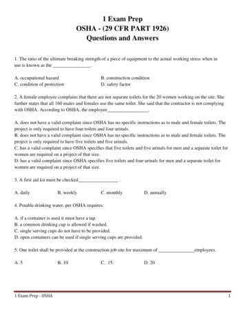
ROUGH-IN DIMENSIONS* NO SIDE OUTLET AVAILABLEFOR PCE 6 MODELSROUGH-IN DIMENSIONSModelsDimensionsPCE 6 1OMSAPCE 10 1OMSAPCE 17 OMSAPCE 20 1OMSAPCE 30 2OLSAPCE 40 2OLSAPCE 50 2OLSAPCE 30 2ORTAPCE 40 2ORTAPCE 52 2ORTAPCE 66 2ORTAPCE 82 2ORTAPCE 120 2ORTANo. ofElements1111222222222Tank CapacityUS Gals. 96625080303119450Ainches15 1/218 1/42622 1/430 7/832 1/432 1/434 1/245 1/854 7/860 3/459 3/862 Binches14 1/4181821 3/421 3/42426 1/220 1/220 1/220 1/221 3/42429 s1112 1/220 1/215 3/824 1/825 9/1625 1/8-mm279318521391613649638-Dinches ing 9RECOVERY CAPACITIESElementWattage(Upper/Lower)INPUTKWF C 36F 20C NON-SIMULATANEOUS LPH2136000/6000GPH686.0LPH256SIMULATANEOUS /6000GPH13512LPH51140F 22.2C U.S. Gallons/Hr and Litres/Hr at TEMPERATURE RISE INDICATED54F 60F 72F 80F 90F 100F 108F 120F 126F 30C 33.3C 40C 44.4C 50C 55.5C 60C 66.6C 70C 2697291103212239146Recovery capacities at 100 F rise equal: for non-simultaneous element operation 4.1 gal. x KW of one element; for simultaneous element operation 4.1 gal. x 2/3 KW of both elements. For other rises multiply element KW as previously explained by 410 and divide by temperature rise. Full load current for single phase total watts : voltage.2
FOREWORDreduce the risk of injury under these conditions, it is recommendedthat the hot water faucet be opened for several minutes at a nearbykitchen sink before using any electrical appliance connected to thehot water system. If hydrogen is present, there will probably be anunusual sound such as air escaping through the pipe as the waterbegins to flow. THERE SHOULD BE NO SMOKING OR OPENFLAME NEAR THE FAUCET AT THE TIME IT IS OPENED.Thank you for buying this energy efficient water heater fromState. We appreciate your confidence in our products. Detailedinstallation diagrams are in this manual. These diagrams willserve to provide the installer with a reference for the materialsand method of piping suggested. IT IS NECESSARY THAT ALLWATER PIPING AND THE ELECTRICAL WIRING BE INSTALLEDAND CONNECTED AS SHOWN IN THE DIAGRAMS.CAUTIONAN ELECTRICAL GROUND IS REQUIRED TO REDUCE RISKOF ELECTRIC SHOCK OR POSSIBLE ELECTROCUTION. THEGROUND SCREW AT THE JUNCTION BOX IS FOR BONDINGTHE HEATER TO A GROUNDED SERVICE ENTRANCECONDUCTOR, A GROUNDED SERVICE ENTRANCE RACEWAY,OR AN EARTH GROUNDING ELECTRODE CONDUCTOR.In addition to these instructions, the water heater must be installedin accordance with local codes and the authority havingjurisdiction.GENERAL SAFETY INSTRUCTIONSBE SURE TO TURN OFF POWER WHEN WORKING ON ORNEAR THE ELECTRICAL SYSTEM OF THE HEATER. NEVERTOUCH ELECTRICAL COMPONENTS WITH WET HANDS ORWHEN STANDING IN WATER. WHEN REPLACING FUSESALWAYS USE THE CORRECT SIZE FOR THE CIRCUIT.WARNINGFAILURE TO FOLLOW THESE INSTRUCTIONS CAN RESULTIN SERIOUS PERSONAL INJURY OR DEATH.The principal components of the heater are identified on page6. The model and rating plate on page 5 interprets certainmarkings into useful information. Both of these referencesshould be used to identify the heater, its components and optionalequipment.INSTALLATION OR SERVICE OF THIS WATER HEATERREQUIRES ABILITY EQUIVALENT TO THAT OF A LICENSEDTRADESMAN IN THE FIELD INVOLVED. PLUMBING ANDELECTRICAL WORK ARE REQUIRED.REQUIRED ABILITYGENERALWARNINGFOR CALIFORNIA INSTALLATION THIS WATER HEATER MUSTBE BRACED, ANCHORED, OR STRAPPED TO AVOID FALLINGOR MOVING DURING AN EARTHQUAKE. SEE INSTRUCTIONSFOR CORRECT INSTALLATION AND PROCEDURES.INSTRUCTIONS MAY BE OBTAINED FROM YOUR LOCALDEALER, WHOLESALER, PUBLIC UTILITIES ORCALIFORNIA’S OFFICE OF STATE ARCHITECT, 400 P STREET,SACRAMENTO, CALIFORNIA 95814.The installation must conform to these instructions, the local codeauthority having jurisdiction, and the requirements of the powercompany. In the absence of code requirements follow the currentedition of NFPA-70, The National Electrical Code which may beordered from: National Fire Protection Association,1 Batterymarch Park, Quincy, MA 02269.LOCATIONThe water heater should be located as close as possible to/orcentralized to the water piping system. The water heater shouldbe located in an area not subject to freezing temperatures.INSULATION BLANKETSInsulation blankets available to the general public for externaluse on electric water heaters are not approved for use on yourState water heater. The purpose of an insulation blanket is toreduce the standby heat loss encountered with storage tank waterheaters. Your State water heater meets or exceeds the NationalAppliance Energy Act standards with respect to insulation andstandby loss requirements, making an insulation blanketunnecessary.The heater should be located in an area where leakage of thetank or connections will not result in damage to the area adjacentto the heater or to lower floors of the structure.When such locations cannot be avoided, a suitable drain panshould be installed under the heater.Such pans should be at least two inches deep, have a minimumlength and width of at least two inches greater than the diameterof the heater and should be piped to an adequate drain.WARNINGShould you choose to apply an insulation blanket to this heater,you should follow these instructions (See page 5 for identificationof components mentioned below). Failure to follow theseinstructions can result in fire, serious personal injury or death.Drain pans suitable for these heaters are available from yourdistributor or State Water Heaters, 500 Tennessee Waltz Parkway,Ashland City, TN 37015. Do not cover the temperature & pressure relief valve. Do not cover the instruction manual. Keep it on the side ofthe water heater or nearby for future reference. Do obtain new labels from State Water Heaters for placementon the blanket directly over the existing labels.Water heater life depends upon water quality, water pressure andthe environment in which the water heater is installed. Waterheaters are sometimes installed in locations where leakage mayresult in property damage, even with the use of a drain pan pipedto a drain. However, unanticipated damage can be reduced orprevented by a leak detector or water shut-off device used inconjunction with a piped drain pan. These devices are availablefrom some plumbing supply wholesalers and retailers, and detectand react to leakage in various ways:EXTENDED NON-USE PERIODSCAUTIONHYDROGEN GAS CAN BE PRODUCED IN A HOT WATERSYSTEM SERVED BY THIS HEATER THAT HAS NOT BEEN USEDFOR A LONG PERIOD OF TIME (GENERALLY TWO WEEKS ORMORE). HYDROGEN GAS IS EXTREMELY FLAMMABLE. To Sensors mounted in the drain pan that trigger an alarm or turnoff the incoming water to the water heater when leakage isdetected.3
CALCULATINGAMPERAGE/OVERCURRENT PROTECTION Sensors mounted in the drain pan that turn off the water supplyto the entire home when water is detected in the drain pan. Water supply shut-off devices that activate based on the waterpressure differential between the cold water and how waterpipes connected to the water heater. Devices that will turn off the gas supply to a gas water heaterwhile at the same time shutting off its water supply.The heaters come from the factory in two configurations:1. Two wire C-2 circuit for single element heater equipped with ahigh limit control, single phase power input.2. Four wire A-8 circuit for dual element heater equipped withtwo high limit controls, single phase or three phase powerinput.CLEARANCESA minimum clearance of 4” must be allowed for access toreplaceable parts such as thermostats, drain valve and relief valve.The heater with dual elements is factory wired for connection toa three wire, three-phase delta branch circuit, non-simultaneousoperation. In addition a ground conductor is required.Adequate clearance for servicing this appliance should beconsidered before installation, such as changing the anodes, etc.Element connection is for non-simultaneous operation. Thismeans only one element at a time operates. The wiring diagram,on page 5, shows the heater may be field converted tosimultaneous element operation by moving the red wire on“J” terminal to L1. It is then possible for both elements to operateat once as determined by the thermostats. Regardless ofelement connection the heater operates in an “unbalanced”fashion.FLOOD WARNINGIF THE HEATER BECOMES IMMERSED IN WATER UP TO ORABOVE THE LEVEL OF THE BOTTOM OF THE ELEMENTDOORS, THE HEATER SHOULD BE EXAMINED BY ACOMPETENT SERVICE PERSON BEFORE IT IS PLACED INOPERATION.The heater may be field converted to single-phase operation bymoving the wire on L3 of the terminal block to L2. L3 is not used,see page 5.CHEMICAL VAPOR CORROSIONWater heater corrosion and component failure can be caused bythe heating and breakdown of airborne chemical vapors. Spraycan propellants, cleaning solvents, refrigerator and air conditioningrefrigerants, swimming pool chemicals, calcium and sodiumchloride, waxes, and process chemicals are typical compoundswhich are potentially corrosive. These materials are corrosive atvery low concentration levels with little or no odor to reveal theirpresence. Products of this sort should not be stored near theheater.The heater, now in single-phase non-simultaneous operation, maybe field-converted to single phase simultaneous operation bymoving the red wire on terminal “J” to L1, see page 5.This is an example of calculating heater amperage for both typesof element operation. From this, the branch circuit conductorand overcurrent protection sizing can be established.The example is of a three-phase 240 volt unit with two, 6 kwelements. The notations are for units field converted tosingle-phase. Check the heater model and rating plate for actualspecifications and substitute those values in the following.ELECTRICAL (GENERAL)Check the heater model and rating plate information against thecharacteristics of the branch circuit electrical supply. DO NOTCONNECT THE HEATER TO AN IMPROPER SOURCE OFELECTRICITY. Contact the heater supplier for conversioninformation if necessary.Voltage applied to the heater should not vary more than 5%to -10% of the model and rating plate marking for satisfactoryoperation.DO NOT ENERGIZE THE BRANCH CIRCUIT FOR ANY REASONBEFORE THE HEATER TANK IS FILLED WITH WATER. DOINGSO WILL CAUSE THE HEATING ELEMENTS TO BURN OUT.The factory wiring is attached to a terminal block within the externaljunction box unit. The branch circuit is connected to the terminalblock within this junction box. The water heater should beconnected to a separate, grounded, branch circuit with overcurrentprotection and disconnect switch. The water heater should begrounded in accordance with national and local codes.Non-simultaneous:(as factory wired)Simultaneous:(Field conversion)3000 : 240 12.5 amps*3000 : 240 12.5 amps*12.5 x 1.73 21.6 amps*NOTE: as a single-phasenon-simultaneous unit.*NOTE: as a single-phasesimultaneous unit thetotal is:12.5 x 2 25 ampsThe rating of the overcurrent protection should be computed onthe basis of 125 percent of the total connected load amperage.Where the standard ratings and settings do not correspond withthis computation, the next higher standard rating or setting shouldbe selected.Portion of Table 310-16 (NFPA-70) follows:Allowable Ampacities of Insulated Copper Conductors. Not morethan three conductors in Raceway or Cable or Direct Burial (Basedon Ambient Temperature of 30 C, 86 F).BRANCH CIRCUITThe branch circuit wire size should be established throughreference to the current edition of NFPA-70, theNational Electrical Code or other locally approved source inconjunction with the heater amperage rating. For convenience,portions of the wire size tables from the Code are reproducedhere. The branch circuit should be sized at 125 percent of theheater rating and further increase wire size as necessary tocompensate for voltage drop in long runs.These ampacities relate only to conductors described in Table310-13 in Code.For ambient temperatures over 30 C (86 F), see CorrectionFactors, Note 13 in Code.4
SizeAMGMCM18161412108643SizeTemperature Rating of ConductorSee Table 310-13 in Code60 C75 C(140 F)(167 F)TYPES:TYPES:RUWRH, RHW, RUH,(14-2),(14-2), THWT, TW,THWN, MCM1210864321Temperature Rating of ConductorSee Table 310-13 in Code60 C75 C(140 F)(167 F)TYPES:TYPES:RUWRH, RHW, RUH,(12-2),(12-2), THWT, TW,THWN, XHHW,UFUSE151525253040405055656575759085100Portion of Table 310-18 follows:Allowable Ampacities of Insulated Aluminum and Copper -Clad Aluminum Conductors.Not more than three conductors in Raceway or Cable or Direct Burial (Based on Ambient Temperature of 30 C, 86 F. Theseampacities relate only to conductors described in Table 310-13 in Code.For ambient temperatures over 30 C (86 F), see Correction Factors, Note 13 in Code.WIRING DIAGRAMSA-8 CIRCUIT FOR DUAL ELEMENT HEATERC-2 CIRCUITFOR SINGLEELEMENT HEATERSEQUIPPED WITH HIGHLIMIT CONTROLFACTORY WIRED---------- FIELD WIRING† WHITE FOR 120VAND 277V5
TYPICAL PIPING CONNECTIONSThis page shows typical water heater installations by model designations.DUAL ELEMENTS HEATERSINGLE ELEMENT HEATERINSTALL SUITABLE DRAIN PANS UNDER HEATERS TOPREVENT DAMAGE DUE TO LEAKAGE. REFER TO WATERHEATER LOCATION ON PAGE 2.INSTALL THERMALEXPANSION TANK IFCHECK VALVE ORPRESSURE REDUCINGVALVE IS USED INSUPPLY LINE.INSTALL VACUUM RELIEFIN COLD WATER INLETLINE AS REQUIRED BYLOCAL CODES.† OVER CURRENT PROTECTION MUST BE SUPPLIED IN WATER HEATER CIRCUIT.CONSULT LOCAL CODE OR NFPA 70 FOR PROPER INSTALLATION.* INSTALL IN ACCORDANCE WITH ALL LOCAL CODES.TEMPERATURE AND PRESSURE RELIEF VALVEthat any discharge from the valve will exit only within 6 inchesabove, or at any distance below, the structural floor and cannotcontact any live electrical part. THE DISCHARGE OPENINGMUST NOT BE BLOCKED OR REDUCED IN SIZE UNDER ANYCIRCUMSTANCES.CAUTIONTO REDUCE THE RISK OF EXCESSIVE PRESSURES ANDTEMPERATURES IN THIS WATER HEATER, INSTALLTEMPERATURE AND PRESSURE PROTECTIVE EQUIPMENTREQUIRED BY LOCAL CODES BUT NOT LESS THAN ACOMBINATION TEMPERATURE AND PRESSURE RELIEFVALVE CERTIFIED BY A NATIONALLY RECOGNIZED TESTINGLABORATORY THAT MAINTAINS PERIODIC INSPECTION OFPRODUCTION OF LISTED EQUIPMENT OR MATERIALS, ASMEETING THE REQUIREMENTS FOR RELIEF VALVE DEVICESFOR HOT WATER SUPPLY SYSTEMS. (ANSI Z21.22.)DUAL ELEMENTRATING PLATEThis valve must be marked with a maximum set pressure not toexceed the marked maximum working pressure of the waterheater. Install the valve into an opening provided and marked forthis purpose in the water heater, and orient it or provide tubing so6SINGLE ELEMENTRATING PLATE
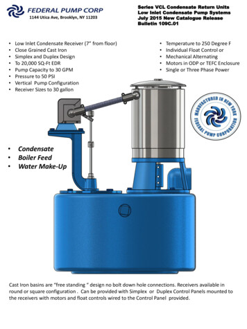
Figure 3 shows the approximate time-to-burn relationship fornormal adult skin. The thermostats on your water heater have alinear relationship between degrees of angular rotation and thecorresponding change in temperature. Thus rotating thetemperature adjustment indicator 30 angular degrees will resultin a 10 degree Fahrenheit change in water temperature.OPERATIONCAUTIONDO NOT OPERATE THE HEATER WITHOUT INSTALLING ANAPPROVED TEMPERATURE AND PRESSURE RELIEF VALVEIN THE OPENING PROVIDED IN THE TANK. GROUND THEHEATER TO GUARD AGAINST ELECTRIC SHOCK FROM THEHEATER OR WATER SYSTEM. NEVER OPERATE THE HEATERWITHOUT FILLING WITH WATER PER THE FILLINGINSTRUCTIONS. FAILURE TO DO SO WILL DAMAGEINTERNAL PARTS.FILLING1. Close the water heater drain valve by turning hand-wheel toright (clockwise).TemperatureTime to Produce 2nd & 3rdSettingDegree Burns on Adult Skin180 F (82 C)160 F (71 C)150 F (66 C)140 F (60 C)130 F (54 C)125 F ( 52 C)120 F (49 C)Nearly instantaneousAbout 1/2 secondAbout 1-1/2 secondsLess than 5 secondsAbout 30 secondsAbout 2 minutesMore than 5 minutes2. Open a nearby hot water faucet to permit the air in the systemto escape.FIGURE 3.TEMPERATURE ADJUSTMENT3. Fully open the cold water inlet valve allowing the heater andpiping to be filled.The water temperature is controlled by surface mountedthermostats with hi-limit. There is one mounted firmly against thetank directly above each element. The thermostats of A-8 circuitare adjustable from approximately 120 F (49 C) (lowest setting)to 180 F (82 C) (highest setting). The thermostat of C-2 circuit isadjustable from approximately 110 F (43 C) to 170 F (77 C) witha factory set point 120 F (49 C). The over temperature device(hi-limit) attached to each thermostat has a manual reset.4. Close the hot water faucet as water starts to flow.5. Turn on the electrical switch to the water heater.WARNINGDO NOT ATTEMPT TO OPERATE HEATER WITH COLD WATERINLET VALVE CLOSED.TEMPERATURE REGULATIONDANGERTHE WATER HEATER IS EQUIPPED WITH AN ADJUSTABLETHERMOSTAT TO CONTROL WATER TEMPERATURE. HOTWATER AT TEMPERATURES DESIRED FOR AUTOMATICDISHWASHER AND LAUNDRY USE CAN CAUSE SCALDSRESULTING IN SERIOUS PERSONAL INJURY AND/OR DEATH.THE TEMPERATURE AT WHICH INJURY OCCURS VARIESWITH THE PERSON’S AGE AND TIME OF EXPOSURE. THESLOWER RESPONSE TIME OF CHILDREN , AGED ORDISABLED PERSONS INCREASES THE HAZARD TO THEM.NEVER ALLOW SMALL CHILDREN TO USE A HOT WATER TAP,OR TO DRAW THEIR OWN BATH WATER. NEVER LEAVE ACHILD OR DISABLED PERSON UNATTENDED IN A BATHTUBOR SHOWER.ADJUSTABLE UPPERTHERMOSTAT BEHINDJUNCTION BOX DOORADJUSTABLELOWER (SINGLE)THERMOSTATFIGURE 4.NOTE: It is not necessary to adjust the upper thermostat for adual element unit. However, if it is adjusted above the factory setpoint 140 F (60 C) it is recommended that it not be set higherthan the lower thermostat setting.To change the temperature setting:DANGER1. Turn off the heater electrical supply. Do not attempt to adjustthermostat with power on.It is recommended that lower water temperatures be used toavoid the risk of scalding. It is further recommended, in all cases,that the water heater thermostats be set for the lowesttemperature which satisfies your hot water needs, see Figure 3.This will also provide the most energy efficient operation of thewater heater.2. Open the junction box door (for upper thermostat of dualelement water heater only) and/or remove the (lower)thermostat access panel. Do not remove the plastic personnelprotectors covering the thermostats. The thermostat is factorypre-set at 140 F (60 C) for dual element units or at 120 F(49 C) for single element units.7
3. Using a flat tip screwdriver, rotate the adjusting knob to thedesired temperature setting.Once a month the temperature and pressure relief valve shouldbe checked to ensure that it is in operating condition. Lift thelever on the valve several times until the valve seats properly andoperates freely.4. Replace the covers and access panels, and turn on heaterelectrical supply.CAUTIONTHE WATER PASSING OUT OF THE VALVE DURING THISCHECKING OPERATION MAY BE EXTREMELY HOT.Valves for reducing point-of-use temperature by mixing cold andhot water are available, see Figure 5 . Also available areinexpensive devices that attach to faucets to limit hot watertemperatures. Contact a licensed plumber or the local plumbingauthority.It is recommended that the drain valve on this unit be openedonce a month and 1 to 2 gallons of water be allowed to drainout. This will help to prevent sediment buildup in the tankbottom.A non-adjustable high temperature limit control operates beforesteam temperatures are reached. The high limit is in the samearea as the upper thermostat and must be reset manually when itoperates. BECAUSE THE HIGH LIMIT OPERATES ONLY WHENABNORMALLY HIGH WATER TEMPERATURES ARE PRESENT,IT IS IMPORTANT THAT A QUALIFIED SERVICE AGENT BECONTACTED TO DETERMINE THE REASON FOR OPERATIONBEFORE RESETTING.ANODE INSPECTION AND REPLACEMENTThis water heater is equipped with a sacrificial anode. Anodesprotect the glass-lined tank from corrosion by sacrificingthemselves through electrolysis. When the anode material isconsumed, there is no more protection and corrosion of the tankaccelerates.Inspection of the anode every 6 to 12 months allows you toidentify a spent anode and replace it. Replace the anodewhen its diameter is 3/8" (1 cm) of an inch, or annuallywhich ever is first. Aggressive, very hot and softened watercauses rapid consumption of the anode requiring frequentinspections. Anodes are available from your distributor orA.O. Smith.FIGURE 5.TROUBLESHOOTINGDRAININGCHECKLISTIf the heater is to be shut down and exposed to freezingtemperatures, it must be drained. Water, if left in the tank andallowed to freeze, will expand and damage the heater.Before contacting your dealer, check the water heater to see ifthe apparent malfunction is caused by some external fault.Consulting this checklist may eliminate the need for a repair calland restore hot water service.1. Turn off the electrical switch and cold water inlet valve.NOT ENOUGH OR NO HOT WATER If desired, a hose may be connected to the drain valveto carry the water away.1. Be certain that the water heater electrical switch is turned tothe ON position.2. Open a nearby hot water faucet and the heater drainvalve. In some areas an additional special meter, controlledby a timer, is used to govern the periods electricity isavailable. If the heater operates on a timed electricalcircuit, recovery will be limited to certain hours. Be careful to grasp the drain valve handle in such away that the hand will not be exposed to hot water.3. The drain valve must be left open during the shutdownperiod.2. Check for loose or blown fuses in the water heater circuit. To restart heater, refer to the foregoing FILLINGinstructions.3. If the water has been excessively hot and is now cold, the hightemperature limit control may have operated. To restoreservice, contact your dealer or utility company. Refer toTEMPERATURE REGULATION section.MAINTENANCEElectric water heater maintenance consists of cleaning the tankand removing lime (or scale) from the heating elements in hardwater areas. Tank flushing should be performed monthly. Tanksediment removal and element lime scale removal must beperformed when needed as determined by periodic inspections.Your dealer should be contacted for element cleaning. In someinstances a hissing sound may be heard as the scale builds up.This noise is normal.4. The storage capacity of the heater may have been exceededby large demands of hot water.5. If the heater was installed when incoming water temperatureswere warm, colder incoming temperatures will create the effectof less hot water.6. Look for leaking or open hot water faucets.8
WATER IS TOO HOTExcessive water pressure is the most common cause of reliefvalve leakage. It is often caused by a “closed system”. A checkvalve in the inlet system will not permit the expanded hot watervolume to equalize pressure with the main. A relief valve mustrelease this water or the water heater or plumbing system will bedamaged.1. Refer to TEMPERATURE REGULATION section.WATER HEATER MAKES SOUNDS1. See MAINTENANCEDamage to the water heater caused by a closed system is notcovered by the limited warranty. The only solution is to install athermal expansion tank between the check valve and the coldwater inlet to the heater.WATER LEAKAGE IS SUSPECTED1. Check to see if the heater drain valve is tightly closed.2. The apparent leakage may be condensation which forms oncool surfaces of the heater and piping.IF YOU CANNOT IDENTIFY OR CORRECTTHE SOURCE OF THE MALFUNCTION3. If the outlet of the relief valve is leaking it may represent:1. Place the water heater electrical switch in the OFF position. Excessive water pressure.2. Close the cold water inlet valve to the heater. Excessive water temperature. Faulty relief valve.3. Contact your dealer.NOTES9
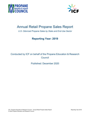
LEAKAGE CHECKPOINTSInstructions: Use this illustration as a guide when checking for sources of water leakage. You or your dealer may be able to correct whatappears to be a problem. NOTE: Cover and Insulation shown removed to reveal tank topWhere possible remove or lift top cover toexamine threads of fittings installed intotank for evidence of leakage. Correct fittingleaks as necessary.Relief ValveCondensation and dripping may appearon pipes when cold water temperatureis low. Pipe fitting may be leaking.Water leaks at the elementsmay be due to:1. Defective element which leaks atterminals or thru flange. Replaceelement*.To Open DrainAnode Rod (Some Models)Relief valve operation and leakage maybe due to water expansion duringheating cycle or foreign material on seatof valve. If the valve is not piped to anopen drain the released water could bemistaken for a leaking heater. Check forleakage where the threaded portion ofthe relief valve enters the tank. Removevalve* if indicated and repair with pipejoint compound.2. Loose element/gasket leak:(a) Screw-in type: tighten with1-1/2” socket wrench or Part Number23985 wrench. If leak continues,remove element*, discard gasketand clean thread areas. ApplynonhardeningPermatex Number 2 tothread areas, install new gasket andscrew element into fitting until it seats.Tighten 1/2 to 3/4 turn with wrench.(b) Flange type: tighten screw withwrench. If leak continues removeelement* and discard gasket. Cleangasket seating areas and re-installelement with new gasket. NOTE: PartNumber 40000-1 scale cleaningreplacement screws available wherethreads have become rusted ordamaged, preventing tightening.To Open DrainWater on the side of the tank may becondensation due to the panel orinsulation not being in place.Drain valve leakage could be from thevalve itself.* To check for leakage wherethreaded portion enters tank, insert Qtip or similar absorbent materialbetween jacket opening and valve toswab spud area. Remove valve* if leakis indicated and repair with pipe jointcompound.All water which appears at the heaterbottom or on the surrounding floor maybe caused by condensation, looseconnections or relief valve operation andleakage. Do not replace the heater untilfull inspection of all potential leak pointsis made and corrective steps taken to stopthe leak. Leakage from other appliances,water lines or ground seepage should alsobe suspected until proven otherwise.*Contact your dealer as it is necessary toshut off electricity and drain tank to performprocedure.10
REPAIR PARTS LISTNow that you have purchased this water heater, should a needever exist for repair parts or service, simply contact the companyit was purchased from or direct from the manufacturer listed onthe rating plate on the water heater.Be sure to provide all pertinent facts when you call or visit.WHEN ORDERING REPAIR PARTS, ALWAYS GIVE THEFOLLOWING INFORMATION: Selling prices will be furnished on request or parts will beshipped at prevailing prices and you will be billed accordingly.The model number of your Water Heater will be found on therating plated located above the lower access panel.MODEL NUMBERVOLTAGE AND ELEMENT WATTAGESERIAL NUMBERPART DESCRIPTIONPCE 6 thru PCE 20 - refer to Repair Parts Table on page 12 forSingle Element Electric Units.DRAIN VALVE(not supplied with heater)Part No. 900390611
ItemDescriptionPCE-610MSASeries 102PCE-1010MSASeries 102PCE-1710MSASeries 102PCE-2010MSASeries 1021A . Anode, Alum. . 9003942 . 9003942 . 9003943 . 90039441B . Anode, Mag. . 9002110 . 9002110 . 9004302 . 90037212 . Collar, Pipe . 9004610 . 9004610 . 9004610 . 90046103 . Cover, Front . 9003900 . 9003900 . 9003900 . 90039004 . ELEMENT, HEATING . SEE ELEMENT CHART ON PAGE 14 .5 . Gasket, Element . 9000308 . 9000308 . 9000308 . 90003086 . Opening Insulation . 43307 . 43307 . 43307 . 433077 . *Instruction Manual . 195202-002 . 195202-002 .195202-002 . 195202-002LABEL8 . *Scald Warning . 181138 . 181138 . 181138. 1811389 . *Temperature Warning . 182734 . 182734 .
of the heater and should be piped to an adequate drain. Drain pans suitable for these heaters are available from your distributor or State Water Heaters, 500 Tennessee Waltz Parkway, Ashland City, TN 37015. Water heater life depends upon water quality, water pressure and the environment in which the water heater is installed. Water