Transcription
White PaperNorthStar Controller—MultilayerSDN Coordination and OptimizationController-to-controller interface exchanges abstract topology information, providing a straightforwardand highly scalable approach for coordination between both network layers1
NorthStar Controller—Multilayer SDN Coordination and OptimizationWhite PaperTable of ContentsExecutive Summary . 3Introduction. 3Active Stateful PCE Architecture. 4The NorthStar Controller. 4Separation of Protocol Layers. 5Network Topology Abstraction . 6Abstract Topology Exchange.7Multilayer Coordination Use Cases . 8Multilayer Topology Visualization . 8Multilayer Path Diversity. 9Visibility to Transport-Layer Restoration. 10Visibility to Transport-Layer Protection In Use. 10Multilayer Maintenance Coordination.11Conclusion.12References.13About Juniper Networks.13List of FiguresFigure 1: Interfaces between the IP/MPLS network and the NorthStar Controller. 4Figure 2: Transport and IP/MPLS network layers strongly differ in management and control interfaces. 5Figure 3: Abstraction of the transport-layer topology: point-to-point link (left), and meshed network (right). 6Figure 4: Actual transport and IP/MPLS network topology (left); view from the IP/MPLS layer without abstracttopology exchange (middle); and view from the IP/MPLS layer with abstract topology exchange (right). 6Figure 5: C ontroller-to-controller abstract topology exchange between the NorthStar Controller anda transport SDN controller.7Figure 6: Initial topology synchronization (left) and incremental topology updates (right). 8Figure 7: Example GUI of a multilayer network topology in the NorthStar Controller. 9Figure 8: SRLG information exchange during transport-layer restoration (2). Both the transport andIP/MPLS network exchange topology changes (3). 10Figure 9: Exchange of protection information between transport layer and IP/MPLS network topology.11Figure 10: C oordinated maintenance between transport and IP/MPLS layers through the exchange of abstractlink with time stamps (1) and actual network topology changes (3).12 2015, Juniper Networks, Inc.2
NorthStar Controller—Multilayer SDN Coordination and OptimizationWhite PaperExecutive SummaryMultilayer coordination between the transport and IP/MPLS layers of a network is one of the most promising approachesto building a more optimized and simpler multilayer network architecture. However, this also presents a significanttechnical challenge, as it involves coordination between very different technologies on each of the network layers, eachwith its own approach and legacy for network control and management.Transport networks have traditionally relied on the use of centralized network management through a networkmanagement system (NMS), whereas the IP/MPLS layer uses a distributed control plane in order to build highly robustand dynamic network topologies. These fundamentally different approaches towards network control have proven to bea significant challenge over the years when the industry has tried to realize a closer integration between both networklayers. A considerable body of research and development has been spent in the industry on multilayer coordination overthe preceding two decades, but as of today only a few successful examples of multilayer coordination exist, and thentypically only in a single vendor environment.The recent development of centralized SDN controllers for the IP/MPLS layer enables new opportunities for packetoptical coordination between the transport and IP/MPLS layer. This architecture relies on a controller-to-controllerinterface to exchange abstract topology information, thereby providing a straightforward and highly scalable approachfor coordination between both network layers [1]. This whitepaper illustrates the architecture of the controller-tocontroller interface that allows for the exchange of topology information between the transport and IP/MPLS layers. Italso details some of the use cases that this exchange of information will enable.IntroductionThe first question to consider is whether to use centralized versus distributed multilayer coordination. In the past,multilayer coordination focused mostly on Generalized MPLS (GMPLS) [1] control planes in the transport and IP/MPLSnetwork layers. GMPLS also provides a distributed control plane for the transport layer, which opens up the possibilityof control plane integration between both network layers. Within the transport layer, GMPLS control planes have beensuccessfully deployed for several years, and multilayer control through GMPLS-UNI [1]/GMPLS-ENNI [2] architectureshave more recently been available as well. However, control plane integration between different vendors and technologydomains is notoriously difficult and generally requires a lot of software development and integration testing due tothe fact that the two control planes need to be tightly integrated with each other. This is particularly difficult sincemost transport platforms have highly centralized management architectures, whereas the IP/MPLS layer is inherentlybased on a dynamic control plane. Hence, every combination of transport and IP/MPLS across system vendors requiresextensive dedicated testing (and retesting after software upgrades). This doesn’t scale very well, and although GMPLS isa technically sound approach, it is nearly impossible to productize it in a multivendor environment.Recently there has been a focus on a more centralized control of the IP/MPLS layer. This is one of the key characteristicsof SDN, as centralized control generally makes it easier to program or influence routing decisions through a northboundinterface for integration into management, provisioning, and orchestration platforms. A centralized controller for thecoordination and optimization of the IP/MPLS layer enables a global view of the network topology and provides benefitsthrough the use of highly optimized traffic engineering algorithms that make use of that global network visibility. Acentralized IP/MPLS network controller also provides the possibility of multilayer control through an interface betweenthe transport layer and IP/MPLS layer SDN controllers.A multilayer controller-to-controller interface maintains the demarcation between the transport and IP/MPLS layers,while at the same time addressing the challenges associated with multilayer coordination and optimization. Acontroller-to-controller interface between a transport and IP/MPLS network controller is therefore a much simplerapproach compared to GMPLS integration between network layers, predominantly as it does not involve thesynchronization of state across multiple distributed control planes. There is no protocol interoperability needed betweenthe transport and IP/MPLS layers, and no requirement for coordinated software upgrades. The technologies used in eachof the network layers can therefore continue to evolve in a multivendor, multi-technology environment, each with its ownapproach for network control and management.In short, multilayer control through a controller-to-controller interface addresses most of the same goals and usecases of control plane integration based on GMPLS and can therefore be a suitable alternative, specifically formultivendor deployments. 2015, Juniper Networks, Inc.3
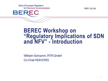
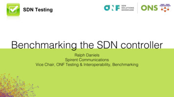
NorthStar Controller—Multilayer SDN Coordination and OptimizationWhite PaperActive Stateful PCE ArchitectureJuniper’s SDN architecture for centralized WAN control and optimization in based on a Path Computation Element(PCE) architecture. The PCE is an entity (component, application, or network node) that is capable of computing anetwork path or route based on a network graph and applying computational constraints [3]. A Path ComputationClient (PCC) is any client application requesting that a path computation be performed by a PCE. In a centralized PCEarchitecture, the network elements act as PCC, where the PCC interface is integrated into the router operating system.The Path Computation Element Protocol (PCEP, RFC5440) enables communications between a PCC and a PCE [4].It is a TCP-based protocol defined by the IETF PCE Working Group, and defines a set of messages and objects used tomanage PCEP sessions. The PCE sends path setup requests to the PCC via PCEP, and the PCC sends report messagesto the PCE for it to learn the label-switched path (LSP) state in the network.Traditionally, PCE architectures have been passive and stateless, i.e., the PCE only computes the path on request ofthe PCC and is not aware of the LSP state already in the network. More recently, active stateful PCE architectures havebecome popular [5]. An active stateful PCE obtains the LSP and bandwidth reservations in the network by synchronizingthe LSP state between the PCE and the PCC running on the network elements using PCEP. It can, therefore, activelyinstall and modify paths in the network based on user input through the GUI or based on input received through theRESTful northbound interface.The actual path setup in the network happens through RSVP-TE, as shown in Figure 1, which is a widely used protocolsuite for traffic engineering in IP/MPLS networks that has been extensively deployed for many years in WAN deploymentsworldwide. This allows the upgrade of Brownfield network deployments by a simple software upgrade of the networknode acting as PCC, and it enables a gradual transition of network services from distributed control to an SDN-enabledcentralized control.Active Stateful PCEArchitectureRSVP SignalingPCCPCCPCCPCC Topology discovery(BGP-LS, IGP-TE) Report LSP state (PCEP) Create LSP state (PCEP)MPLS NetworkNorthStar Controller(PCE)Figure 1: Interfaces between the IP/MPLS network and the NorthStar ControllerThe NorthStar ControllerJuniper Networks NorthStar Controller is an active stateful PCE and utilizes PCEP to obtain LSP state in the network forcentralized control and optimization of network resources [6, 7]. Juniper Networks Junos operating system integratesthe PCC, allowing the NorthStar Controller to obtain the LSP state from any Juniper platform running a suitable JunosOS release, as well as any third-party routers supporting RFC5440. The NorthStar Controller itself is a softwareapplication running on any suitable third-party x86 hardware platform. NorthStar Controller peers with the networkin order to obtain a global view of the network topology, typically using BGP-LS by importing the traffic engineeringdatabase (TED) [8]. Alternatively, it can also learn the network topology through the use of OSPF/ISIS-TE.The combined visibility of the network topology and complete LSP state in the network allows the NorthStar Controllerto provide more optimized traffic engineering (TE) compared to a distributed control plane where each network elementhas a complete view of the topology (within a domain/area) but only knows the local LSP state. NorthStar Controller,therefore, enables a diverse range of use cases such as diverse path computation, premium path computation,maintenance mode rerouting, bandwidth scheduling/calendaring, and bin packing or network defragmentation. Theinterface between NorthStar Controller and one or more transport layer SDN controllers further extends NorthStarController’s visibility into the transport layer and allows it to address the multilayer coordination and optimization usecases described here. 2015, Juniper Networks, Inc.4
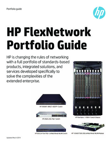
NorthStar Controller—Multilayer SDN Coordination and OptimizationWhite PaperSeparation of Protocol LayersCommunication networks generally rely on a concept of separate protocol layers. The most common model to describethe separation of network layers is the OSI model, but in practice many different protocol stacks are deployed intoday’s networks. The concept of separate network layers was originally invented for scalability and interoperabilityconsiderations, and the ability to use standardized protocols. Over time, the split of communication networks intodifferent layers has also influenced organization, security, and technology considerations. Different equipment is usedto implement the different network layers, often built by different system vendors and operated by different parts of theoperator’s organization.IP/MPLS Layer(’Client-layer’)Transport Layer(’Server-layer’)Figure 2: Transport and IP/MPLS network layers strongly differ in management and control interfacesTransport and IP/MPLS are examples of different network layers that effectively use a client/server approach, where theIP/MPLS layer is a client of the transport server layer as illustrated in Figure 2. The client layer, in this configuration, hasno or only very limited knowledge of the server layer, i.e., the IP/MPLS layer is “blind” to the actual topology and resourceavailability on the transport layer. Unfortunately, this loss of information also complicates network design and operations,and in particular the disconnected network layers are a burden for multilayer optimization (MLO) of network resources.The lack of transport layer topology and resource availability information on the IP/MPLS layer results in morecomplicated service provisioning and disconnected planning processes. It is often desirable that the client layer influencethe routing of the services it provides across the server layer. For example, services sometimes need to use paths thatare as disjointed from each other as possible. If an interface or link in the network fails, the distributed IP/MPLS controlplane can automatically restore traffic to an alternative path using MPLS fast reroute (FRR) or similar restorationmechanisms. However, for this restoration to be successful, it is critical that both active and standby paths do not sharethe same resources on the transport layer, i.e., Shared Risk Link Group (SRLG) information, which would result in asimultaneous failure of the active and standby path and therefore a complete loss of connectivity. Traditionally, the IP/MPLS layer has no direct visibly into SRLG information, as it only knows if a circuit is “up” or “down” and does not knowwhich circuits are fate sharing. It can learn SRLG information by including the information in the IGP [9]. However, thisrequires manual configuration of the SRLG information based on data obtained from the transport and/or fiber topology,which is a labor-intensive and error prone process. In addition, for transport networks that use a reconfigurable opticaladd-drop multiplexer (ROADM) to periodically optimize wavelength planning, the SRLG information is not static and thisnecessitates an automated update mechanism of the SRLG information in the IGP.Different services provided by the IP/MPLS layer can also have very different routing requirements. For example, someservices need to be optimized based on lowest cost criteria, while other services have the best delay characteristics.In particular, the exchange of delay information enables more service-aware TE that allows the IP/MPLS layer todifferentiate traffic engineering between lowest cost and premium lowest latency paths. As a result of the limitedinformation exchange between both layers, it is typically a highly manual process involving offline planning and oftenrelying on disconnected data sets to identify what services follow the most desired path across the transport layer. Thisrequires an exchange of metrics between both network layers, ideally an automated one. 2015, Juniper Networks, Inc.5
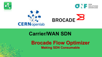
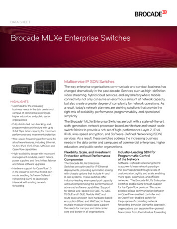
NorthStar Controller—Multilayer SDN Coordination and OptimizationWhite PaperClient-linkAccesslinkAbstract linkClient-linkAccesslinkAccesslinkAccesslinksrig: 2srig: 1AbstractnodeClient Layermetric:10,color: greensrig: 1AbstractnodeServer LayerAbstractnodeClient Layersrig: 3Abstract linkServer LayerAbstractnodeClient LayerFigure 3: Abstraction of the transport-layer topology: point-to-point link (left), and meshed network (right)Network Topology AbstractionDespite the previously mentioned drawbacks, it is generally still desirable to limit the information exchange between thetransport and IP/MPLS layers to the information that is directly useful to improve TE. This allows for higher scalability inlarge networks, but also addresses any organizational or security concerns that might exist when detailed configurationinformation is shared between both network layers.This can be achieved by summarizing the detailed design of the transport layer topology to the minimum set ofinformation required to address relevant multilayer TE use cases. The IP/MPLS layer only requires network topology anda limited set of metrics from the transport layer, and any more detailed information does not influence or improve trafficengineering accuracy. Detailed information on network element connectivity and optical transmission impairmentsof the transport layer can therefore be omitted from the information that is shared between the transport and IP/MPLS network layers. Instead, the transport layer (server layer) shares an abstracted topology model with the IP/MPLSlayer (client layer). This abstracted topology model consists of a set of abstract links that represent the end-to-endreachability on the server layer, as well as the metrics of these links such as bandwidth, latency, SRLGs, and so on.Figure 3 shows the abstraction of the transport layer into a set of abstract nodes and links. A link that connects atransport-layer node and a node in the IP/MPLS layer is referred to as an access link. Every node on the transport layerthat has one or more access links to the IP/MPLS layer is defined as an abstract node. Any transport node that does nothave any access link(s) is omitted from the abstracted topology, as it is not required to define the topology mappingbetween both network layers.SRLG-2?SRLG-1Abstract links are either actual or potential end-to-end links within the server layer that connect two abstract nodestogether. An abstract link can be a direct point-to-point connection between two abstract nodes, but it can alsorepresent the connectivity through a complex meshed network topology with multiple inline (ROADM) networkelements. Multiple abstract links can share the same server-layer links, in which case they are part of the same SRLG.Any link or node in the server layer that is shared by multiple abstract links can be the basis for a separate SRLG, and anabstract link will typically be associated with a string of SRLGs.Figure 4: Actual transport and IP/MPLS network topology (left); view from the IP/MPLS layer without abstract topologyexchange (middle); and view from the IP/MPLS layer with abstract topology exchange (right) 2015, Juniper Networks, Inc.6
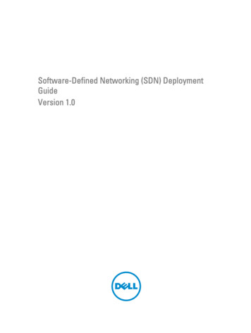
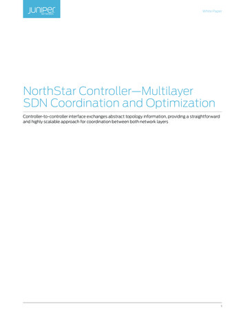
NorthStar Controller—Multilayer SDN Coordination and OptimizationWhite PaperThe reachability information in the abstract topology model covers both actually existing transport layer connectivity, aswell as potential connectivity. An actual abstract link is a link that can be used by the client layer to realize connectivity;for a transport network, this will normally imply that one or more wavelengths are installed between the near-end andfar-end transport nodes. Potential abstract links are all transport-layer circuits that can be supported given the serverlayer topology within the restrictions imposed by ROADM connectivity, or optical reach restrictions, but where no circuitsare installed. Each of the abstract links is described with a set of common “attributes” such as the bandwidth, cost,latency metrics, link coloring, and SRLGs. As a result, this abstracted topology concept considers all physical restrictionsof the transport layer, while hiding the complexity of the optical transmission impairments and ROADM connectivityfrom the IP/MPLS layer.Figure 4 gives an example of a transport and IP/MPLS network topology and the visibility on the IP/MPLS layer withand without exchange of the abstract server-layer topology. The set of abstract links defines the full set of actual andpotential connections through the meshed network. Using this abstract server-layer topology, the IP/MPLS layer can nowdetermine which server-layer connections are not part of the same SRLG and therefore are not fate sharing. In this way,it can guarantee diversity of a pair of LSPs without any manual SRLG configuration.Abstract Topology ExchangeThe information exchange between the transport and IP/MPLS layers is illustrated in Figure 5. The NorthStar Controllerobtains the topology information of the IP/MPLS layer by peering with the routers through, for example, BGP-LS, and itobtains the LSP state through the PCEP. The transport SDN controller will learn the transport network topology throughsouthbound interfaces such as SNMP, OpenFlow, or NETCONF. The protocols used by each of the SDN controllersfor control and configuration of the network, therefore, do not need to be identical, which is greatly beneficial in amultivendor multi-technology environment.The topology exchange between the transport SDN controller and the NorthStar Controller is implemented bydescribing the abstract topology in a YANG model. YANG (“Yet Another Networking Grammar”) is a data modelinglanguage described in RFC6020 [10]. It is used to model configuration and state data manipulated by the NetworkConfiguration Protocol (NETCONF, RFC6241) [11], NETCONF remote procedure calls, and NETCONF notifications. YANGgenerates XML-based configurations with a C-like syntax and a hierarchical structure. This makes it easy for operators tounderstand and engineers to implement YANG data models. The YANG data model describing the transport network inthe form of an abstracted network topology is detailed in IETF draft-ietf-teas-yang-te-topo-01 [12].QRSRLGVQWRTransport ControllerVSRLGWTransport ControllerYang Abstract Network TopologyPCEP, BGP-LS(Southboundinterface to NE)(RESTCONF via Northbound RESTful interface)SNMP, OpenFlow,NetConf, etc.(Southboundinterface to NE)Used Abstr. linkAbstr. linkPacket LSPOptical pathFigure 5: Controller-to-controller abstract topology exchange between the NorthStar Controller anda transport SDN controller 2015, Juniper Networks, Inc.7
NorthStar Controller—Multilayer SDN Coordination and OptimizationWhite PaperThe abstract network topology is exchanged between the transport SDN controller and the NorthStar Controller viaeither a RESTCONF [13] or REST [14] interface. Representational State Transfer (REST) is an architecture style forinformation exchange mainly used for the design of networking applications, where APIs that adhere to the RESTarchitectural constraints are called RESTful APIs. RESTful applications typically use HTTP requests to post data (create,or update, or both), read data (e.g., make queries), and delete data. A key property of a RESTful interface is that it isstateless, i.e., each request from any client contains all the information that is necessary to service the request. Thesession state is held only in the client. This is different from more traditional network management protocols such asSNMP that use a sequence of request and response calls between client and server and where state is held in both theserver and client.RESTCONF provides a lightweight alternative with a limited subset of the transaction capabilities of the NETCONFprotocol. It is a REST-like management protocol running over HTTP that describes how to map a YANG specification toa RESTful interface. It defines a simplified transaction model that allows for the basic create, update, read, and deleteoperations on a hierarchy of conceptual rthStarControllerTransportControllerInitiate TCP ConnectionInitiate 2nd TCP ConnectionACKACKAsk for Full Topo(GET/restconf/.Send Full TopoSubscribe tonotifications(GET/restconf/stream/Reply(200 OK. . . data)Heartbeat(200 OK. . . data)HeartbeatSend incremental.update(data: . . .).Send incremental update(data: . . .)Figure 6: Initial topology synchronization (left) and incremental topology updates (right)NorthStar Controller obtains the abstract network topology from the transport-layer controller by sending a GET requestas shown in the example workflow diagrams in Figure 6. The initial GET request will result in the retrieval of the completeabstract network topology by the NorthStar Controller. It will then use the abstract topology to update its topologydatabase in order to form an abstract server-layer network model. This enables NorthStar Controller to optimize TE onthe IP/MPLS layer taking into account the server-layer abstract topology, in this case by signaling a pair of diverse LSPsbetween both endpoints.When changes happen in the transport layer, the abstract network model is updated instantaneously such thatNorthStar Controller can properly adapt the traffic engineering on the IP/MPLS layer. Changes to the abstract networktopology, via incremental updates, leverage a PUSH model through a notification subscription model. This allowsindividual abstract links and abstract nodes to be updated, but links and nodes can also be created and deleted as partof the topology updates.Multilayer Coordination Use CasesThe RESTful interface to exchange abstracted topology information between the transport and IP/MPLS layers improvescoordination between both network layers, and it enables more optimized and simpler multilayer network architectures.This includes use cases such as multilayer topology visualization, path diversity and maintenance, as well as visibility totransport-layer restoration and protection schemes. The different use cases are described in detail below.Multilayer Topology VisualizationFor a consistent visualization of the multilayer network topology, it is beneficial to automatically retrieve correlated IP/MPLS and transport-layer topology information from the network, instead of collecting such information manuallyfrom each of the network layers individually. Without a well-defined model for multilayer topology representation, theinformation needs to be obtained from databases maintained by each network layer separately and then stitchedtogether—which is often a labor-intensive and error prone process. 2015, Juniper Networks, Inc.8
NorthStar Controller—Multilayer SDN Coordination and OptimizationWhite PaperNorthStar Controller uses the abstract topology information to create a multilayer topology representation of both
SDN Coordination and Optimization Controller-to-controller interface exchanges abstract topology information, providing a straightforward . Juniper's SDN architecture for centralized WAN control and optimization in based on a Path Computation Element (PCE) architecture. The PCE is an entity (component, application, or network node) that is .