Transcription
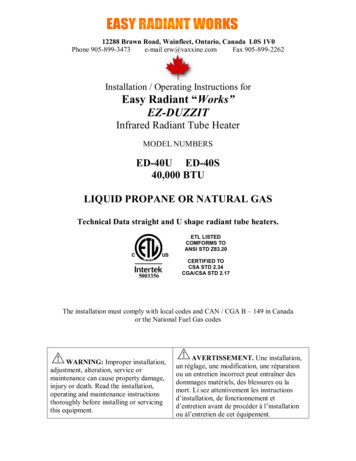
12288 Brawn Road, Wainfleet, Ontario, Canada L0S 1V0Phone 905-899-3473e-mail erw@vaxxine.comFax 905-899-2262Installation / Operating Instructions forEasy Radiant “Works”EZ-DUZZITInfrared Radiant Tube HeaterMODEL NUMBERSED-40U ED-40S40,000 BTULIQUID PROPANE OR NATURAL GASTechnical Data straight and U shape radiant tube heaters.ETL LISTEDCOMFORMS TOANSI STD Z83.205003356CERTIFIED TOCSA STD 2.34CGA/CSA STD 2.17The installation must comply with local codes and CAN / CGA B – 149 in Canadaor the National Fuel Gas codesWARNING: Improper installation,adjustment, alteration, service ormaintenance can cause property damage,injury or death. Read the installation,operating and maintenance instructionsthoroughly before installing or servicingthis equipment.AVERTISSEMENT. Une installation,un réglage, une modification, une réparationou un entretien incorrect peut entraîner desdommages matériels, des blessures ou lamort. Li sez attentivement les instructionsd’installation, de fonctionnement etd’entretien avant de procéder à l’installationou àl’entretien de cet équipement.
FOR YOUR SAFETYIF YOU SMELL GASConsignes De SecuriteSI VOUS SENTEZ UNE ODEUR DE GAZ1. Open windows1. Ouvrez les fenetres2. Do not touch electrical switches, or telephone2. Ne touchez pas aux interrupteurs electriques3. Extinguish any open flame3. Eteignez toute flamme nue4. Immediately call your fuel supplier4. Contactez immediatement compagnie de gaz5. If your gas supplier is not available, call the firedepartment6. Do not attempt to light this or any otherapplicance5. Si votre fournisseur de gaz n’est pas disponible,appeler les pompiers.6. Ne pas tenter d’allumer ceci ou aucun autreappareil.For Indoor Installation only. Not for use in residential dwellingsInstallation a l’interieur seulement. Ne pas installer dans un logement.Manifold Gas Pressures:Natural Gas 3.5” W.C. – L.P. (Propane) 10.0” W.C.Minimum Inlet Pressures:Natural Gas 7” W.C. & L.P. (Propane) 11.5” W.C.Maximum Inlet Pressures:Natural Gas 14.0” W.C. & L.P. (Propane) 14.0” W.C.Electrical: 120VAC / 60 Hz / 1-Ph / 1A3 AMPS STARTING, 1 AMP RUNNING2
CLEARANCES TO COMBUSTIBLESThe clearance to combustible materials represents the minimum distance that must be maintainedbetween the heater and a nearby surface.The stated clearance to combustibles represents a surface temperature of 90 degree Fahrenheit(32 degrees Celsius) above room temperature. Building material with a low heat tolerance maybe subject to degradation of lower temperatures. It is the installer’s responsibility to assure thatadjacent material are not subject to degradation.A warning statement that an overhead heater should be installed so that the minimum clearancesmarked on the heater will be maintained from vehicles parked below the heater.Minimum clearances (inches) from combustibles measured from radiant surface.Clearances are reduced by 1/3, 15 ft (4.6 meters) from the burner.For installation at elevations above 2000 ft (610m), the appliance shall be de-rated 4 percent foreach 1000 ft (305m) of elevation above sea level.ABOVESIDEBACK30M DEAX SIDEAbove/Sommet30M DEAX G.Minimum Clearances to Combustibles/ Escape Libre Minimum Entres LesMateriaux Combustibles30 DEG. ELOWBELOWBELOWThis appliance must be grounded in accordance with ANSI / NFPA 703
Thank you for purchasing the “EZ DUZZIT” residential garage heater. You have purchased either an “S” straightmodel or “U” U-shaped model. Follow the appropriate installation instructions for the model you are installing.“EZ DUZZIT” residential garage heaters are self-contained heatingappliances that require gas supply & 120 V electrical supply. Qualifiedindividuals must do all gas and electrical connections with strict adherence toall applicable codes. The heaters must be vented to the outside (through thewall or roof). Ducting of combustion air from outside is optional, but may beGENERALINSTALLATIONINSTRUCTIONSnecessary incertain applications(see combustionair venting).INSTALLATION INSTRUCTIONSFOR STRAIGHT “S” SERIES HEATER“S” series straight heaters consist of burner, 2-10 ft. (.6 to 3 meters) radiant tubes, 2-10 ft. (.6 to3 meters) reflectors and four plated hangers. For access to controls, remove screw in center ofdoors and swing open.ReflectorHangers Qty. 49 ft. 6 in.The hangers included with the straight model “EZ DUZZIT” heater have two availablesuspension rings. If the reflector is to be flat the hangers should be suspended from the top ring.If the reflectors are to be angled, the hangers should be suspended from the side ring. Using thechain provided, suspend the four hangers from the ceiling ensuring that the radiant tube will beparallel to the floor, with strict adherence to the clearances to combustibles as listed in thismanual and the rating plate on the burner. Suspend the hangers from either the top or side ringon the hanger as desired.Once the hangers are suspended the 3-1/2” dia. radiant tubes can be placed in the hangersensuring that the sight glass is pointing down. Ensure that the enlarged end of the 3-1/2” primarytube, with the setscrew is at the desired location for the burner. Fit the 3-1/2” primary tube intothe enlarged end of the 3-1/2” dia. secondary tube. Install the screw provided through thepredrilled hole in the secondary tube and into the primary tube in order to secure the two tubestogether. With the tubes in place, the reflectors can now be laid into the hangers.Remove the protective plastic cap from the nozzle of the burner and place the nozzle end of theburner into the enlarged end of the radiant tube. Tighten the setscrew so as to secure the burnerinto place.For installation instructions in the United States this appliance must not be installed less than 8ft. (2.4 meters) above the floor. In Canada it cannot be installed less than 7 ft. (2.1 meters) fromthe floor. It must be installed with strict adherence to clearances to combustibles.4
Install thermostat approximately 5’6” (1.6 meters) above floor and not located in the direct ray ofthe heater. Remove the jumper wire on the burner (marked 24 V thermostat) and using 24 Voltwiring connect from terminals on the burner to the thermostat.INSTALLATION INSTRUCTIONS FOR U-SHAPED “U” MODELS“U” shaped models consist of burner, U-shaped 3-1/2” dia. radiant tube heat exchanger, 2hanging brackets and reflectors. For access to controls, remove screw in center of doors andswing open.“U” models must be suspended with the chain provided and suspended at each of the foursuspension points. It should never be lifted or suspended by the burner or reflector. Using thechain provided suspend the radiant tube, so that it is parallel to the floor making sure to complywith necessary clearances to combustibles and clearances to the floor. The length of chain maybe adjusted, so that the radiant tube is flat or angle mounted.Once the radiant tube is hanging in place, slide the reflector into place, so that it is resting in thehanging brackets. Remove the plastic protective cover from the nozzle of the burner and slidethe burner into the enlarged end of the U-shaped heat exchanger. Secure with setscrew provided.For installation in the United States this appliance must not be installed less than 8 ft. (2.4meters) above the floor unless equipped with optional protective grille (available from themanufacturer), in which case it can be installed as low as 6 ft. (1.8 meters) to the floor. InCanada it cannot be installed less than 7 ft. (2.1 meters) from the floor and the protective grille isnot needed. It must be installed with strict adherence to clearances to combustibles.Install thermostat approximately 5’6” (1.6 meters) above floor and not located in the direct ray ofthe heater. Remove the jumper wire on the burner (marked 24 V thermostat) and using 24 Voltwiring connect from terminals on the burner to the thermostat.GAS CONNECTIONA qualified and licensed technician must do all gas piping and connections. All gas piping mustbe done in accordance with all local codes and CAN / CGA B 149 and ANSI standards Z223.15
A 1/8” (.3 cm) NPT plugged tapping accessible for test gauge connection must be suppliedimmediately upstream of the gas supply connection to the heater. A drip leg must be installed inthe gas line at the heater connection.VENTINGAll venting must be in accordance with all applicable codes1. The maximum allowable length of vent pipe is 30 ft. (9.14 meters). This length includesthe combination of inlet air vent for combustion and exhaust venting. THE RADIANTTUBE IS NOT INCLUDED IN THIS MEASUREMENT. For every 90-degree elbow inthe vent system, 5 ft. (1.5 meters) must be deducted from the total allowable length.Horizontal venting must be installed with a 1/4” (3.5 cm) per foot downward slope.2. The exhaust vent terminal must be installed not less than 7 ft. (2.1 meter) above grade.Fresh air seamless air intake duct and screened wall caps are available from your EasyRadiant Works supplier. When installed in a building with a negative air condition,combustion air from outside the negative area is mandatory. Combustion air wall capshall not be installed less than 3 ft. (.9 meters) above grade.3. Type “B” vent must be used for that portion of the vent that passes through acombustible. For through the wall venting, the exhaust vent terminal supplied by EasyRadiant Works MUST be used. The tip of the vent terminal must be a minimum of 16”(40 cm) off the wall. For roof venting a suitably approved Belmont type rain cap must beused. The use of any wall vent terminal other than that supplied by EASY RADIANTwill void warranties. EASY RADIANT WORKS accepts no responsibility for damagescreated by other vent terminals. Exceeding the allowable lengths noted may createcondensation problems and will void Design Certification and the heater warranty.4. If vent pipe with a slip fit connection is used, it must be mechanically secured.Uninsulated vent pipe must not run through unheated spaces.5.Venting must be supported every 3 ft. (.9 meters). Vents for products of combustion shallnot terminate less than 6 ft. (1.8 meters) from inlet air of any other appliance or be lessthan 3 ft. (.9 meters) from any building opening or directly above a gas utility meter.6.The Ez-Duzzit tube system has been approved for vented and un-vented applications.When installed un-vented it must be electrically interlocked to an exhaust fan with an airproving switch. The exhaust fan must provide exhaust in the amount of 300 c.f.m. forevery 100,000 BTU input in Canada and the amount of 400 c.f.m. for every 100,000 BTUinput in the USA. When installed un-vented provision must be made to supply adequatecombustion air from outside the space. Combustion air openings must be in the amountof one (1) square inch (2.5 sq.cm) or more of free area for each 10,000 BTUH. Wheninstalled vented, installations must comply with all governing codes.7. When installed in a large and adequately ventilated space (agricultural building used onlyfor brooding purposes) the heater may be installed un-vented without interlocking, andmay be operated by discharging the combustion products directly into the space, subjectto the approval of the authority having jurisdiction and provided that the maximum inputof the appliance does not exceed 20 BTUH/ft 3 (0.2 kW/m3) of the space in which the6
heater is located. An appliance designed to produce a controlled atmosphere need not besubject to these conditions.8. Vents for products of combustion shall not terminate less than 3 ft (.9 meters) from acombustion air inlet of any other appliance, or be less than 3 ft (.9 meters) from abuilding opening or be directly above a gas utility meter or service regulator.9. The exhaust vent terminal must be installed not less than 7 feet (2.1 meter) above grade.NOTE: When located in a building with a negative air condition, or in a dusty or dirtyatmosphere such as a wood working shop, poultry barn or foundries, combustion air fromoutside the negative or dirty area to the burner is mandatory. The combustion air supplyshould be minimum 4-inch (10.1 cm) diameter seamless air duct, connected to fresh airadapter provided on combustion air blower. All joints or seams shall be sealed to preventleaks. Horizontal vent systems shall slope downwards not less than 1/4” (5.5 cm)per footfrom the start of the vent system to the vent terminal.10.All venting should be inspected prior to each heating season.COMBUSTION AIR VENTINGWhen located in a building with a negative air condition or in a dusty or dirty atmosphere such asa woodworking shop, poultry barn or foundry, venting of combustion air to the burner fromoutside the negative or dirty area is mandatory. The combustion air supply should be a minimum4-inch diameter seamless air duct, connected to fresh air adapter provided on the combustion airblower. All joints or seams shall be sealed to prevent leakage. The maximum length ofcombustion air inlet shall comply with the “venting of products of combustion” as described inthis manual.MINIMUM CLEARANCES TO COMBUSTIBLESClearances to combustibles shall be measured from the top surface of the combustible floor,carpet or tile. This appliance must be located away from furniture and draperies. The heatexchanger will reach high temperatures and care must be taken to prevent burns. Childrenshould be carefully supervised when in the same room as this heater. Clearances to combustiblesmust always be maintained. Do not touch heat exchanger while heater is in operation.Clearances tocombustibles fromradiant tubeAll ModelsTop (AboveReflector)Back (Back of angledreflector)4” (10 cm)4” (10 cm)Sides18” (46 cm)Below(Reflectors flat)36” (92 cm)Below (Reflectorsangled)30” (76 cm)7
Minimum Clearances to Combustibles/ Escape Libre Minimum Entres LesMateriaux Combustibles30 DEG. ANGLEHORIZONTAL/HORIZONTALEABOVESIDEBACK30M DEAX G.ABOVESIDE.30M DEAX THIS HEATER MUST BE INSTALLED AND SERVICED BY A TRAINED GAS SERVICETECHNICIAN ONLY. READ AND UNDERSTAND THESE INSTRUCTIONSTHOROUGHLY BEFORE ATTEMPTING TO INSTALL, OPERATE OR SERVICE THEEASY RADIANT WORKS HEATER. FAILURE TO COMPLY WITH THESE WARNINGSAND INSTRUCTIONS, AND THOSE ON THE HEATER COULD RESULT IN PERSONALINJURY, DEATH, FIRE, ASPHYXIATION, AND / OR PROPERTY DAMAGE.DO NOT STORE OR USE GASOLINE OR OTHER FLAMMABLE VAPOURS ANDLIQUIDS IN THE VICINITY OF THIS OR ANY OTHER GAS FIRED APPLIANCETHIS APPLIANCE MAY HAVE SHARP EDGES AND CORNERS, WEAR PROTECTIVECLOTHING SUCH AS GLOVES AND PROTECTIVE EYE WEAR WHEN SERVICINGTHIS OR ANY OTHER APPLIANCE.INSTRUCTIONS MUST REMAIN WITH THE UNIT.APPLICATIONIt is beyond the scope of these instructions to consider all conditions that may be encountered.Installation must conform with all local building codes or, in the absence of local codes, to theNational Fuel Gas Code, ANSI Z223.1/NFPA54 in the U.S.A. or the Natural Gas and PropaneInstallation Code, CSA B149.1 in Canada. The latest edition Electrical Code ANSI/NFPA N0 70in the U.S.A. and PART 1 CSA C22.1 in Canada must also be observed.Installation of a gas fired tube heater must conform to all heating installation design proceduresincluding clearance to combustibles, connection to the gas and electrical supplies, andventilation.This heater is not for installation in a Class 1 or Class 2 explosive environment, nor a residence.If installation of this equipment is in question, consult with local authorities having jurisdiction(Fire Marshall, labour department, insurance underwriter, or others).8
Revisions to codes and/or standards may require revision to equipment and installationprocedures. In case of discrepancy, the latest codes, standards, and installation manual will takepriority over prior releases.WARNINGWhere there is the possibility of exposure to combustible airborne materials or vapour, consultthe local fire inspector's office, the fire insurance carrier or other applicable authorities forapproval of the proposed installation.Do not use in an atmosphere containing halogenated hydrocarbons or other corrosive chemicals.Some compounds in the environment can cause an accelerated rate of corrosion to the heatexchanger.The heater manufacturer cannot anticipate all types and chemical composition of possiblecontaminants at project sites. Confer with project site safety, health and engineering staff and/orlocal authorities having jurisdiction such as the Fire Marshall and Department of Labour forpossible contaminants and any conflict with the installation of hot surface heating equipment.WARNINGHEATER EXPANSIONIt is normal condition that during heat-up and cool-down a tube heater will expand and contract.Allowances for heater expansion must be made in the gas connection, venting and combustionair ducting. Consider that the heater will expand in length as much as ½ inch (12.5mm) or morefor every 10 ft (3 m) of system length. Typically, the greater the firing rate, the greater theexpansion.WARNINGGAS CONNECTIONImproper installation, connection, or adjustment can result in property damages, toxic gases,asphyxiation, injury and death. Using an approved flexible gas connector in the USA and RubberType 1 hose connector in Canada, the gas supply to the heater must be connected and tested inaccordance with all local, state, provincial, and national codes (ANSI Z223.1/NFPA 54 in USA:B149.1 in Canada) and as indicated in the manual.WARNINGVENTING9
Inadequate venting of a heater may result in asphyxiation, carbon monoxide poisoning, injury ordeath. The heater may be directly or indirectly vented from the space. Venting must be inaccordance with all local, state, provincial, and national codes (ANSI Z223.1/NFPA 54 in USA;B149.1 in Canada) and as indicated in this manual.\WARNINGSTART-UP SMOKE CONDITIONDuring start up, the heating of material coatings used in the production process of tubes andreflectors will create smoke during the initial period of operation. This condition is normal andtemporary. Ensure that there is sufficient ventilation to adequately clear any smoke from thespace. Notify site and safety personnel to ensure that alarm systems are not unduly activated.WARNINGCLEARANCES TO COMBUSTIBLESA warning statement that an overhead heater should be installed so that the minimum clearancesmarked on the heater will be maintained from vehicles parked below the heaterLocation of flammable or explosive objects, liquids or vapours close to the heater may cause fireor explosion and result in property damage, injury or death. Do not use, store or locateflammable or explosive objects, liquids or vapours in proximity of the heater.The clearance to combustible material represents the minimum distance that must be maintainedbetween the outer heater surface and a nearby surface. The stated clearance to combustiblerepresents a surface temperature of 90 degrees F (50 degrees C) above room temperature. It isthe installer's responsibility to ensure that building materials with a low heat tolerance, whichmay degrade at lower temperatures, are protected to prevent degradation.Minimum 24” (61 cm) must be provided at the centre of the appliance for burner servicing.When venting through a wall the vent terminal must be located at least 7.0 ft (2.1m) above grade.This appliance must be mounted at least 7 ft (2.1m) above the floor in Canada, and 8 ft (2.4m)above the floor in the U.S.10
Minimum clearances (inches and cm) from combustibles measured from radiant surface. Theclearances are reduced by 1/3, 15 ft (4.6 meters) from the burner.INSTALLATION IN COMMERCIAL AIRCRAFT HANGARSLow intensity radiant tube heaters are suitable for use in aircraft hangars when installed inaccordance with the latest edition of the Standard for Aircraft hangars, ANSI/NFPA No. 409 inthe USA, or the Canadian Natural Gas and Propane Installation Code, B149.1A minimum clearance of 10 ft (3m) above either the highest fuel storage compartment or thehighest engine enclosure of the highest aircraft, which may occupy the hangar. The clearance tothe bottom of the heater shall be measured from the upper surface of either the fuel storagecompartment or the engine enclosure; whichever is higher from the floor.A minimum clearance of 8 ft (2.4m) must be maintained from the bottom of the heater to thefloor in other sections of the aircraft hangar, such as offices and shops, which communicate withareas for servicing or storage. For proper mounting clearances, refer to the clearances tocombustibles in these installation instructions.Heaters must be located where they are protected from damage to aircraft and other objects, suchas cranes and movable scaffolding.Heaters must be located so as to be accessible for servicing and adjustment.INSTALLATION IN COMMERCIAL GARAGES AND PARKINGSTRUCTURESLow intensity heaters are suitable for use in commercial garages when installed in accordancewith the latest edition of the Standard for Parking Structures, ANSI/NFPA 88A, or the Standardfor Repair Garages ANSI/NFPA No. 88B, or the Canadian Natural Gas and Propane InstallationCode, B149.1WARNINGINSTALLATIONS OTHER THAN SPACE HEATING11
Use for process or other applications that are not space heating will void the products warranty.Process application requires field inspection and/or certification by local authorities havingjurisdiction.IMPORTANTSingle or multiple heater placement must be such that continuous operation of heater(s) will notcause combustible material or materials in storage to reach a temperature in excess of ambienttemperature plus 90 degrees Fahrenheit (50 degrees Celsius).It is the installer’s responsibility to ensure that building materials with a low heat tolerance,which may degrade at lower temperatures, are protected to prevent degradation. Refer toClearance to Combustibles information in these installation instructions.GENERAL INSTALLATION PROCEDUREPRE-INSTALLATION SURVEYIt is recommended that a full heating design, including a heat loss calculation be conducted.Heater sizing and placement must consider available mounting height, sources of heat loss, andclearances to combustibles with respect to stored material, moveable objects (cranes, vehicles,lifts, overhead doors, etc) sprinkler systems, and other obstructions on the site. Considerationmust also be given to vent / duct placement and the allowable combined lengths of vent and duct.1. Carefully survey the area to be heated and place the burner and combustion chamber inthe coldest area if possible.2. The heater shall be hung in such a fashion so as to conform with the clearances tocombustibles described on the name plate.3. Clearances to combustibles must be maintained from vehicles parked below.4. Adequate clearances must be maintained for installation in public garages and airplanehangar.5. It should be located with respect to building construction and equipment, so as to providesufficient clearances and accessibility for servicing.6. The installation must comply with local codes and CAN/CGA B-149 in Canada or theNational Fuel Gas codes ANSI Z 223.1 in the United States.ELECTRICAL120V, 60 HZ, 3 AMPS STARTING, 1 AMP RUNNINGIgnition System:120 Volt / Hot surface igniterThermostat control:Heaters are designed for compatibility with either 120 Volt thermostat controllers or 24 Voltthermostat controllers. For use with 120 Volt controllers, the heater must be plugged into a“switched” 120 Volt duplex receptacle, where the receptacle is switched by the thermostatcontroller. Heating zones may be established where one 120 Volt thermostat, controls more thanone heater, provided the total heater electrical load does not exceed the maximum allowableamperage on the circuit.12
For 24 volt thermostat control plug the heater into a 120 Volt duplex receptacle. Remove thejumper wire on the control box marked “24 Volt thermostat” and connect the thermostat wire tothe terminals. Ensure that if the thermostat has a heat anticipator, that the heat anticipator is setat maximum. When using a 24 Volt thermostat, only one heater may be controlled by onethermostat.1. Electrical installation must be grounded in accordance with CSA standard C22.1 part 1 inCanada or The National Electrical code ANSI NFPA 70 (latest edition) in the UnitedStates.2. Polarity of line voltage and neutral wires must be maintained.3. The total load of all heaters in a circuit must be considered not to overload the circuit.SUSPENDING THE SYSTEMInadequate or improper suspension of the tube heater can result in collapse of the system, propertydamage, and personal injury or death. It is the installer’s responsibility to ensure that the hardware andstructural supports from which the heater is suspended are sound and of adequate strength to support theweight and expansion forces of the heater.Consider that the heater will expand in length as much as ½ inch (12.7) or more for every 10 ft(3 m) of system length. Typically, the greater the firing rate, the greater the expansion.Survey the available structural supports, considering the system configuration and heat requirements ofthe area to establish the optimum heater location. Locating a heater directly under joists or beams, orinstalling supplemental steel support rail or angle iron can substantially reduce labour and materials.Hardware with a minimum 60 lbs (27 kg) workload must be used at each heater suspension point.Connect the structure using typical hardware as illustrated below or by other mechanically sound means.13
REFLECTOR EXTENSIONSReflector extensions may be installed on one side or both sides of the reflector. Reflectorextensions are 10 ft long x 9”. Drill 3 holes and insert S hooks.GAS PIPING1. All gas piping and connections shall be made in accordance with local codes andCAN/CGA B-149 or ANSI standard Z223.1.2. Connect the burner to gas supply with flexible gas connector.3. A drip leg must be installed in the gas line at the heater inlet connection tee followed by apipe drop to the heater. Failure to provide a drip leg could result in condensation andforeign matter passing into the gas valve. Failure to install a drip leg in the gas line cancause property damage, injury or death and will void the heater warranty.14
CAUTION: Correct inlet pressure is vital to efficient operation of heaters. Refer to the ratingplate and, if necessary, consult Gas Company.WARNINGNever use a match or other flame to test for gas leaks. Use soap and water solution to checkfor leaks to all connections and joints and if bubbles appear, leaks have been detected andmust be corrected. Never operate the heater with leaking connections. The supply system15
should be checked first with heater turned off followed by another check with the heater on.The supply gas pressure must be checked with all heaters in operation.GAS SUPPLY, HEATER EXPANSION, AND FLEXIBLE GASCONNECTIONThe gas supply must be installed to the heater using:In USA an approved Stainless Steel Flexible Gas Connector certified for use on an infraredradiant tube heater (ANSI Z21.24 CSA 6.10)In Canada an approved Type 1 Hose Gas Connector (CAN/CGA 8.1)The heater must be isolated from the gas supply piping system by closing its individualmanual shut off valve (field supplied) during any pressure testing of the gas supply pipingsystem.Compensation for normal gas supply pipe expansion, and radiant tube heater expansion mustbe provided. All piping must conform to local codes.Provide a 1/8 in (3.2mm) NPT plugged tapping, accessible for test gauge connection,immediately upstream of the gas supply connection to the heater.Test for leaks. All gas piping and connections must be tested for leaks after the installation iscompleted.Apply soapsuds solution to all connections and joints and if bubbles appear, leaks have beendetected and must be corrected. Do not use a match or open flame of any kind to test forleaks. Never operate the heater with leaking connections.The supply systems should be checked first with the heater turned off followed by anothercheck with the heater turned on. The supply gas pressure must be checked with all heaters inoperation.WARNINGThis heater will expand in length as it heats up. It is a normal condition that during heat-upand cool-down a tube heater will expand and contract. Allowances for heater expansion mustbe made in the gas connection, venting and combustion air ducting. Improper installation,alteration, or adjustment can result in property damage, injury or death.16
The BTU input and the tube length determine the overall expansion that occurs. A typicalinfrared tube installation will expand toward both the burner and the vent end.To allow heater expansion the gas supply must be installed using:In the USA: a stainless steel flexible gas connector certified for use on an infrared radianttube heater (ANSI Z21.24 CSA 6.10)In Canada: a Type 1 hose connector (CAN/CGA 8.1). Also the flue vent, and combustion airintake (if used) must be installed in such a manner that the normal expansion of the heaterwill be accommodated.VENTING OPTIONS17
LISTED 70AC1180AC1200AC1220AC1350AC1085Ind. Thermostat 120VAgricultural ThermostatRemote ThermostatAgricultural Thermostat24V ThermostatFlexible Gas ConnectorOutside Air AdapterRemote ThermostatOutside Air Wall CapCombustion Air Flex Duct4x4x6 Tee90 degree Elbow180 degree BendWall ThimbleBrooder Exhaust Cap 4" dia4” Wall Spout Exhaust Cap24V ThermostatFresh Air Package (Cap, Duct, Clamps)Reflector SupportsAttic Air Intake with adapter18
EASY RADIANT WORKS ACCESSORIESEASY RADIANT WORKS ACCESSORIES19
OPERATING SEQUENCEThe Easy Radiant gas burner is a very simple device. The normal sequence of events duringignition and operation of the burner is as follows:1. The heater is energized by m
Installation / Operating Instructions for Easy Radiant "Works" EZ-DUZZIT Infrared Radiant Tube Heater MODEL NUMBERS ED-40U ED-40S 40,000 BTU LIQUID PROPANE OR NATURAL GAS Technical Data straight and U shape radiant tube heaters. 5003356 ETL LISTED COMFORMS TO ANSI STD Z83.20 CERTIFIED TO CSA STD 2.34 CGA/CSA STD 2.17