Transcription
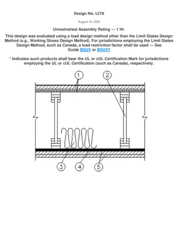
Design No. L570August 14, 2020Unrestrained Assembly Rating — 1 Hr.This design was evaluated using a load design method other than the Limit States DesignMethod (e.g., Working Stress Design Method). For jurisdictions employing the Limit StatesDesign Method, such as Canada, a load restriction factor shall be used — SeeGuide BXUV or BXUV7* Indicates such products shall bear the UL or cUL Certification Mark for jurisdictionsemploying the UL or cUL Certification (such as Canada), respectively.
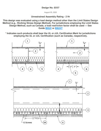
1. Flooring System — The flooring system shall consist of one of the following:System No. 1Subflooring — Nom 19/32 in. thick wood structural panels installed perpendicular to the joists with end jointsstaggered. Plywood or panels secured to joists with construction adhesive and No. 6d ringed shank nails, spaced 12 in.OC along each joist. Staples having equal or greater withdrawal and lateral resistance strength may be substituted forthe 6d nails.Vapor Barrier — (Optional) — Nom 0.030 in. thick commercial asphalt saturated felt.Finish Floor — Min 1 by 4 in. T & G lumber installed perpendicular to the joists, or min 15/32 in. thick wood structuralpanels, min grade "Underlayment" or "Single-Floor". Face grain of plywood or strength axis of panel to beperpendicular to joists with joints staggered.System No. 2Subflooring — Nom 19/32 in. thick wood structural panels installed perpendicular to the joists with end jointsstaggered. Plywood or panels secured to joists with construction adhesive and No. 6d ringed shank nails, spaced 12 in.OC along each joist. Staples having equal or greater withdrawal and lateral resistance strength may be substituted forthe 6d nails.Vapor Barrier — (Optional) — Nom 0.010 in. thick commercial asphalt saturated felt.Finish Flooring — Floor Topping Mixture* — Min 3/4 in. thickness of floor topping mixture having a minimumcompressive strength of 1800 psi. Refer to manufacturer's instructions accompanying the material for specific mixdesign.UNITED STATES GYPSUM CO — Types LRK, HSLRK, CSD
LATICRETE SUPERCAP L L C — Types LRK, HSLRKUSG MEXICO S A DE C V — Types LRK, HSLRK, CSDFloor Mat Materials* — (Optional) — Floor mat material loose laid over the subfloor. Refer to manufacturer'sinstructions regarding the minimum thickness of floor topping over each floor mat material.UNITED STATES GYPSUM CO — Types SAM, LEVELROCK Brand Sound Reduction Board, LEVELROCK Brand FloorUnderlayment SRM-25Alternate Floor Mat Materials* — (Optional) — Floor mat material loosely laid over the subfloor. Refer tomanufacturer's instructions regarding minimum thickness of floor topping over floor mat.GRASSWORX L L C — SC TypesSystem No. 3Subflooring — Nom 19/32 in. thick wood structural panels installed perpendicular to the joists with end jointsstaggered. Plywood or panels secured to joists with construction adhesive and No. 6d ringed shank nails, spaced 12 in.OC along each joist. Staples having equal or greater withdrawal and lateral resistance strength may be substituted forthe 6d nails.Vapor Barrier — (Optional) — Nom 0.030 in. thick commercial asphalt saturated felt.Finish Flooring — Floor Topping Mixture* — Min 3/4 or 1 in. thickness of floor topping mixture for 19/32 or 15/32in. thick wood structural panels respectively, having a min compressive strength of 1000 psi. Refer to manufacturer'sinstructions accompanying the material for specific mix design.ACG MATERIALS — AccuCrete types NexGen, Green, Prime, B, M, and PrePour, AccuRadiant, AccuLevel types G40,G50 and SD30.Alternate Floor Mat Material* — (Optional) — Floor mat material nominal 2 - 9.5 mm thick loose laid over thesubfloor. Floor topping shall be a min of 3/4 in. or 1 in. thick for 19/32 or 15/32 in. thick wood structural panelsrespecitively.ACG MATERIALS — AccuQuiet types P80, C40, D13, D-18, D25, DX38, EM.125, EM.125S, EM.250, EM.250S, EM.375,EM.375S, EM.750, and EM.750S.
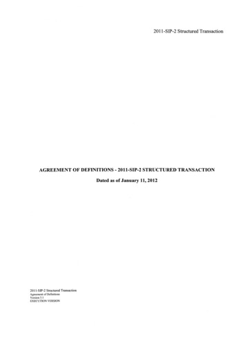
System No. 4Structural Cement-Fiber Units* — Nom 3/4 in. thick, with long edges tongue and grooved. Long dimension ofpanels to be perpendicular to joists with end joints staggered a min of 2 ft and centered over the joists. Panels securedto joists with 1-5/8 in. long No. 8 self-drilling, self-countersinking steel screws spaced a max of 12 in. OC in the fieldwith a screw located 1 in. and 2 in. from each edge, and 8 in. OC on the perimeter with a screw located 2 in. from eachedge, located 1/2 in. from the side edges of the panel.UNITED STATES GYPSUM CO — Types STRUCTO-CRETE, USGSPSystem No. 5Subflooring — Min 19/32 in. thick wood structural panels, min grade "C-D" or "Sheathing". Face grain of plywood orstrength axis of panels to be perpendicular to the joists with joints staggered.Vapor Barrier — (Optional) — Commercial asphalt saturated felt, 0.030 in. thick.Vapor Barrier — (Optional) — Nom 0.010 in. thick commercial rosin-sized building paper.Finish Flooring* — Min 3/4 in. thickness of any Floor Topping Mixture bearing the UL Classification Marking as to FireResistance. See Floor- and Roof-Topping Mixtures (CCOX) category for names of Classified Companies.Floor Mat Materials* — (Optional) — Nom. 1/4 in. thick loose laid over the subfloor. Floor topping thickness shall bea minimum of 3/4 in.KEENE BUILDING PRODUCTS CO INC — Type Quiet Qurl 55/025 and Quiet Qurl 55/025 NAlternate Floor Mat Materials* — (Optional) — Floor mat material Nom. 3/8 in. thick loose laid over the subfloor.Floor topping thickness shall be a minimum of 1 in.KEENE BUILDING PRODUCTS CO INC — Type Quiet Qurl 60/040 and Quiet Qurl 60/040 NAlternate Floor Mat Materials* — (Optional) — Floor mat material Nom. 3/4 in. thick loose laid over the subfloor.Floor topping thickness shall be a minimum of 1-1/2 in.KEENE BUILDING PRODUCTS CO INC — Type Quiet Qurl 65/075, Quiet Qurl 65/075 NAlternate Floor Mat Materials* — (Optional) — Floor mat material Nom. 1/8 in. thick loose laid over the subfloor.Floor topping thickness shall be a minimum of 3/4 in.KEENE BUILDING PRODUCTS CO INC — Type Quiet Qurl 52/013 and Quiet Qurl 52/013 NAlternate Floor Mat Materials* — (Optional) — Floor mat material Nom. 1/4 in. entangled net core with acompressible fabric attached to the bottom loose laid over the subfloor. Floor topping thickness shall be a minimumof 1 in.
KEENE BUILDING PRODUCTS CO INC — Quiet Qurl 55/025 MT and Quiet Qurl 55/025 N MTSystem No. 6Subflooring — Nom 19/32 in. thick wood structural panels installed perpendicular to the joists with end jointsstaggered. Plywood or panels secured to joists with construction adhesive and No. 6d ringed shank nails, spaced 12 in.OC along each joist. Staples having equal or greater withdrawal and lateral resistance strength may be substituted forthe 6d nails.Finish Flooring - Floor Topping Mixture* — Min 3/4 in. thickness of floor topping mixture having a min compressivestrength of 1100 psi. Mixture shall consist of 6.8 gal of water to 80 lbs of floor topping mixture to 1.9 cu ft of sand.HACKER INDUSTRIES INC — Firm-Fill Gypsum Concrete, Firm-Fill 2010, Firm-Fill 3310, Firm-Fill 4010, Firm-Fill HighStrength and Gyp-Span RadiantMetal Lath — (Optional) — For use with 3/8 in. (10 mm) floor mat materials, 3/8 in. expanded steel diamond mesh,3.4 lbs/sq yd placed over the floor mat material. Hacker Floor Primer to be applied prior to the placement of the metallath. When metal lath is used, floor topping thickness a nom 1-1/4 in. over the floor mat.Floor Mat Materials* — (Optional) Floor mat material nom 5/64 in. (2 mm) thick adhered to subfloor with HackerFloor Primer. Primer to be applied to the surface of the mat prior to the placement of a min 1 in. of floor-toppingmixture.HACKER INDUSTRIES INC — Type Hacker Sound-Mat.Alternate Floor Mat Materials — (Optional) — Floor mat material nom 1/4 in. (6 mm) thick adhered to subfloor withHacker Floor Primer. Primer to be applied to the surface of the mat prior to the placement of a min 1-1/4 in. (32 mm)of floor-topping mixture.HACKER INDUSTRIES INC — Type Hacker Sound-Mat II.Alternate Floor Mat Materials — (Optional) — Floor mat material nom 1/8 in. (3 mm) thick loose laid over thesubfloor. Floor topping thickness shall be a min of 3/4 in. (19 mm)HACKER INDUSTRIES INC — FIRM-FILL SCM 125Alternate Floor Mat Materials — (Optional) — Floor mat material nom 1/4 in. (6 mm) thick loose laid over thesubfloor. Floor topping thickness shall be a min of 1 in. (25 mm)HACKER INDUSTRIES INC — Type FIRM-FILL SCM 250, Quiet Qurl 55/025
Alternate Floor Mat Materials — (Optional) — Floor mat material nom 3/8 in. (10 mm) thick loose laid over thesubfloor. Floor topping thickness shall be a min of 1-1/4 in. (32 mm)HACKER INDUSTRIES INC — FIRM-FILL SCM 400, Quiet Qurl 60/040Alternate Floor Mat Materials — (Optional) — Floor mat material nom 3/4 in. (19 mm) thick loose laid over thesubfloor. Floor topping thickness shall be a min of 1-1/2 in. (38 mm)HACKER INDUSTRIES INC — Type FIRM-FILL SCM 750, Quiet Qurl 65/075System No. 7Subflooring — Nom 19/32 in. thick wood structural panels installed perpendicular to the joists with end jointsstaggered. Plywood or panels secured to joists with construction adhesive and No. 6d ringed shank nails, spaced 12 in.OC along each joist. Staples having equal or greater withdrawal and lateral resistance strength may be substituted forthe 6d nails.Finish Floor — Mineral and Fiber Board* — Min 1/2 in. thick, supplied in sizes ranging from 3 ft by 4 ft to 8 ft by 12ft. All joints to be staggered a min of 12 in. with adjacent sub-floor joints.HOMASOTE CO — Type 440-32 Mineral and Fiber BoardSystem No. 8Subflooring — Nom 19/32 in. thick wood structural panels installed perpendicular to the joists with end jointsstaggered. Plywood or panels secured to joists with construction adhesive and No. 6d ringed shank nails, spaced 12 in.OC along each joist. Staples having equal or greater withdrawal and lateral resistance strength may be substituted forthe 6d nails.Vapor Barrier — (Optional) — Nom 0.030 in thick commercial asphalt saturated felt.Finish Flooring - Floor Topping Mixture* — Min 3/4 in. thickness of floor topping mixture having a min compressivestrength of 1500 psi. Refer to manufacturer's instructions accompanying the material for specific mix design.MAXXON CORP — Type Maxxon Standard and Maxxon High StrengthFloor Mat Materials* — Floor mat material loose laid over the subfloor. Refer to manufacturer's instructionsregarding the minimum thickness of floor topping over each floor mat material.MAXXON CORP — Type Encapsulated Sound Mat.Floor Mat Reinforcement — (Optional) Refer to manufacturer's instructions regarding minimum thickness of floortopping for use with floor mat reinforcement.
Metal Lath — (Optional) 3/8 in. expanded galvanized steel diamond mesh, 3.4 lbs/sq yd loose laid over the floor matmaterial.Fiber Glass Reinforcement — (Optional) 0.015 in. thick PVC coated non-woven fiberglass mesh, 0.368 lbs./sq. ydloose laid over the floor mat material.System No. 9Subflooring — Nom 19/32 in. thick wood structural panels installed perpendicular to the joists with end jointsstaggered. Plywood or panels secured to joists with construction adhesive and No. 6d ringed shank nails, spaced 12 in.OC along each joist. Staples having equal or greater withdrawal and lateral resistance strength may be substituted forthe 6d nails.Vapor Barrier — (Optional) Nom 0.030 in. thick commercial asphalt saturated felt.Finish Flooring — Floor Topping Mixture* — Min 3/4 in. thickness of floor topping mixture having a minimumcompressive strength of 1500 psi. Refer to manufacturer's instructions accompanying the material for specific mixdesign.FORMULATED MATERIALS LLC — Types FR-25, FR-30, and SiteMixAlternate Floor Mat Material* — (Optional) Floor mat material nominal 2 - 9.5 mm thick loose laid over the subfloor.Floor topping thickness shall be a minimum of 3/4 in.FORMULATED MATERIALS LLC — Types M1, M2, M3, Elite, Duo, R1, and R2System No. 10Subflooring — Min 19/32 in. thick wood structural panels, min grade "C-D" or "Sheathing". Face grain of plywood orstrength axis of panels to be perpendicular to the joists with joints staggered.Vapor Barrier — (Optional) — Commercial asphalt saturated felt, 0.030 in. thick.Vapor Barrier — (Optional) — Nom 0.010 in. thick commercial rosin-sized building paper.Finish Flooring* — Min 3/4 in. thickness of any Floor Topping Mixture bearing the UL Classification Marking as to FireResistance. See Floor- and Roof-Topping Mixtures (CCOX) category for names of Classified Companies.Floor Mat Materials* — (Optional) — Nom 3/32 in. thick loose laid over the subfloor. Floor topping thickness shall bea minimum of 3/4 in.PLITEQ INC — Type GenieMat RST02Floor Mat Materials* — (Optional) — Nom 3/16 in. thick loose laid over the subfloor. Floor topping thickness shall bea minimum of 3/4 in.PLITEQ INC — Type GenieMat FF03NP
Floor Mat Materials* — (Optional) — Nom 1/4 in. thick loose laid over the subfloor. Floor topping thickness shall bea minimum of 3/4 in.PLITEQ INC — Type GenieMat FF06Floor Mat Materials* — (Optional) — Nom 3/8 in. thick loose laid over the subfloor. Floor topping thickness shall bea minimum of 1 in.PLITEQ INC — Type GenieMat FF10Floor Mat Materials* — (Optional) — Nom 3/4 in. thick loose laid over the subfloor. Floor topping thickness shall bea minimum of 1-1/2 in.PLITEQ INC — Type GenieMat FF17Floor Mat Materials* — (Optional) — Nom 1 in. thick loose laid over the subfloor. Floor topping thickness shall be aminimum of 1-1/2 in.PLITEQ INC — Type GenieMat FF25System No. 11Subflooring — Nom 19/32 in. thick wood structural panels installed perpendicular to the joists with end jointsstaggered. Plywood or panels secured to joists with construction adhesive and No. 6d ringed shank nails, spaced 12 in.OC along each joist. Staples having equal or greater withdrawal and lateral resistance strength may be substituted forthe 6d nails.Vapor Barrier — (Optional) — Nom 0.030 in. thick commercial asphalt saturated felt.Finish Flooring — Floor Topping Mixture* — Min 3/4 or 1 in. thickness of floor topping mixture for 19/32 or 15/32in. thick wood structural panels respectively, having a min compressive strength of 1000 psi. Refer to manufacturer'sinstructions accompanying the material for specific mix design.DEPENDABLE LLC — GSL M3.4, GSL K2.6, GSL-CSD or GSL RHFloor Mat Materials* — (Optional) — Nom. 1/4 in. thick loose laid over the subfloor. Floor topping thickness shall bea minimum of 3/4 in.KEENE BUILDING PRODUCTS CO INC — Type Quiet Qurl 55/025 and Quiet Qurl 55/025 NAlternate Floor Mat Materials* — (Optional) — Floor mat material Nom. 3/8 in. thick loose laid over the subfloor.Floor topping thickness shall be a minimum of 1 in.KEENE BUILDING PRODUCTS CO INC — Type Quiet Qurl 60/040 and Quiet Qurl 60/040 N
Alternate Floor Mat Materials* — (Optional) — Floor mat material Nom. 3/4 in. thick loose laid over the subfloor.Floor topping thickness shall be a minimum of 1-1/2 in.KEENE BUILDING PRODUCTS CO INC — Type Quiet Qurl 65/075, Quiet Qurl 65/075 NAlternate Floor Mat Materials* — (Optional) — Floor mat material Nom. 1/8 in. thick loose laid over the subfloor.Floor topping thickness shall be a minimum of 3/4 in.KEENE BUILDING PRODUCTS CO INC — Type Quiet Qurl 52/013 and Quiet Qurl 52/013 NAlternate Floor Mat Materials* — (Optional) — Floor mat material Nom. 1/4 in. entangled net core with acompressible fabric attached to the bottom loose laid over the subfloor. Floor topping thickness shall be a minimumof 1 in.KEENE BUILDING PRODUCTS CO INC — Quiet Qurl 55/025 MT and Quiet Qurl 55/025 N MTSystem No. 12Subflooring — Nom 19/32 in. thick wood structural panels installed perpendicular to the joists with end jointsstaggered. Plywood or panels secured to joists with construction adhesive and No. 6d ringed shank nails, spaced 12 in.OC along each joist. Staples having equal or greater withdrawal and lateral resistance strength may be substituted forthe 6d nails.Finish Flooring* — Floor Topping Materials — Min 3/4 in. to 1-1/2 in. thickness of any Floor Topping Mixturebearing the UL Classification Marking as to Fire Resistance with a minimum compressive strength of 1500 psi.See Floor- and Roof-Topping Mixtures (CCOX) category for names of Classified Companies.Floor Mat Materials* — (Optional) — Floor mat material nom 1/8 in. to 3/4 in. thick. Loose laid over the subfloor.When used, Acousti-flor CSM (crack suppression mat) is loose laid over the floor mat material. Floor topping materialthickness is dependent on thickness of floor mat used.WALFLOR INDUSTRIES INC — Type Acousti-flor, Acousti-flor CSM. Floor topping thickness depends on productsused as follows:Acousti-flor (1/8 in. thick) - Floor topping thickness shall be a minimum of 3/4 in.Acousti-flor (1/4 in. thick) - Floor topping thickness shall be a minimum of 1 in.Acousti-flor (3/8 in. thick) - Floor topping thickness shall be a minimum of 1 in.Acousti-flor (3/4 in. thick) - Floor topping thickness shall be a minimum of 1-1/2 in.Metal Lath — (Optional) — Expanded steel diamond mesh, 2.5 lb / sq yd loose laid over floor mat material.Fiberglass Mesh Reinforcement — (Optional) — Coated non-woven glass fiber mesh grid loose laid over floor matmaterial.
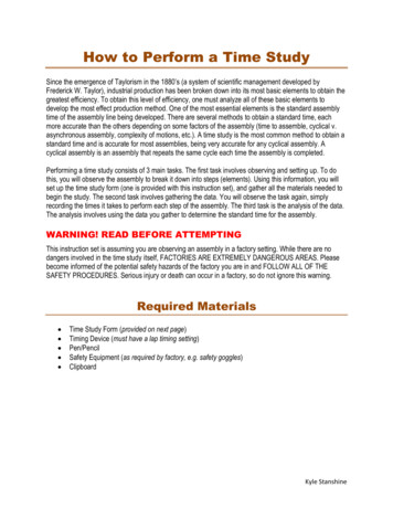
System No. 13Structural Cement-Fiber Units* — For use with UNITED STATES GYPSUM CO gypsum boards only. Nom 3/4 in.thick, with long edges tongue and grooved. Long dimension of panels to be perpendicular to wood trusses with endjoints staggered a min of 2 ft and centered over the trusses. Panels secured to wood trusses with 1-5/8 in. long, No. 8,self- countersinking wood screw spaced a max of 12 in. OC in the field with a screw located 1 in. and 2 in. from eachedge, and 8 in. OC on the perimeter with a screw located 2 in. from each edge, located 1/2 in. from the end edges ofthe panel.UNITED STATES GYPSUM CO — Types STRUCTO-CRETE, USGSPSystem No. 14Subflooring — Nom 19/32 in. thick wood structural panels installed perpendicular to the joists with end jointsstaggered. Plywood or panels secured to joists with construction adhesive and No. 6d ringed shank nails, spaced 12 in.OC along each joist. Staples having equal or greater withdrawal and lateral resistance strength may be substituted forthe 6d nails.Finish Flooring - Floor Topping Mixture* — Min 1 in. thickness of floor topping mixture having a min compressivestrength of 4500 psi. Refer to manufacturer's instructions accompanying the material for specific mix design.SIKA DEUTSCHLAND GMBH — Type SCHONOX AP Rapid PlusSystem No. 15Subflooring — Building Units* — Nom. 1-1/2 in. thick T & G laminated composite plywood sub-floor panels to beperpendicular to the trusses with end joints staggered 4 ft. End joints centered over top chord of trusses. Subfloorpanels secured to trusses with construction adhesive and #8 by 3 in. wood screws spaced 12 in. OC in the field and 6in. OC at the end joints.RSP INDUSTRIES INC — SAP boardSystem No. 16Subflooring — Nom 19/32 in. thick wood structural panels installed perpendicular to the joists with end jointsstaggered. Plywood or panels secured to joists with construction adhesive and No. 6d ringed shank nails, spaced 12 in.OC along each joist. Staples having equal or greater withdrawal and lateral resistance strength may be substituted forthe 6d nails.Vapor Barrier — (Optional) - Commercial asphalt saturated felt, 0.030 in. thick.Vapor Barrier — (Optional) - Nom 0.010 in. thick commercial rosin-sized building paper.Finish Flooring - Floor Topping Mixture* — Min 3/4 in. thickness of any Floor Topping Mixture bearing the ULClassification Marking as to Fire Resistance. See Floor- and Roof-Topping Mixtures (CCOX) category for names ofClassified Companies.Floor Mat Materials* — (Optional, Not Shown) - Floor mat material loose laid over the subfloor. Refer tomanufacturer's instructions regarding the minimum thickness of floor topping over each floor mat material.
LOW & BONAR INC — EnkaSonic by Colbond a member of the Low & Bonar group Types 125, 250, 250 Plus, 400,400 Plus, 750 and 750 Plus.Floor Mat Reinforcement — (Optional) - Refer to manufacturer's instructions regarding minimum thickness of floortopping for use with floor mat reinforcement.Metal Lath — (Optional) — Expanded steel diamond mesh, 2.5 lb / sq yd loose laid over floor mat material.Fiberglass Mesh Reinforcement — (Optional) — Coated non-woven glass fiber mesh grid loose laid over floor matmaterial.2. Structural Wood Members* — Min 9-1/2 in. deep "I" shaped wood joists spaced at a max of 19.2 in. OC. Joistsshall conform to ICC-ES ESR-1153 Report. Joist top and bottom chords minimum 1-3/8 in. deep by 2.3 in. wide andconstructed of either Microllam laminated veneer lumber (LVL) or TimberStrand laminated strand lumber (LSL). Websconstructed of minimum 3/8 in. thick Performance Plus OSB, PS2, Exposure 1. Installation shall be in accordance withmanufacturers published literature. Spacing may be increased to 24 in. OC when Batts and Blankets* (Item 3B) isused.3. Insulation — Batts and Blankets* — (Optional) — Glass fiber insulation, secured to the subflooring with staples, orto the wood joists with 0.090 in. diam galv steel wires, or draped over the resilient channel/gypsum panel (or SteelFraming Members/gypsum panel) ceiling membrane. Any thickness of glass fiber insulation bearing the ULClassification Marking as to Surface Burning Characteristics and/or Fire Resistance.3A. Insulation — Loose Fill Material* — (Optional) — As an alternate to Item 3 — Any thickness of loose fill materialbearing the UL Classification Marking for Surface Burning Characteristics, applied within the concealed space, over theresilient or furring channel/gypsum panel or Steel Framing Members/gypsum panel ceiling membrane.3B. Insulation - Batts and Blankets* — (Optional) — Min. 1 in. thick glass fiber insulation bearing the ULClassification Marking as to Surface Burning Characteristics and/or Fire Resistance draped over the resilientchannel/gypsum panel (or Steel Framing Members/gypsum panel) ceiling membrane.4. Resilient Channels — Formed from 25 MSG galv steel installed perpendicular to the joists. When no insulation isinstalled in the concealed space the resilient channels are spaced 24 in. OC. When insulation (Item 3) is installed to theunderside of the subfloor the resilient channels are spaced . 16 in. OC When insulation (Items 3, 3A or 3B) is appliedover the resilient channel/gypsum panel ceiling membrane, the resilient channels are spaced 12 in. OC. Two coursesof resilient channel positioned 6 in. OC at gypsum panel butt-joints (3 in. from each end of wallboard). Channelsoriented opposite at gypsum panel butt-joints. Channel splices overlapped 4 in. beneath wood trusses. Channelssecured to each truss with 1-1/4 in. long Type S screws.4A. Alternate Steel Framing Members — (Not Shown) — As an alternate to Item 4, main runners, cross tees, crosschannels and wall angle as listed below.a. Main Runners — Nom 10 or 12 ft long, 15/16 in. or 1-1/2 in. wide face, spaced 4 ft. OC. Main runnerssuspended by min 12 SWG galv steel hanger wires spaced 48 in. OC. Hanger wires to be located adjacent tomain runner/cross tee intersections. Hanger wires wrapped and twist-tied on 16d nails driven in to side ofjoists at least 5 in. above the bottom face.b. Cross Tees — Nom 4 ft long, 1-1/2 in. wide face, installed perpendicular to the main runners, spaced 16 in.OC. Additional cross tees or cross channels used at 8 in. from each side of butted gypsum panel end joints.
The cross tees or cross channels may be riveted or screw attached to the wall angle or channel to facilitate theceiling installation.c. Cross Channels — Nom 4 or 12 ft long, installed perpendicular to main runners, spaced 16 in. OC. WhenBatts and Blankets (Item 5) are used, cross channels spaced 16 in. OC.d. Wall Angle or Channel — Painted or galv steel angle with 1 in. legs or channel with 1 in. legs, 1-9/16 in.deep attached to walls at perimeter of ceiling with fasteners 16 in. OC. To support steel framing member endsand for screw-attachment of the gypsum panels.CGC INC — Type DGL or RXUSG INTERIORS LLC — Type DGL or RX4B. Alternate Steel Framing Members* — (Not Shown) — As an alternate to Items 4 and 4A, furring channels andSteel Framing Members as described below.a. Furring Channels — Formed of No. 25 MSG galv steel. 2-9/16 in. or 2-23/32 in. wide by 7/8 in. deep,spaced 24 in. OC, perpendicular to joists. When insulation, Items 3, 3A, or 3B is used, the furring channelspacing shall be reduced as described in Item 4. Channels secured to joists as described in Item b. Ends ofadjoining channels overlapped 6 in. and tied together with double strand of No. 18 SWG galv steel wire neareach end of overlap.b. Steel Framing Members* — Used to attach furring channels (Item a) to the wood joists (Item 2). Whenwood joists are spaced 19.2 in. OC, clips spaced a max of 38.4 in. OC. When wood joists are spaced 16 or 24 in.OC, clips spaced a max of 48 in. OC. RSIC-1 and RSIC-1 (2.75) clips secured to alternating joists with No. 8 x 21/2 in. coarse drywall screw through the center grommet. RSIC-V and RSIC-V (2.75) clips secured to alternatingjoists with No. 8 x 1-1/2 in. coarse drywall screw through the center hole. Furring channels are friction fittedinto clips. RSIC-1 and RSIC-V clips for use with 2-9/16 in. wide furring channels. RSIC-1 (2.75) and RSIC-V (2.75)clips for use with 2-23/32 in. wide furring channels. Adjoining channels are overlapped as described in Item a.As an alternate, ends of adjoining channels may be overlapped 6 in. and secured together with two selftapping No. 6 framing screws, min. 7/16 in. long at the midpoint of the overlap, with one screw on each flangeof the channel. Additional clips required to hold furring channel that supports the wallboard butt joints, asdescribed in Item 5.PAC INTERNATIONAL L L C — Types RSIC-1, RSIC-V, RSIC-1 (2.75), RSIC-V (2.75)4C. Alternate Steel Framing Members* — (Not Shown) — As an alternate to Items 4, 4A, 4B furring channels andSteel Framing Members as described below.a. Furring Channels — Formed of No. 25 MSG galv steel. 2-3/8 in. wide by 7/8 in. deep, spaced 24 in. OC,perpendicular to joists. When insulation, Items 3, 3A, or 3B is used, the furring channel spacing shall be
reduced as described in Item 4. Channels secured to joists as described in Item b. Ends of adjoining channelsoverlapped 6 in. and tied together with double strand of No. 18 SWG galv steel wire near each end of overlap.b. Steel Framing Members* — Used to attach furring channels (Item a) to the wood joists (Item 2). Whenwood joists are spaced 19.2 in. OC, clips spaced a max of 38.4 in. OC. When wood joists are spaced 16 or 24 in.OC, clips spaced a max of 48 in. OC. Genie Clips secured to alternating joists with No. 8 x 2-1/2 in. coarsedrywall screw through the center hole. Furring channels are friction fitted into clips. Additional clips required tohold furring channel that supports the wallboard butt joints, as described in Item 5.PLITEQ INC — Type Genie Clip4D. Alternate Steel Framing Members* — (Not Shown) — As an alternate to items 4-4B, furring channels and SteelFraming Members as described below.a. Furring Channels — Formed of No. 25 MSG galv steel, 2-5/8 in. wide by 7/8 in deep, spaced 24 in OC,perpendicular to joists. When insulation, Items 3, 3A, or 3B is used, the furring channel spacing shall bereduced as described in Item 4. Channels secured to joists as described in Item b.b. Steel Framing Members* — Used to attach furring channels (Item a) to the wood joists (Item 2). Whenwood joists are spaced 19.2 in. OC, clips spaced a max of 38.4 in. OC. When wood joists are spaced 16 or 24 in.OC, clips spaced at 48" OC and secured to the bottom of the joists with one 2 in. Coarse Drywall Screw with 1in. diam washer through the center hole. Furring channels are then friction fitted into clips. Ends of channelsare overlapped 6" and tied together with double strand of No. 18 AWG galvanized steel wire.Additional clipsare required to hold the Gypsum Butt joints as described in item 5.STUDCO BUILDING SYSTEMS — RESILMOUNT Sound Isolation Clips - Type A237 or A237R4E. Alternate Steel Framing Members* — As an alternate to items 4-4D, furring channels and Steel FramingMembers as described below.a. Furring Channels — Formed of No. 25 MSG galv steel, 2-1/2 in. wide by 7/8 in deep, spaced 24 in OC,perpendicular to joists. When insulation, Items 3, 3A, or 3B is used, the furring channel spacing shall bereduced as described in Item 4. Channels secured to joists as described in Item b.b. Steel Framing Members* — Used to attach furring channels (Item a) to the wood joists (Item 2). Whenwood joists are spaced 19.2 in. OC, clips spaced a max of 38.4 in. OC. When wood joists are spaced 16 or 24 in.OC, clips spaced at 48" OC and secured to the bottom of the joists with one 2-1/2 in. Coarse Drywall Screwwith 1 in. diam washer through the center hole. Furring channels are then friction fitted into clips. Ends ofchannels are overlapped 6" and tied together with double strand of No. 18 AWG galvanized steel wire.Additional clips are required to hold the Gypsum Butt joints as described in item 5.REGUPOL AMERICA — Type SonusClip4F. Steel Framing Members* — (Optional, Not Shown) — As an alternate to Item 4.
a. Furring Channels — Formed of No. 25 MSG galv steel, nominal 2-1/2 in. wide by 7/8 in. deep, spaced asindicated in Item 4, perpendicular to the joists. Channels secured to Cold Rolled Channels at every intersectionwith a 3/4 in. TEK screw through each furring channel leg. Ends of adjoining channels overlapped 12 in. andfastened together with two double strand No. 18 SWG galv steel wire ties, one at each end of overlap, or withtwo 3/4 in. TEK screws in each leg of the overlap section. Two furring channels positioned 3 in. OC, 1-1/2 in. oneach side of gypsum board (Item 5) end joints, each extending a min of 6 in. beyond both side edges of theboard.b. Cold Rolle
Fiber Glass Reinforcement — (Optional) 0.015 in. thick PVC coated non-woven fiberglass mesh, 0.368 lbs./sq. yd loose laid over the floor mat material. System No. 9 Subflooring — Nom 19/32 in. thick wood structural panels installed perpendicular to the joists with end joints staggered.