Transcription
gDigital EnergyITIInstrument Transformer Basic TechnicalInformation and Application
Table ofContents2DEFINITIONS AND FUNCTIONS3CONSTRUCTION FEATURES3MAGNETIC CIRCUITS5RATING AND RATIO5CURRENT TRANSFORMER THERMAL RATING FACTOR6POTENTIAL TRANSFORMER THERMAL RATING6PT OVERVOLTAGE REQUIREMENTS6INSULATION/VOLTAGE CLASS7POLARITY7ACCURACY CLASSIFICATION AND BURDEN8METERING ACCURACY9RELAY ACCURACY OF A CURRENT TRANSFORMER9CONNECTIONS – POTENTIAL TRANSFORMERS10CONNECTIONS – CURRENT TRANSFORMERS10CONNECTIONS – STANDARD METERING11www.GEDigitalEnergy.com
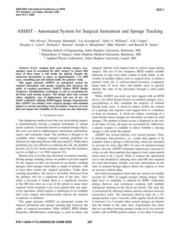
Basic Technical Information and ApplicationDefinitions and FunctionsThe name instrument transformer is a general classification appliedto current and voltage devices used to change currents andvoltages from one magnitude to another or to perform an isolatingfunction, that is, to isolate the utilization current or voltage from thesupply voltage for safety to both the operator and the end devicein use. Instrument transformers are designed specifically for usewith electrical equipment falling into the broad category of devicescommonly called instruments such as voltmeters, ammeters,wattmeters, watt-hour meters, protection relays, etc.Figure 1 shows some of the most basic uses for instrumenttransformers. Voltage transformers are most commonly usedto lower the high line voltages down to typically 120 volts on thesecondary to be connected to a voltmeter, watthour meter, orprotection relay. Similarly, current transformers take a high currentand reduce it to typically 5 amps on the secondary winding so that itcan be used with a watthour meter, ammeter, or protection relay.Figure 1 – Common uses of instrument transformersConstruction FeaturesPotential transformers consist of two separate windings on acommon magnetic steel core. One winding consists of fewer turns ofheavier wire on the steel core and is called the secondary winding.The other winding consists of a relatively large number of turns offine wire, wound on top of the secondary, and is called the primarywinding.Current transformers are constructed in various ways. One methodis quite similar to that of the potential transformer in that there aretwo separate windings on a magnetic steel core. But it differs in thatthe primary winding consists of a few turns of heavy wire capableof carrying the full load current while the secondary winding consistof many turns of smaller wire with a current carrying capacity ofbetween 5/20 amperes, dependent on the design. This is called thewound type due to its wound primary coil.Another very common type of construction is the so-called “window,”“through” or donut type current transformer in which the core hasan opening through which the conductor carrying the primary loadcurrent is passed. This primary conductor constitutes the primarywinding of the CT (one pass through the “window” represents a oneturn primary), and must be large enough in cross section to carrythe maximum current of the om3
Basic Technical Information and ApplicationConstruction Features - Indoor vs OutdoorAnother distinguishing feature is the difference between indoor andoutdoor construction. The performance characteristics of the twoconstructions are essentially the same, but the physical appearanceand hardware are different. The outdoor unit must be protectedfor possible contaminated environments while indoor units areprotected due to their being mounted in an enclosure of some kind.Thus most outdoor units will have larger spacing between line andground, which is achieved by the addition of skirts on the design.This provides larger surface creepage distances from the primaryterminals (at line potentials) to the secondary terminals and thebase plate (at ground potentials). For outdoor types the hardwaremust be of the non-corrosive type and the insulation must be ofthe non-arc-tracking type. One other feature that differentiates theindoor from the outdoor is the orientation of the primary terminals.The indoor types must be compatible for connection to bus typeelectrical construction as opposed to the outdoor types that arenormally on the pole-top installations.15kV Indoor CT15kV Outdoor CTHow To Modify The Ratio on a Current TransformerThe secondary consists of a larger number of turns of smaller wire.The number is dependent on the primary to secondary currenttransformation desired. If a lower current rating than is available isrequired due to a low load density, this can be achieved by loopingthe primary cable through the window of the CT. An examplewould be the need for a 100 ampere to 5 unit when the lowestcurrent rating made by the manufacturer was 200 to 5 amperes.By looping the cable through the window so that the cable passesthrough the window twice, we can make an effective 100:5 ampereunit out of a 200:5 ampere unit. Smaller increments of currentchange can be achieved by adding or backing off secondary turnsas well as primary turns, i.e., we can make a 110:5 ampere unit outof a standard 200:5 ampere unit by adding 2 primary turns andadding 4 secondary turns. The primary amperes turns must equal4the secondary ampere-turns. Thus 110 amperes X 2 turns is 220ampere turns on the primary. To equalize this on the secondary ofa standard 200:5 ampere unit which has 40 turns (40 X 5 amperes 200NI), we would have to add 4 secondary turns through thewindow of the CT thus giving us a total of 44 secondary turns X 5amperes 220 ampere turns. Thus we have modified a standard200:5 ampere CT to be a 110:5 ampere unit by adding 2 externalprimary turns and 4 external secondary turns to it. Had we chosento back off the 4 secondary turns instead of adding, we would havehad a 90:5 ampere CT. Refer to instruction for using a variable-ratiocurrent transformer.www.GEDigitalEnergy.com
Basic Technical Information and ApplicationMagnetic CircuitsInstrument transformers can be simplified with basic magneticcircuits. Figure 2 depicts the most basic magnetic circuit of an idealinstrument transformer. As a current passes through the primarywinding it induces a magnetic flux in the steel core. The flux flowsthrough the core and induces a current on the secondary windingproportional to the ratio of turns on the primary to the secondary.Instrument transformers are not a perfect device and incur lossesfrom resistance and stray inductance of the copper winding andcore. The two biggest losses are due to the copper windings thatcarry the current and the magnetic core that carries the flux. Figure3 below shows the electric circuit and associated losses of an actualtransformer. Figure 4 shows the equivalent circuit for a currenttransformer.Figure 2 – Basic Magnetic CircuitFigure 4 – Equivalent CircuitFigure 3 – Non-Ideal Magnetic CircuitRating and RatioThe rating of an instrument transfer is expressed by two groupsof numbers representing the nominal current or voltage whichmay be applied to its primary winding and the current or voltagewhich would then be induced in its secondary winding. Forexample, the designation 480:120 volt expresses the rating of thepotential transformer. This means that when 480 volts is appliedto the primary winding, 120 volts will be induced on the secondary.Likewise a designation of 400:5 amperes expresses the rating ofa current transformer and means that when 400 amperes flowthrough the primary, 5 amperes will flow through the secondary.volts and 115 volts as the secondary rating of PT’s having ratingsabove 24,000 volts. Similarly, industry standards have established5 amperes as the secondary rating of current transformers.The ratio of an instrument transformer is the relationship of itsprimary rating to its secondary rating. For example, the potentialtransformer mentioned above having a rating of 480:120 volts willhave a ratio of 4:1 and the current transformer having a rating of400:5 amperes will have a ratio of 80:1.Industry standards have established 120 volts as the secondaryrating of potential transformers having primary ratings up to 24,000www.GEDigitalEnergy.com5
Basic Technical Information and ApplicationCurrent Transformer Thermal Rating FactorRating factor (RF) is a term, which applies to a current transformer.In its application to a current transformer, it is the numberrepresenting the amount by which the primary load current maybe increased over its nameplate rating without exceeding theallowable temperature rise. In other words, it is a designation ofthe transformer’s overload capability. In order to be completelymeaningful, the ambient temperature at which the rating factorapplies should be stated. The standard ambient reference levelsare at 30 C or 55 C. In the manufacturer’s literature, a typicalstatement would be: RF 2.0 at 30 C ambient with RF 1.5 at 55 Cambient. These statements mean that in a 30 C ambient, the CTwill safely carry on a continuous basis 2 times the nameplate ratingand at 55 C ambient, it will carry 1.5 times the nameplate rating.The manufacturer states his 400:5 ampere CT has a rating factor of4.0 at a 30 C ambient and you wish to know how much you mustderate it when it is put in an enclosure where the highest ambienttemperature might be 55 C.The basic formula for a 55 C rise CT is:And for our particular example:It is very important that the ambient temperature be consideredwhen applying CT’s above the rating. Typical rating factors of CT’sare 1.0, 1.25, 1.33, 1.5, 2.0, 3.0, and 4.0.Many times the manufacturer will only list the CT rating factor at30 C ambient (room temperature). If you wish to know what therating factor is at some other ambient temperature, you will haveto convert the value by use of a rather simple proportional equation.Following is a typical example:Thus where the 400 ampere unit could carry (400 X 4.0) 1600 amperesprimary at 30 C ambient without exceeding the manufacturer’srecommended transformer thermal rating, it can safely carry only2.95 x 400 at 55 C. The IEEE standard C57.13 provides a graphdepicting the change in thermal rating to ambient temperature aswell.Potential Transformer Thermal RatingPotential transformers have a thermal rating rather than a ratingfactor as with the CT and it designates the maximum volt-ampereburden, which may be connected to its secondary at specifiedambient temperatures of either 30 or 55 C.Potential Transformer Overvoltage RequirementsThe IEEE standards allow two levels of operation. One is acontinuous operation level and one is for emergency conditions.A potential transformer must be capable of operating at 110%above rating voltage continuously provided the secondary burdenin volt amperes at this voltage does not exceed the thermal rating.The emergency rating of potential transformers is defined at oneminute of operation, thus enough time for protective equipmentto operate.Voltage Transformer Ratings and A4B5111L-GL-LL-GRVF1.25/8hr(25-161kV, 1.74/1min)(230-750kV, 1.40/1min)1.25/8hr1.40/1minIEEE C57.13-2008 defines five distinct groups of voltage transformersand provides ratings and characteristics of each grouping. Thistable summarizes each grouping.6www.GEDigitalEnergy.com
Basic Technical Information and ApplicationInsulation/Voltage ClassThe insulation class indicates the magnitude of voltage, which aninstrument transformer can safely withstand between its primaryand secondary winding and between its primary or secondarywinding and ground (core, case or tank) without a breakdown in theinsulation. Industry standards have established insulation classesranging from 600 volts up through 545 KV. System voltages presentlyextend up to 765 KV with 1100 and 1500 KV being investigatedfor future transmission expansions. Industry recommendationsare that the insulation class of an instrument transformer shouldbe at least equal to the maximum line-to-line voltage existing onthe system at the point of connection. For example, the insulationclass of a potential transformer used on a 7200/12470 volt systemshould be 15 KV even though the PT has a primary rating of 7200volts and is connected phase-to-ground. Similarly, any currenttransformer used on a 7200/12470Y volt system should be of the15 KV insulation class. Under fault conditions these units could besubjected to line-to-line voltage.PolarityIn the application of instrument transformers it is necessary tounderstand the meaning of polarity and to observe certain ruleswhen connecting watthour meters, relays, etc. If you will acceptthe fact, without proof, that the flow of current in the secondarywinding is in a direction opposite to in the primary winding, that is,180 out of phase with it, it will be relatively simple to understandthe meaning of polarity. At any instant, when the current is flowinginto one of the primary terminals it will be flowing out of one of thesecondary terminals.The polarity of a transformer therefore is simply an identification ofthe primary terminal and the secondary terminal, which satisfies thepreviously stated conditions. All instrument transformers, whethercurrent or potential will have polarity marks associated with at leastone primary terminal and one secondary terminal. These markingsusually appear as white dots or letter and number combinations.When number and letter combinations are used IEEE refers to H1 asthe primary terminal marking and to X1 for the secondary polaritymark.In applications which depend on the interaction of two currents,such as a watthour meter or protective relay, it is essential that thepolarity of both current and potential transformers be known andthat definite relationships are maintained.While all instrument transformers should be clearly marked as totheir polarity, it is sometimes necessary to verify existing markingsor to determine the polarity of an old or unmarked transformer. Onesimple method of determining polarity on a potential transformer isto connect a suitable DC permanent magnet voltmeter, preferablyone with a 150 volt range, across the high voltage terminals, withthe marked primary terminal of the transformer connected tothe plus ( ) terminal of the voltmeter. Then connect a batteryand connect the plus ( ) terminal of the battery to the markedsecondary terminal. Make an instantaneous contact betweenthe negative (-) terminal of the battery and the unmarked or (X2)secondary terminal of the transformer. A deflection or “kick” willbe indicated on the voltmeter. If the initial “kick” (the one resultingfrom making, not breaking the circuit) is in an upscale direction, thepotential terminals are marked correctly.Similarly, a polarity check may be made on a current transformer.Connect a DC permanent magnet ammeter of 5 ampere capacityor less (depending on the transformer ratio) across the currenttransformer secondary. Connect the plus connect a battery inseries and connect the negative (-) terminal of the battery tothe unmarked of (H2) marked terminal of the transformer, makean instantaneous contact between the marked or (H1) primaryterminal of the transformer and the plus ( ) terminal of the battery.If the initial kick (the one resulting from making not breaking thecircuit) is upscale, the current transformer terminals are markedcorrectly.Precautions should be taken when making this test on currenttransformers to prevent core magnetization from occurring dueto the direct current. Window or bar type units with low currentratings (400 ampere and down) are particularly susceptible tothis residual magnetism. It is a best practice to demagnetize theCT after using DC. This can be accomplished by connecting atleast 50 ohms variable across the secondary terminals and bringthe primary current up to full load. Reduce the series resistanceuntil it reaches zero without opening the secondary circuit. Forbest results, gradually reduce the primary circuit to zero beforedisconnecting the resistance circuit.www.GEDigitalEnergy.com7
Basic Technical Information and ApplicationAccuracy Classification and BurdenThe IEEE has established standardized methods of classifyinginstrument transformers as to accuracy and burden. An accuracyclassification for an instrument transformer includes the standardburden as well as the maximum percent error limits for line powerfactors between 100% and 60% lagging. A typical CT classificationmight be 0.3 B0.5 where the 0.3 is the percent allowable error andthe B0.5 is the secondary burden in ohms impedance. The accuracyis dependent on the burden.A utility is trying to determine what accuracy and burdenclassification CT to purchase for a particular metering application.The various meters and instruments to be used are known and thedistance and size of wire to be used between the CT and the metersare knownStandard ANSI values of accuracy burdens for CT’s and PT’s arelisted below, as well as in the IEEE standards manual, C57.13.It is extremely important at this point to have a very clearunderstanding of the term “burden” as it is used in connection withinstrument transformer accuracy classifications. The term “burden”has been adopted to distinguish it from “load” which is generallyassociated with the primary, especially with current transformers.For example, the load rating of a current transformer indicatesthe load (in current) which may be applied to its primary, whilethe burden rating indicates the amount of resistance (in ohms)and inductance (in milli-henries) which may be connected to itssecondary without causing a metering error greater than specifiedby its accuracy classification.The types of meters and relays and the size and length of wireconnected to the secondary side of the instrument transformermake up its burden.These values can be calculated by converting each device intoterms of voltamperes and power factor, and doing a vector analysisto determine what the total effective burden on the transformer is.A more practical way is to obtain from the manufacturer the burdenof each device in terms of watts and vars and calculate the totalthe total effective burden on the instrument transformer. A typicalexample might be as follow:8CONCLUSION: Since 6.94 VA at .95 P.F. exceed B0.2 burden (which is5.0 VA at .9 P.F.) the utility must use a transformer that has a 0.3B0.5classification (or 12.5 VA at .9 P.F. capability).www.GEDigitalEnergy.com
Basic Technical Information and ApplicationMetering AccuracyThere are two sources of error in instrument transformers, namelyratio error and phase angle error. In a given transformer, themetering error is the combination of the two separate errors. Thiscombination is called Transformer Correction Factor (TCF), IEEEhas established accuracy classes for both current and potentialtransformers. The limit of permissible error in a potential transformerfor a given accuracy class remains constant over a range of voltagefrom 10% below to 10% above rated voltage. In the figure to theright is a standard test card provided by the manufacturer showingthe performance of the CT at 10% and 100% of rated current.The limit of permissible error in a current transformer accuracy classhas one value at 100% rated current and allows twice that amountof error at 10% rated current. Typically 0.3% error is acceptable forwatthour metering, 0.6% to 1.2% error for indicating instruments.The figure to the right shows the performance limits of a standardmetering 0.3% accuracy CT with a rating factor of 4.0.High Accuracy Instrument TransformersTwo new accuracy classes have been developed by IEEE C57.13.6 toaccommodate the shift towards electronic relays and meters fromthe traditional induction devices. Consequently, manufacturershave begun to improve accuracy of instrument transformers to takeadvantage of the lower impedance of the devices. Included in thenew high accuracy standard are new testing points and burdens toverify performance. New burdens of E.04, (1.0 Volt-Ampere at 5Amp,unity power factor), E0.2, (5.0 Volt-Ampere at 5Amp, unity powerfactor), and low current test point of 5% versus the traditional 10%rated current, are now required.0.15 Accuracy Instrument TransformersCurrent transformers must maintain 0.15% accuracy from ratedcurrent through rating factor at rated burden. At 5% ratedcurrent through 100%, the current transformer must maintain0.3% accuracy. No accuracy is guaranteed at levels below 5%.Voltage transformers are 0.15% accuracy from 90%-110% of ratedvoltage.The associated figure depicts the performance with accuracy on thevertical axis and rating factor on the horizontal axis.0.15S Accuracy Instrument TransformersCurrent transformers must maintain 0.15% accuracy from 5%rated current through rating factor at rated burden. No accuracyis guaranteed at levels below 5%. Voltage transformers are 0.15%accuracy from 90%-110% of rated voltage.Relay Accuracy of a Current TransformerCurrent transformers that are used to operate relays for control andsystem protection must have certain accuracy during over-currentconditions. The transformer must be able to not only withstand thehigh currents involved, but must also transform current to a lowervalue suitable for application to the relay terminals, and do thiswith a reasonable accuracy. A typical relay accuracy classificationmight be C200 or T200.The “C” stands for calculated and means that the window and bartype units which have a fully distributed secondary winding on alow leakage flux core thus leading itself to calculated values. The“T” stands for tested because wound type units do not have fullydistributed windings, they must be tested because the leakagereactance is not predictable. The last number is the secondaryvoltage that can be developed at the secondary terminals withoutsaturation.www.GEDigitalEnergy.com9
Basic Technical Information and ApplicationThus the meaning of the relay classification!C200 would be (10% accuracy inferred at 20 X normal current Xsecondary impedanceORV IR200 volt (20 X 5 amps) X B2.0 ohmsThus, this CT would have an error of no larger than 10% at 20 timesnormal secondary current with a secondary burden of 2.0 ohms.Manufacturers will often offer a graph of the excitation performanceof a particular CT. The graph allows the end user to determine theperformance of the CT over the entire range of secondary currentand ensure that the CT will function as required. The figure to theright shows a typical excitation curve of a relay class CT.Connections - Potential TransformersPotential transformers are normally connected across two lines ofthe circuit in which the voltage is to be measured. Normally theywill be connected L-L (line-to-line) or L-G (line-to-ground). A typicalconnection is as follows:When a phase relationship of “direction of flow” is of no consequence,such as in a voltmeter which operates only according to themagnitude of the voltage, there is no need to observe the polarity ofthe transformer. However, in watthour meter applications, polaritymust always be observed.Most potential transformers have a single winding secondary aspreviously shown, however, they may have tapped secondarywindings, or dual secondary windings.Connections - Current TransformersCT’s with wound primaries always have their primary windingsconnected in series with the line and the load and their secondarywindings connected to the burden (the watthour meter current coil)as show below:it is necessary to have available two ratios of primary to secondarycurrent from the same secondary winding of the CT. This may beaccomplished by adding a tap in the secondary winding to geta second ratio. The ratio obtained by the tap is usually one-halfthe ratio obtained by the full secondary winding. A schematicexample is shown below. With 200 amperes flowing in the primary,Current transformers having a center tapped secondary arereferred to as a dual ratio CT. They are used in applications where10www.GEDigitalEnergy.com
Basic Technical Information and Applicationa connection X2 – X3 will produce 5 amperes out of the secondary.Then as the load grows to 400 amperes, the secondary circuit willbe reconnected to X1 – X3 to produce 5 amperes in the secondary.It is not recommended to reconnect while the unit is energized, thesecondary terminals must be short circuited so as not to inducehigh voltage in the secondary circuit when the circuit is opened tomake the connection. Voltage from a few hundred volts to severalthousand volts, dependent on the design, can be developed in thesecondary circuit when it is open circuited with current flowingin the primary winding. On a dual ratio tapped secondary CT,both the full winding and the tapped winding cannot be operatedsimultaneously. The unused terminal must be left open to avoidshort circuiting a portion of the secondary winding.A schematic of this would like this:In this design, if both the circuits are not going to be usedsimultaneously, then the unused circuit must be short circuitedwhile the other is energized or you will develop an induced highvoltage on the open circuited unused CT.Another design of CT quite commonly used is the double secondaryCT. In this configuration the CT has two cores, two secondarywindings and one common primary winding. Its application wouldbe for using one CT to both meter and relay a common circuit wherethe metering circuit must be isolated from the relaying circuit.Connections - Standard MeteringTypical current transformer connections on three common circuitswill illustrate the principles involved in making CT installations.THE 4 WIRE, “Y’ 3 PHASE CIRCUITTHE 4 WIRE, 3 PHASE CIRCUIT(DELTA CONNECTION)www.GEDigitalEnergy.com11
Basic Technical Information and ApplicationTypical Examples:g12GE Digital Energy - ITI1907 Calumet StreetClearwater, Florida, USA, 33765www.GEDigitalEnergy.comDigital EnergyITIwww.GEDigitalEnergy.com
The ratio of an instrument transformer is the relationship of its primary rating to its secondary rating. For example, the potential transformer mentioned above having a rating of 480:120 volts will have a ratio of 4:1 and the current transformer having a rating of 400:5 amperes will