Transcription
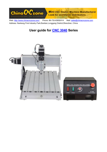
Web: http://www.chinacnczone.com/ Phone: 86-755-83692414 Mail: sales@chinacnczone.comAddress: Nankeng First Industry Park,Bantian,Longgang District,Shenzhen, ChinaUser guide for CNC 3040 Series
CONTENTMain features forthis mini CNC router machine CNC 3040Z-DQ V2 . - 2 How to use CNC 3040Z-DQV2 . - 4 1. Software . - 4 2. How to set the software: . - 10 3. Try to use your CNC . - 17 4. To know the engraving bits in common use . - 27 --1-
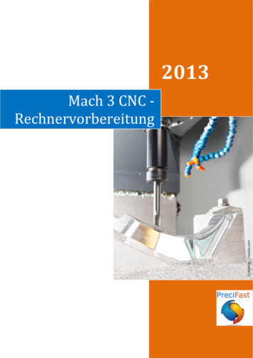
Main features for this mini CNC router machine CNC 3040Z-DQ V2Ball Screw4 Axis230W DC spindleLimited switch addedAuto checking function added-2-
Notice:1. This machine should be used with the PC parallel port and controlled by Mach 3 or other software.The PC parallel port should work in condition of the EPP mode, the setup of the EPP mode should beapplied on the main board BIOS.2. You’d better use the PC to control the machine, especially for this machine and do not install othersoftware if conditions permit. And please do not use the Laptop to control the machine, the battery of somelaptops will impact the pulse signal of the machine and the voltage of some parallel port is very low, it willcause the lost of the signal.Warn:You should setup the software correctly; it will make the machine works well. If you do not do it welland try to run the machine, it may damage the machine or cause the danger.When you install or setup the machine, please do not turn on the control box, it may cause somedamages.Please do not put the connectors on the control box, when it is poweron. You should regulate thespindle as the low speed when you want to restart it. The interval of the open/close button time should be atleast 30s, when you restart the spindle or turn on the control box again, otherwise it will cause the damagesof the control box.Our machine is 220V or 110V, when it is power on, please do not open the control box, do not touchthe wiring connectors and not touch the running cutters, please wear the glasses or mask to protectyourself.Main technical details forCNC 3040Z-DQ V2 are as below:CNC 3040Z-DQ V2 technical detailesX,Y,Z Working Area:275 385 55mmMax. Feeding height: 70mmOutside dimension610 480 400mmTable size530 320mmLathe structure6061/6063 Aluminium alloyStepping motortwo-phase 57/1.8ADrive unit:1204 Ball ScrewSliding unit::Chromeplate shaftMaximum speed:0-4000mm/minEngraving speed:300-2500mm/minRepeat positioningAccuracy:0.05mmSpindle motor:spindle motor with direct current(200w)Spindle speed:1000 8000RPM/MINCutting tool-holder:ER11/3.175mmInterface:Parallel portSoftware Compatability:Mach3/Emc2,(Type3,Wentai, ArtCAM)Command code:G code/.nc/.ncc/.tab/.txt-3-
Machine weight:28kg(including packaging)Outside packing62x58x48CMHow to use CNC 3040Z-DQ1. Software1. Open the Mach 3 file; double click the “Mach3xxxxx.Exe”to start.2. Click the “Next”-4-
3. Click the “Yes”4. Click the “Next”-5-
5. Click the “Next”-6-
6. Click the “Next”7. Click the “Ok”8. Click the” Finish”-7-
9. Click the“Ok”-8-
10. Click the“Ok”After installing the Mach 3, on the desktop, there will occur 3 icon as follows:Notice: do not open them, please restart your PC at first (if you open the software not restart PC,itneed uninstall fully and reinstall it)After restarting the PC, please double click the “MACH 3 MILL” icon, then you can enter the setup ofthe software (you can delete the other two icons Mach3 and Mach3Turn)Open the G code---all the axis should be“0”---then start to engrave, You can choose the “Feed hold” topause the working when it has something, if something emergency happens, you can use the “Reset” oryou can adjust the “Feed rate”.-9-
2. How to set the software:1. After restarting the PC, choose the MACH 3 MILL icon on the desktop to start the Mach 3.2. Open the “Config-- selects Native Units” menu, and then choose the “MM’s”- 10 -
3. See as below,open”Config--Ports and Pins” to enter the setup.4. To check whether all the data is same as the follows in the big red circle and then choose OK tocontinue.- 11 -
5. Click “Motor Outputs” to setup the Pin of the stepper motor as followThis part is very important; please check your setup is as same as the data above. Even a smallerror will cause the machine working incorrectly. Do not forget to save the setup.Remark:(1). If you want to use the 4th axis (A axis), you can setup the A axis data as follows:(2).”Dir Low Active” This choice is to set up the Direction of the motor, if you find the runningdirection of the axis is inverse, you can choose the “Dir Low Active” to change the direction andthen save the setup. As below picture:- 12 -
6. The clients who bought the Control box from us, need to setup the E-stop signal, still in “Ports andPins” menu to click “Input Signals” to find the “Estop”,then setup as follow, final apply and thensave.( Emergency setting )- 13 -
7. Limited Switch setting in “Ports and Pins” menu to click “Input Signals” and set X, Y, Z as below:8. Output signals setting in “Ports and Pins” menu to click “Output Signals”, set as below, and then save.- 14 -
9. Spindle setup in “Ports and Pins” menu to click “Spindle Setup”, set as below, and then save.10. The setup of the Stepper motor: Config-- Motor Tuning--- X Axis---setup the X axis asfollows---then“SAVEAXIS SETTINS”, then s etup the Y axis and Z axis,final click “OK”.X Axis, Y Axis, ZAxis parameters should the same.\- 15 -
The setup is over, Please close the Mach software that all data setup can be available. And then open itagain to check whether all the data is correct otherwise can’t run your machine well.- 16 -
3. Try to use your CNC1. First let us to learn this machine, below take 3020 for example, The full kit has the machine(theFrame), the electrical control box, X,Y,Z stepper motors, the spindle and the spare parts box(it contains the4 pcs presser feet, 5 pcs test bits, 1 pair of spare carbon brush, 1 pcs fuse pipe,ancethe spanner of thespindle, the 6 hexagonal spanner and the nuts and screws).- 17 -
(1) Our machine is made of the aluminum alloy, if you drop it from the top on the floor or hard hit, it willdamage the machine. Please put this machine on the stable desk, the thin desk may cause moreresonance when it is running.(2) In the electrical control box, there are the switching power supply, stepper driver board, the spindlespeed regulator, please put it in a ventilating condition and around it, there should not have theelectromagnetic interference within 10 meters.(3) Please sort out the power cables and connecting cables, do not put it in a mess, maybe it willobstruct the working of the machine. Please remain some excess of the cable for the gantry and the X axis.(4) Please try to study yourself and test it, If you have some questions, you can ask us or discuss it onthe CNC Forum2. The wiring and yourself-checking(1) Wiring:Put the cables into the corresponding port, on the connectors there print the X, Y, Z, the cable of thespindle has no mark, but it is a two-wire plug. On the electrical control box, it prints the marks of the ports.The LIMIT-IN is the spare port for the 4th axis or external limit switch or E-stop etc.Now just connect the X, Y, Z stepper motor cables and the spindle cable, but the parallel cables do notconnect it at first.Please make sure that all the connectors are tight to avoid the loose contact.- 18 -
2. Yourself-checkingThe aim of the checking is to make sure that the electrical control box and the machine are well wiredand all axes can be controlled.At first, power off the spindle and the driver power, “o” is off, “l” is on, and regulates the spindle in thissafe position (see the photo below). The E-stop switch is off.Then wrest the X axis screw by hand to feel it (at this time you can move it easily), and then connectthe power of electrical control box and open the driver switch, at the time, you can hear a small voice of themoving of the X, Y, Z stepper motors. Now try to move the X axis screw to check whether you can move iteasily by hand, if it does not move, it means this axis have been controlled by the control box, after this,please try to move the Y, Z axis screw(move the coupling is ok), if they cannot be moved, it means all axisare self-locked and fine.- 19 -
If anyone screw can be moved, please check the wiring of this axis to see whether it is well connected, ifthe 3 axis all can be moved, please contact us. if 3 axis are ok please continue.Then please power off the driver and make sure the spindle is in the safe position. Power on thespindle and adjust clockwise slowly of the spindle speed regulator to the first dot, the spindle motor willstart to move, continue to adjust clockwise, spindle will run more and more quickly.Remark: If you face the spindle, the clockwise direction is the right direction. If you find the direction isanticlockwise, please power off the spindle and exchange the two connectors will be fine.- 20 -
Notice:(1).When the spindle is power-on, the voltage between the two connectors of the spindle is 90VDC,when the spindle is running, please do not touch the cutters and wear the glasses and mask.Please keep the children away from the machine.(2) Before powering on the spindle, please make sure the spindle speed regulator is in the safeposition and then power on the spindle and speed up slowly. When power off the spindle, you canturn off the spindle power supply switch directly and regulate the speed regulator to the safeposition. If the speed regulator is in the high-speed position, it will cause the brunt of the fuse andover current, this will do damage to the speed regulating board in the control box.3.Test by PC(1)In the power off, use the parallel cable to connect the control box and the PC parallel port.(2) Start the PC, open the “MACH 3 mill “and the drive power, and make sure the 3 axis are self-lockedautomatically. Check the Mach 3 interface, the E-stop button is twinkling, if so, click it to stop it (if you click it,and the E-stop button on the interface is still twining, please check the E-stop button on the control box ispressed, if it is pressed, please move it clockwise to make it unpressed,if the driver is power off the E-stopbutton is twinkling and can’t stop).(3)After stopping twinkling E-stop on MACH 3 interface, you can type the direction key of the PCkeyboard, to check whether the X, Y, Z axis can move.If it cannot move: A-check the X, Y, Z data on the Mach 3 is changed or not when typing the directionkey on the keyboard, if the data changes but the X, Y, Z axis do not move, pleasefollow the step as below:B-check the setup of the pin.C-check the connection of parallel cableD-check the manual control button “JOG ON/OFF”whether is green. Refer the imagebelowE-contact us- 21 -
If all the axis can move, please check the direction of the axis coordinate is right (see below).If you find the axis which move wrong direction please changes the setup as Page10 green letters?- 22 -
PS: you can use the keyboard to control the direction of the axis, and also you can use the manual controlkeyboard of Mach 3 by using the mouse to control the movement of the X, Y, Z axis.Press the “TAB“key on the keyboard then it will pop-up the MACH manual control interface as the figurebelow.Now the test of the Mach 3 communication with the machine is over. If it still can not realized the manualcontrol, please do as follows:(1)Uninstall the Mach3 and use other versions of the Mach 3 to test(because some parallel port is notcompatible with MACH software)(2)Check the PC parallel port is fine or change another PC to test it.(3)If the machine’ X, Y, Z axis can be self-locked, you should think about the compatibility of the PCand the Software.(4)You must restart the PC when finish installing of the MACH 3.4. Engraving test- 23 -
We use a Chinese character”雕” to test the machine.First: Assembly the materials(1)Find a soft material about 12CM*12CM, like PVC. WOOD, PMMA or other plastic material(2)Fix the board on the working table as below, notice the screw and nuts should be tight but do notmake the T slotted board out of shape.Second: Cutter trace unload running test without the cutter(1)Copy the document you want to engrave to the desktop of your PC, and then open the Mach 3Mill---start the G code and import the document you want to engrave, also you can use the Machmenu---file---load G code to import it.- 24 -
(2)Import the G code of”雕”, then it will display on the PC as below(3)Power on the control box driver, move the spindle tool bit to the left-bottom of the material board bymanual control the three axis, the area in the red circle (the image below)is the safe area. The leftbottom red-green WCS arrowhead above is the original point, move the spindle bit (without cutter) tothis point.(4)Put the Z axis a little higher to avoid to touching the clamping nuts. Clear all the axis to zero and clickthe Green (ALT-R) button to start. At the same time, please pay attention to the windows of thesoftware, the moving dashed is the trace of the machine. If you find the trace is incorrect, please poweroff the drive and check the unit of the Mach 3 weather is “MM” and axis WCS.(5)This test engraving dimension is 7*7*CM, 1MM thickness, engrave it twice, each time the depth is- 25 -
0.5MM, so it will work twice the same trace, when it idle running, please check whether it will touch theclamping board, if so, please recheck the original point of the engraving, Otherwise it will damage thecutter, the material even the machine.Notice: when doing holed-
Software Compatability: Mach3/Emc2,(Type3,Wentai, ArtCAM) Command code: G code/.nc/.ncc/.tab/.txt - 4 - Machine weight: 28kg(including packaging) Outside packing 62x58x48CM How to use CNC 3040Z-DQ 1. Software 1. Open the Mach 3 file; double click the “Mach3xxxxx.Exe”to start. 2. Click the “Next” - 5 - 3. Click the “Yes” 4. Click the “Next” - 6 - 5. Click the “Next