Transcription
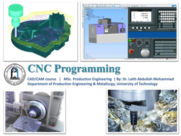
CNC ProgrammingCAD/CAM course MSc. Production Engineering By: Dr. Laith Abdullah MohammedDepartment of Production Engineering & Metallurgy, University of Technology
Manual [Write code directly] Computer-assisted [Draw cutter path] CAD/CAM [ Draw the part, Cutter path is generated]o Offline programming linked to CAD programs.o Conversational programming by the operator.o MDI Manual Data Input.o Word-Address Coding using standard G-codes and M-codes.Basics of NC Part Programming:During secondary motion either the tool motion, moves relative to the workpiece or theworkpiece moves relative to the tool.In NC programming, it is always assumed that the tool moves relative to the workpiece nomatter what the real situation is.The position of the tool is described by using a Cartesian coordinate system. If (0,0,0)position can be described by the operator, then it is called floating zero.Structure of an NC Part Program:Commands are input into the controller in units called blocks or statements.Block Format:1. Fixed sequential format2. Tab sequential format3. Word address format
Example: Assume that a drilling operation is to be programmed as:1. The tool is positioned at (25.4,12.5,0) by a rapid movement.2. The tool is then advanced -10 mm in the z direction at a feed rate of 500 mm/min., with theflood coolant on3.The tool is then retracted back 10 mm at the rapid feed rate, and the coolant is turned off.Word address formatN50 G00 X25400 Y125 Z0 F0N60 G01 Z-10000 F500 M08N70 G00 Z0 M09INFORMATION NEEDED by a CNC1. Preparatory Information: units, incremental or absolute positioning2. Coordinates: X,Y,Z, RX,RY,RZ3. Machining Parameters: Feed rate and spindle speed4. Coolant Control: On/Off, Flood, Mist5. Tool Control: Tool and tool parameters6. Cycle Functions: Type of action required7. Miscellaneous Control: Spindle on/off, direction of rotation stops for part movementrotation,This information is conveyed to the machine through a set of instructions arranged in a desiredsequence – Program.
BLOCK FORMATSample BlockN135 G01 X1.0 Y1.0 Z0.125 F5Restrictions on CNC blocks Each may contain only one tool move Each may contain any number of non-tool move Gcodes Each may contain only one feedrate Each may contain only one specified tool or spindle speed The block numbers should be sequential Both the program start flag and the program number must be independent of all othercommands (on separate lines) The data within a block should follow the sequence shown in the above sample blockExample CNC ProgramN5 G90 G20N10 M06 T3N15 M03 S1250N20 G00 X1 Y1N25 Z0.1N30 G01 Z-0.125 F5N35 X3 Y2 F10N40 G00 Z1N45 X0 Y0N50 M05N55 M30Each instruction to the machine consists of a letter followed by anumber.Each letter is associated with a specific type of action or piece ofinformation needed by the machine.Letters used in CodesN,G,X,Y,Z,I,J,K,F,S,T,M
Table of Important G codesG00 Rapid TransverseG01 Linear InterpolationG02 Circular Interpolation, CWG03 Circular Interpolation, CCWG17 XY Plane,G18 XZ Plane,G19 YZ PlaneG20/G70 Inch unitsG21/G71 Metric UnitsG40 Cutter compensation cancelG41 Cutter compensation leftG42 Cutter compensation rightG43 Tool length compensation (plus)G43 Tool length compensation (plus)G44 Tool length compensation (minus)G49 Tool length compensation cancelG80 Cancel canned cyclesG81 Drilling cycleG82 Counter boring cycleG83 Deep hole drilling cycleG90 Absolute positioningG91 Incremental positioning
Table of Important M codes M00 Program stopM01 Optional program stopM02 Program endM03 Spindle on clockwiseM04 Spindle on counterclockwiseM05 Spindle stopM06 Tool changeM08 Coolant onM09 Coolant offM10 Clamps onM11 Clamps offM30 Program stop, reset to start
N CodesGives an identifying number for each block of information.It is generally good practice to increment each block number by 5 or 10 to allow additionalblocks to be inserted if future changes are required.X,Y, and Z CodesX, Y, and Z codes are used to specify the coordinate axis.Number following the code defines the coordinate at the end of the move relative to anincremental or absolute reference point.I,J, and K CodesI, J, and K codes are used to specify the coordinate axis when defining the center of a circle.Number following the code defines the respective coordinate for the center of the circle.F-code: used to specify the feed rateS-code: used to specify the spindle speedT-code: used to specify the tool identification number associated with the tool to be used insubsequent operations.
Part program: A computer program to specify. Which tool should be loaded on the machine spindle; What are the cutting conditions (speed, feed, coolant ON/OFF etc) The start point and end point of a motion segment How to move the tool with respect to the machine.Standard Part programming language: RS 274-D (Gerber, GN-code)The RS274-D is a word address formatEach line of program 1 blockEach block is composed of several instructions, or (words)Sequence and format of words:N3 G2 X 1.4 Y 1.4sequence noZ 1.4destination coordinatespreparatory functionI1.4J1.4 K1.4dist to center of circleF3.2S4 T4 M2toolfeed rate spindle speedmiscellaneous function
Manual Part Programming ExampleWrite a G-code program for the part shown belowN010 G70 G90 G94 G97 M04N020 G17 G75 F6.0 S300 T1001 M08N030 G01 X3.875 Y3.698N040 G01 X3.875 Y9.125N050 G01 X5.634 Y9.125N060 G03 X7.366 Y9.125 I6.5 J9.0N070 G01 X9.302N080 G01 X3.875 Y3.698N090 G01 X2.0 Y2.0 M30N100 M00
5”2.5”p3p2p4p51”Tool size 0.25 inch,Feed rate 6 inch per minute,Cutting speed 300 rpm,Tool start position: 2.0, 2.0Programming in inches5”45 (4, 4)p1p0 (2, 2)Motion of tool:p0 p1 p2 p3 p4 p5 p1 p0
1. Set up the programming parameters5”2.5”p3p2p4p51”Programming in inches5”Use absolute coordinatesFeed in ipm45 N010 G70 G90 G94 G97 M04(4, 4)p1p0 (2, 2)Spindle speed in rpmSpindle CCW
2. Set up the machining conditions5”2.5”p3p2p4p51”Machine moves in XY-planeUse full-circle interpolation5”Feed rateSpindle speed45 N020 G17 G75 F6.0 S300 T1001 M08(4, 4)p1p0 (2, 2)Tool no.Flood coolant ON
3. Move tool from p0 to p1 in straight line5”2.5”p3p21”p4p5Linear interpolationtarget coordinatesN030 G01 X3.875 Y3.6985”45 (4, 4)p1p0 (2, 2)
4. Cut profile from p1 to p25”2.5”p3p2p4p51”Linear interpolation5”target coordinatesN040 G01 X3.875 Y9.12545 or(4, 4)p1p0 (2, 2)N040 G01 Y9.125X-coordinate does not change no need to program it
5. Cut profile from p2 to p35”2.5”p3p2p4p5Linear interpolationtarget coordinates1”N050 G01 X5.634 Y9.1255”y 9 0.125 9.125(6.5 - x)2 0.1252 (1 - 0.125)2x 5.63445 p3(x, y)(4, 4)p1(6.5, 9).125p0 (2, 2)1”
6. Cut along circle from p3 to p45”2.5”p3p2p4p51”circular interpolation, CCW motion5”target coordinates45 (4, 4)p1p0 (2, 2)N060 G03 X7.366 Y9.125 I6.5 J9.0coordinates of center of circle
7. Cut from p4 to p55”2.5”p3p2p4p51”5”Linear interpolation45 (4, 4)p1p0 (2, 2)target coordinates (Y is unchanged)N070 G01 X9.302
8. Cut from p5 to p15”2.5”p3p2p4p51”5”Linear interpolationtarget coordinates (see step 3)45 N080 G01 X3.875 Y3.698(4, 4)p1p0 (2, 2)
9. Return to home position, stop program5”2.5”p3p2p4p51”Linear interpolationtarget coordinates (see step 3)5”N090 G01 X2.0 Y2.0 M3045 (4, 4)p1p0 (2, 2)end of dataN100 M00program stop
CNC Programming Example [2]Cylindrical Part
N0005 G53N0010 T0404To cancel any previous working zero pointN0010 Sequence numberT0404 Select tool number 404N0020 G57 G00 X26.0 Z0.0 S500 M04G57 To set the working zero point as savedG00 Rapid movement (no cutting)X26.0 X location (as a diameter; 13 form zero)Z0.0 Z locationS500 Spindle speed is 500 rpmM04 Rotate spindle counterclockwiseN0030 G01 X-0.20 F100G01 Linear interpolation (cutting)X-0.20 Move only in x direction until you passthe center by 0.1 mm (facing)F100 Set feed rate to 100 mm/min.N0040 G00 Z2.0G00 Move rapidly away from work piece (no cutting)Z2.0 the movement is 2 mm away from the face.N0050 X50.0 Z50.0Go to a safe location away from the workpiece [x 50(25 from zero), z 50] to change the tool.N0060 T0404T0404 Select tool number 404
N0070 G57 G00 X22.50 Z2.0 S500G57 PS0G00 Rapid movement (no cutting)X22.50 X location (as a diameter; 11.25 form zero)Z2.0 Z locationS500 Spindle speed is 500 rpmN0080 G01 Z-30.0 F100G01 Linear interpolation (cutting)Z-30 Move only in z direction (external turning)F100 Set feed rate to 100 mm/min.N0090 G00 X23.0 Z2.0 S500G00 Move rapidly away from work piece (no cutting) to location x 23.0(11.50 from zero) and z 2.0.N0100 G84 X17.5 Z-20.0 D0 200 D2 200 D3 650G84 Turning cycle for machining the stepX17.5 final diameterZ-20 length of step is 20 mmD0 200 Finish allowance in X direction (0.2mm) D2 200 Finish allowance in Z direction(0.2 mm)D3 650 Depth of cut in each pass (0.65 mm)N0110 G00 Z2.0G00 Move rapidly away from workpiece (no cutting)Z2.0 the movement is 2 mm away from the face.N0120 X50.0 Z50.0X50.0 Z50.0 Move to the tool changing locationN0130 M30M30 Program End
CNC Programming Example [3]Row MaterialFinished Part
Flow of Computer-Aided CNC Processing Develop or obtain the 3D geometric model of the part, using CAD. Decide which machining operations and cutter-path directions are required (computerassisted). Choose the tooling required (computer assisted). Run CAM software to generate the CNC part program. Verify and edit program. Download the part program to the appropriate machine. Verify the program on the actual machine and edit if necessary. Run the program and produce the part.
Exercise CNC Milling Programming: Contact plateThe contact plate on the drawing is to be produced on a CNC vertical milling machine from ablank of AlMg1 dimensioned 100 x 100 x 25 mm. Prepare, test and correct the manufacturingprocess with the MasterCAM CNC Milling Simulator. Define the workpart zero, work out theprocess layout, set-up form and NC program.
Exercise CNC Turning Programming: Drill sleeveThe drill sleeve is to be produced on a CNC lathe as to the drawing from a blank made of AlMg1dimensioned 90 x 128 mm. The manufacturing process is to be prepared with the MasterCAMCNC Simulator including all planning documentation. Use the compound fixed cycle G71. Test,correct and print the NC program.
Manual Part Programming Example Write a G-code program for the part shown below N010 G70 G90 G94 G97 M04 N020 G17 G75 F6.0 S300 T1001 M08 N030 G01 X3.875 Y3.698 N040 G01 X3.875 Y9.125 N050 G01 X5.634 Y9.125 N060 G03 X7.366 Y9.125 I6.5 J9.0 N070 G01 X9.302 N080 G01 X3.875 Y3.698 N090 G01 X2.0 Y2.0 M30 N100 M00. Tool size 0.25 inch, Feed rate 6 inch per minute, File Size: 1MBPage Count: 28Explore furtherCNC Programming PDFs [Easy Download and Print .www.cnccookbook.comBasic G and M codes - FITstaff.fit.ac.cyCOMPUTER NUMERICAL CONTROL PROGRAMMING BASICSwww.engr.uvic.caFundamentals of CNC Machining - Texas A&M Universityhaastech.tamu.edu[PDF] CNC Programming Handbook By Peter Smid Free Download .learnengineering.inRecommended to you based on what's popular Feedback