Transcription
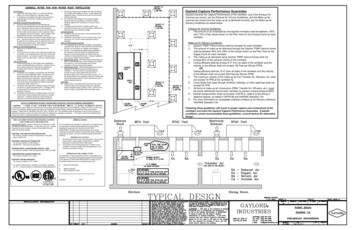
ELECTRICAL1. Locate Fan Start/Stop Switch in a convenient location.Refer to the wiring diagram for required voltage.2. If ventilators are equipped with light fixtures, provide aseparate light circuit to the ventilator as shown onelectrical plan.EXHAUST VOLUME REQUIREMENTS3. Exhaust Volumes as shown on the drawings aredetermined by established Gaylord engineering methodsand in accordance with the terms of the ventilator'slisting. These air volume levels require that the make-upair be brought into the space in such a way that it doesnot negatively affect the ventilator. See the Make-up AirRequirements and the "Typical Design" drawing.4. Ventilator static pressure is noted on each ventilator planview. Total duct system and other external static's mustbe added to the ventilator static for determining the totalsystem static pressure drop. Static based on operationat mean sea level at 75 F kitchen ambient.MAKE-UP AIR REQUIREMENTS5. Make-up air is critical to the performance of theventilator.6. The total amount of make-up air (supply air) brought intothe kitchen must be between 90% and 100% of the totalexhaust volume. It should be brought in throughout thekitchen evenly for best results. See the "Typical Design"drawing.AIR FLOW RATES7. Exhaust and Supply Air Flow Rates were establishedunder controlled laboratory conditions. Greater Exhaustand/or lesser Supply Air Flows may be required forcomplete vapor removal in specific installations.INSTALLATION8. Ventilators to be installed in accordance with NFPA-96and all other local applicable codes. Contractors mustreview applicable codes with code authorities beforeapproving drawings for fabrication. Special attentionmust be given to code regulations relative to clearancesfrom surrounding combustible and limited combustibleconstruction (walls, ceiling, etc.).9. Ventilators manufactured in multiple sections are factorypre-wired to a single connection point. Ventilator wiringis disconnected for shipment to be reconnected byelectrical contractor.10. Ventilators manufactured in multiple sections may havedrains factory interconnected (see drawing) to a singleoutlet point. Ventilator plumbing is disconnected forshipment to be reconnected by plumbing contractor.11. All ductwork beyond the ventilator duct take-off collar tobe provided and installed by others, in accordance withapplicable codes. Exhaust ducts must be continuouslywelded liquid tight.12. All ventilators are equipped with hanging brackets.Hanging rods to be supplied by ventilator installer.Hanging weight of the ventilator(s) is noted on eachdrawing.13. Ventilators manufactured in multiple sections areprovided with bolts, clips, and all necessary hardware forreconnecting by the ventilator installer.CONSTRUCTION14. Ventilators are manufactured in strict accordance withGaylord specifications.15. Ventilators constructed of 18 Ga. stainless steel, Type300 series, No. 4 finish unless otherwise noted ondrawings.FIRE EXTINGUISHING SYSTEM16. Fire extinguishing system to be installed in accordancewith NFPA-96. Refer to "FIRE PROTECTION SYSTEMNOTES" for information on supplier and installation.17. Caution: Fire extinguishing system piping installed onthe ventilator at job site should be coordinated withGaylord to ensure piping does not interfere with theventilator's operation/performance. Improper installationmay void the Listings of the ventilator.18. IMPORTANT NOTE: NFPA-96 requires that all gas andelectric cooking equipment, that is protected by surfacefire protection, must automatically shut off uponactivation of the fire extinguishing system.19. IMPORTANT NOTE: Most building departments requireseparate hood and fire protection permits prior toinstallation. The hood permit is typically obtainedthrough the plan review department and the fireprotection permit from the fire prevention bureau. It isthe responsibility of the installing contractor to check withlocal building departments for their requirements and toobtain necessary permits.LIGHTING20. Light fixtures in ventilators will provide less than 30 footcandles of light at the cooking surface as a standard,unless otherwise noted on Section View. Confirm if thisamount of light is acceptable with local health codes.SPACE CONDITIONS IN HOT AND HUMID CLIMATES / STEAM COOKING EQUIPMENTcondensation and or dripping in the hood over heavy steam producing equipment such as Steamers, Kettles, Dim Sum Counters, etc.If this is not possible, please consult the factory for increased air volume levels to prevent condensation buildup and potentialdripping. Please refer to ASHRAE STD's 62.1-2010, 55-2010, and "The ASHRAE Guide for Buildings in Hot & Humid Climates" toaddress occupancy comfort and reduce the growth of pathogenic or allergenic organisms. It should be noted that exceeding thesevalues can result in increased potential for unsanitary conditions.THE GAYLORD VENTILATOR TESTING, LISTINGAND COMPLIANCE REFERENCES:IMPORTANT NOTE: Gaylord Ventilators are designed to meetthe National codes listed below. Local codes may vary. GaylordIndustries must be notified in writing of local codes that mayaffect the ventilator design.NATIONAL FIRE PROTECTION ASSOCIATIONThe exhaust ventilator meets all requirements of the latestedition of NFPA-96.Prior to releasing the ventilator for fabrication, this drawing mustbe signed by an authorized representative of the companyordering the equipment and returned to GAYLORDINDUSTRIES. By approving these drawings, the companyordering the equipment agrees to the general notes, accepts theequipment as shown, and has verified the following have beenchecked:IMPORTANT NOTICE1.NATIONAL SANITATION FOUNDATIONThe exhaust ventilator is NSF listed to:Standard #2 - "Food Service Equipment"INTERNATIONAL & UNIFORM MECHANICAL CODEThe exhaust ventilator meets all requirements of IMC and UMC.UNDERWRITERS LABORATORIES, INC.The exhaust ventilator is UL Listed. *INTERTEK TESTING SERVICESThe exhaust ventilator is ETL Listed. ** UL and ETL listed exhaust ventilators are tested to standard:UL 710 - "Exhaust Hoods for Commercial Cooking Equipment".2.All dimensions such as duct size and location, drain and hotwater location, ceiling height, overall size of ventilator,clearances to beams and other obstructions.The location of the cooking equipment in relation to theventilator is correct as shown for proper placement of thesurface fire protection nozzles.APPROVED FOR FABRICATIONAny changes in cooking equipment location, necessitating therelocation of the surface fire protection nozzles must be broughtto the attention of GAYLORD INDUSTRIES in writing, prior tothe kitchen being turned over to operating personnel.Revise and ResubmitWithout changesWith changes as shownSignatureDateGaylord Capture Performance GuaranteeGaylord warrants the Capture Performance of the ventilator, only if the Exhaust AirVolumes are correct, per the Exhaust Air Volume Guidelines, and the Make-up AirVolumes are correct and the make-up air is delivered correctly, per the Make-up AirDelivery Guidelines as stated below.Exhaust Air Volume Guidelines:1. The amount of air exhausted by the Gaylord Ventilator shall be between 100%and 110% of the values shown on the Plan View for the Exhaust Ducts for eachventilatorMake-up Air Delivery Guidelines:1. Gaylord "PBW" Plenum boxes shall be included for each ventilator2. The amount of make-up air delivered through the Gaylord "PBW" plenum boxesshall be between 90% and 100% of the values shown on the Plan View for theSupply Ducts for each ventilator3. The make-up air delivered using Gaylord "PBW" plenum boxes shall notexceed 60% of the exhaust volume of the ventilator4. Ceiling diffusers shall be at least 6'-0" from all sides of the ventilator and thevelocity at the diffuser shall not exceed 150 Feet per Minute (FPM)ORCeiling diffusers shall be 15'-0" from all sides of the ventilator and the velocityat the diffuser shall not exceed 300 Feet per Minute (FPM)5. The maximum velocity of the make-up air from Transfer Air, Diffusers, etc. shallnot exceed 75 FPM at the ventilator lip6. Cross drafts from pass through windows, hallways, or other openings shall notexceed 50 FPM7. All forms of make-up air introduction (PBW, Transfer Air, Diffusers, etc.) mustbe evenly distributed around each ventilator to prevent unequal pressurization8. Kitchen pressurization shall not exceed -0.02"W.G. relative to the dining oradjacent spaces, as stated in NFPA-96 and ASHRAE Standard 1549. For more information on acceptable methods of Make-up Air Delivery referenceASHRAE Standard 154.Following these guidelines will result in proper capture and containment at theventilator and enact the Gaylord Capture Performance Guarantee. If jobsiteconditions cannot accommodate these guidelines, consult factory for alternativedesign.
at mean sea level at 75 F kitchen ambient. MAKE-UP AIR REQUIREMENTS 5.Make-up air is critical to the performance of the ventilator. 6.The total amount of make-up air (supply air) brought into the kitchen must be between 90% and 100% of the total exhaust volume. It should be brought in throughout the kitchen evenly for best results. See the .