Transcription
6-563.55H0807150000March, 2014Model PTCinstallation and service manualhigh efficiency, separated combustion gas-fired unit heatersmodels PTC and BTCAll models approved for use in California by the CEC and inMassachusetts. Unit heater is certified for residential (size 110and smaller only) and commercial applications. Effinity93, Conservicore Technology, and any combination ofthese names either together or with other words is trademarkedby Modine Manufacturing Co.FOR YOUR SAFETYWARNING1. Improper installation, adjustment, alteration,service, or maintenance can cause propertydamage, injury, or death and could causeexposure to substances which have beendetermined by various state agencies tocause cancer, birth defects, or otherreproductive harm. Read the installation,operating, and maintenance instructionsthoroughly before installing or servicingthis equipment.2. Do not locate ANY gas-fired units in areaswhere chlorinated, halogenated, or acidicvapors are present in the atmosphere.These substances can cause prematureheat exchanger failure due to corrosion,which can cause property damage, seriousinjury, or death.FOR YOUR SAFETYWhat to do if you smell gas:1. Open windows.2. Do not try to light any appliance.3. Do not touch any electrical switch; donot use any phone in your building.4. Extinguish any open flame.5. I mmediately call your gas supplier from aneighbor’s phone. Follow the gas supplier’sinstructions. If you can not reach your gassupplier, call your fire department.The use and storage of gasoline or otherflammable vapors and liquids in open containersin the vicinity of this appliance is hazardous.importantThe use of this manual is specifically intendedfor a qualified installation and service agency.All installation and service of these unitsmust be performed by a qualified installationand service agency.Inspection on Arrival1. Inspect unit upon arrival. In case of damage, report itimmediately to the transportation company and your localModine sales representative.2. Check rating plate on unit to verify that power supply meetsavailable electric power at the point of installation.3. Inspect unit upon arrival for conformance with description ofproduct ordered (including specifications where applicable).Table of ContentsInspection on Arrival . . . . . . . . . . . . . . . . . . . . . . . . . . . . . . . . . 1Special Precautions . . . . . . . . . . . . . . . . . . . . . . . . . . . . . . . . . . 2SI (Metric) Conversion Factors . . . . . . . . . . . . . . . . . . . . . . . . . 3Before You Begin . . . . . . . . . . . . . . . . . . . . . . . . . . . . . . . . . . . 3Unit Location . . . . . . . . . . . . . . . . . . . . . . . . . . . . . . . . . . . . . . . 4Combustible Material and Service Clearances . . . . . . . . . . . 4Unit Mounting . . . . . . . . . . . . . . . . . . . . . . . . . . . . . . . . . . . . 5Installation . . . . . . . . . . . . . . . . . . . . . . . . . . . . . . . . . . . . . . . . . 6Venting . . . . . . . . . . . . . . . . . . . . . . . . . . . . . . . . . . . . . . . . . 6Venting & Condensate Drain . . . . . . . . . . . . . . . . . . . . . . . . 13Gas Connections . . . . . . . . . . . . . . . . . . . . . . . . . . . . . . . . . 14Electrical Connections . . . . . . . . . . . . . . . . . . . . . . . . . . . . . 15Ductwork . . . . . . . . . . . . . . . . . . . . . . . . . . . . . . . . . . . . . . . 16Performance Data . . . . . . . . . . . . . . . . . . . . . . . . . . . . . . . . . . 18Dimensions . . . . . . . . . . . . . . . . . . . . . . . . . . . . . . . . . . . . . . . 25Service/Troubleshooting . . . . . . . . . . . . . . . . . . . . . . . . . . . . . 27Serial/Model Number/Replacement Parts . . . . . . . . . . . . . . . 31Commercial Warranty . . . . . . . . . . . . . . . . . . . . . . . . Back CoverTHIS MANUAL IS THE PROPERTY OF THE OWNER.PLEASE BE SURE TO LEAVE IT WITH the owner WHEN YOU LEAVE THE JOB.
special precautionsSPECIAL PRECAUTIONSTHE INSTALLATION AND MAINTENANCE INSTRUCTIONS INTHIS MANUAL MUST BE FOLLOWED TO PROVIDE SAFE,EFFICIENT AND TROUBLE-FREE OPERATION. IN ADDITION,PARTICULAR CARE MUST BE EXERCISED REGARDING THESPECIAL PRECAUTIONS LISTED BELOW. FAILURE TOPROPERLY ADDRESS THESE CRITICAL AREAS COULDRESULT IN PROPERTY DAMAGE OR LOSS, PERSONALINJURY, OR DEATH. these instructions Subject toany more restrictive local or national codes.hazard intensity levels1. DANGER: Indicates an imminently hazardous situationwhich, if not avoided, WILL result in death or serious injury.2. Warning: Indicates a potentially hazardous situationwhich, if not avoided, COULD result in death or serious injury.3. CAUTION: Indicates a potentially hazardous situation which,if not avoided, MAY result in minor or moderate injury.4. IMPORTANT: Indicates a situation which, if not avoided,MAY result in a potential safety concern.DANGERAppliances must not be installed where they may be exposedto a potentially explosive or flammable atmosphere.WARNING1. Gas fired heating equipment must be vented - do notoperate unvented.2. A built-in power exhauster is provided - additional externalpower exhausters are not required or permitted.3. Unit must not be common vented with other appliances.4. If an existing heater is being replaced, the vent systemmust meet the requirements specified in this manual.Improperly sized or constructed venting systems canresult in vent gas leakage or the formation of condensate.Failure to follow these instructions can result in injuryor death.5. In locations where the outside air temperature falls belowfreezing, icicles may form on horizontal vent terminationsfrom the condensate formed in the vent system. Locate thevent termination where a falling icicle will not be a hazard.6. Installation must conform with local building codes or inthe absence of local codes, the National Fuel Gas Code,ANSI Z223.1 (NFPA 54) - latest edition. In Canadainstallation must be in accordance with CSA-B149.1.7. Do not install PVC pipe near high temperature sources ofheat exceeding 140 F that could damage the pipe andcause hazardous leaks of products of combustion orwater into the space.8. All field gas piping must be pressure/leak tested prior tooperation. Never use an open flame. Use a soap solutionor equivalent for testing.9. Gas pressure to appliance controls must never exceed14" W.C. (1/2 psi).10. To reduce the opportunity for condensation, the minimumsea level input to the appliance, as indicated on the serialplate, must not be less than 5% below the rated input, or5% below the minimum rated input of dual rated units.11. Disconnect power supply before making wiringconnections to prevent electrical shock and equipmentdamage.12. All appliances must be wired strictly in accordance with the wiring diagram furnished with the appliance. Anywiring different from the wiring diagram could result in ahazard to persons and property.2WARNING13. Any original factory wiring that requires replacement mustbe replaced with wiring material having a temperaturerating of at least 105 C.14. Ensure that the supply voltage to the appliance, asindicated on the serial plate, is not 5% greater than or 5%less than the rated voltage.15. When servicing or repairing this equipment, use onlyfactory-approved service replacement parts. A completereplacements parts list may be obtained by contactingthe factory. Refer to the rating plate on the appliance forcomplete appliance model number, serial number, andcompany address. Any substitution of parts or controls notapproved by the factory will be at the owner's risk.CAUTION1. All literature shipped with this unit should be kept forfuture use for servicing or service diagnostics. Do notdiscard any literature shipped with this unit.2. Consult piping, electrical, and venting instructions in thismanual before final installation.3. Do not attach ductwork, air filters, or polytubes to anypropeller unit heater.4. Clearances to combustible materials are critical. Be sureto follow all listed requirements.5. Heaters are designed for use in heating applications withambient temperatures between 40 F and 80 F. Heatersshould not be used in applications where the heatedspace temperature is below 40 F. The combination of lowspace and combustion air temperatures may result incondensate freezing in the secondary heat exchangerand/or condensate drain.6. Do not install unit outdoors.7. In garages or other sections of aircraft hangars such asoffices and shops that communicate with areas used forservicing or storage, keep the bottom of the unit at least7' above the floor unless the unit is properly guarded toprovide user protection from moving parts and interiorsurface temperatures that can cause serious burns iftouched. In parking garages, the unit must be installed inaccordance with the standard for parking structures ANSI/NFPA 88A, and in repair garages the standard for repairgarages NFPA 30A (formerly NFPA 88B). In Canada,installation of heaters in airplane hangars must be inaccordance with the requirements of the enforcingauthority, and in public garages in accordance with thecurrent CSA-B149 codes.8. In aircraft hangars, keep the bottom of the unit at least 10'from the highest surface of the wings or engine enclosureof the highest aircraft housed in the hangars and inaccordance with the requirements of the enforcingauthority and/or NFPA 409 - latest edition.9. Installation of units in high humidity or salt wateratmospheres will cause accelerated corrosion resulting ina reduction of the normal life of the units.10. Do not install units below 7' measured from the bottom ofthe unit to the floor in commercial applications (unless unitis properly guarded to provide user protection frommoving parts and interior surface temperatures that cancause serious burns if touched) and 5' measured from thebottom of the unit to the floor in residential applications(sizes 110 and smaller only).11. Be sure no obstructions block air intake and discharge ofunit heaters.6-563.5
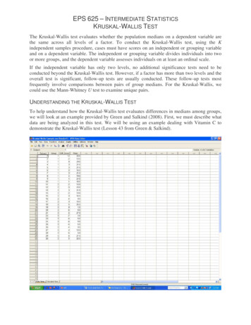
special precautions / SI (METRIC) CONVERSION FACTORSBEFORE YOU BEGINCAUTION12. The minimum distance from combustible material is basedon the combustible material surface not exceeding 160 F.Clearance from the top of the unit may be required to begreater then the minimum specified if heat damage, otherthan fire, may occur to materials above the unit heater atthe temperature described.13. Allow 18" of clearance at rear (or 12" beyond end ofmotor at rear of unit, whichever is greater) and accessside to provide ample air for proper operation of fan.14. The concentric vent adapter box must be installed insideof the structure or building. Do not install this box on theexterior of a building or structure.15. Purging of air from gas supply line should be performedas described in the National Fuel Gas Code, ANSI Z223.1(NFPA 54) - latest edition, or in Canada in CSA-B149codes.16. When leak testing the gas supply piping system, theappliance and its combination gas control must beisolated during any pressure testing in excess of 14" W.C.(1/2 psi).17. The unit should be isolated from the gas supply pipingsystem by closing its field installed manual shut-off valve.This manual shut-off valve should be located within 6’ ofthe heater.18. Turn off all gas before installing appliance.19. C heck the gas inlet pressure at the unit upstream of thecombination gas control. The inlet pressure should be6-7” W.C. on natural gas or 12-14” W.C. on propane. Ifinlet pressure is too high, install an additional pressureregulator upstream of the combination gas control.20. Service or repair of this equipment must be performed bya qualified service agency.21. Do not attempt to reuse any mechanical or electronicignition controller which has been wet. Replace defectivecontroller.CAUTION1. All literature shipped with this unit should be kept for futureuse for servicing or service diagnostics. Leave manual withthe owner. Do not discard any literature shipped with this unit.2. C onsult piping, electrical, and venting instructions in thismanual before final installation.3. D o not attach ductwork, air filters, or polytubes to anypropeller unit heater.In the U.S., the installation of these units must comply with thethe National Fuel Gas Code, ANSI Z223.1 (NFPA 54) - latestedition, or in other applicable local building codes. In Canada,the installation of these units must comply with local plumbingor waste water codes and other applicable codes and with thecurrent code CSA-B149.1.1. All installation and service of these units must beperformed by a qualified installation and service agencyonly as defined in ANSI Z223.1 (NFPA 54) - latest edition orin Canada by a licensed gas fitter.2. This unit is certified with the controls furnished. Forreplacements parts, please order according to thereplacement parts list on serial plate. Always know yourmodel and serial numbers. Modine reserves the right tosubstitute other authorized controls as replacements.3. Unit is balanced for correct performance. Do not alter fanor operate motors at speeds below what is shown in thismanual.4. Information on controls is supplied separately.SI (Metric) Conversion Factorsimportant1. To prevent premature heat exchanger failure, do not locateANY gas-fired appliances in areas where corrosive vapors(i.e. chlorinated, halogenated, or acidic) are present in theatmosphere.2. To prevent premature heat exchanger failure, the input tothe appliance as indicated on the serial plate, must notexceed the rated input by more than 5%. Verify that theblower has been set to the proper RPM for theapplication. Refer to page 17 for Blower Adjustments.3. Start-up and adjustment procedures must be performedby a qualified service agency.6-563.5To Convert Multiply By"W.C.0.249 F( F-32) x 5/9BTU1.06Btu/ft337.3Btu/hr0.000293CFH (ft3/hr)0.000472CFH (ft3/hr)0.00000787CFM (ft3/min)0.0283CFM .89psig27.7To ObtainkPa W.C.3
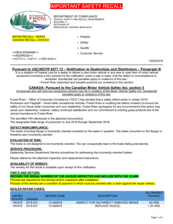
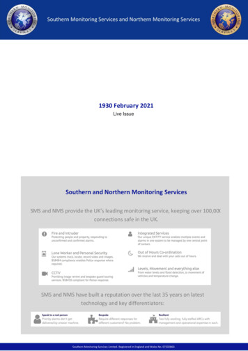
unit locationFigure 4.1 - Combustible Material and ServiceClearancesUNIT LOCATIONDANGERAppliances must not be installed where they may beexposed to a potentially explosive or flammable atmosphere.CAUTION1. Clearances to combustible materials are critical. Be sure tofollow all listed requirements.2. Heaters are designed for use in heating applications withambient temperatures between 40 F and 80 F. Heatersshould not be used in applications where the heated spacetemperature is below 40 F. The combination of low spaceand combustion air temperatures may result in condensatefreezing in the secondary heat exchanger and/orcondensate drain.3. Do not install unit outdoors.4. In garages or other sections of aircraft hangars such asoffices and shops that communicate with areas used forservicing or storage, keep the bottom of the unit at least7’ above the floor unless the unit is properly guarded toprovide user protection from moving parts and interiorsurface temperatures that can cause serious burns iftouched. In parking garages, the unit must be installed inaccordance with the standard for parking structures ANSI/NFPA 88A, and in repair garages the standard for repairgarages NFPA 30A (formerly NFPA 88B). In Canada,installation of heaters in airplane hangars must be inaccordance with the requirements of the enforcingauthority, and in public garages in accordance with thecurrent CSA-B149 codes.5. In aircraft hangars, keep the bottom of the unit at least10' from the highest surface of the wings or engine enclosure of the highest aircraft housed in the hangarsand in accordance with the requirements of the enforcingauthority and/or NFPA 409 - latest edition.6. Installation of units in high humidity or salt wateratmospheres will cause accelerated corrosion resulting ina reduction of the normal life of the units.Table 4.1 - Clearances - Sizes 110 and BelowUnit SideTop and BottomAccess SideNon-Access SideRearVent ConnectorUnit SideTop and BottomAccess SideNon-Access SideRearVent ConnectorTo prevent premature heat exchanger failure, do not locateANY gas-fired appliances in areas where corrosive vapors(i.e. chlorinated, halogenated, or acidic) are present in theatmosphere.1. When locating the heater, consider general space andheating requirements, availability of gas and electrical supply,and proximity to vent locations and condensate drain lines.2. When locating units, it is important to consider that thecombustion air and exhaust vent piping must be connectedto the outside atmosphere. Vent terminals should be locatedadjacent to one another. Maximum equivalent vent lengthsare listed in “Section A - General Instruction - All Units” of theVenting instructions.3. Be sure the structural support at the unit location site isadequate to support the unit's weight. Refer to pages 25 and26 for unit weights. For proper operation the unit must beinstalled in a level horizontal position.41"18"18"18"1"6"18"6"Table 4.2 - Clearances - Sizes 135-310importantLocation RecommendationsClearance To RecommendedCombustible Materials Service Clearance1"1"Clearance To RecommendedCombustible Materials Service Clearance6"6"6"18"18"18"6"6"18"6"4. Do not install units in locations where the flue productscan be drawn into the adjacent building openings such aswindows, fresh air intakes, etc.5. Be sure that the minimum clearances to combustiblematerials and recommended service clearances aremaintained. Units are designed for installation with theminimum clearances as shown in Figure 4.1 and Table 4.1.Clearance from the top of the unit may be required to begreater than 6” if heat damage other than fire could result(such as material distortion or discoloration).6. Do not install units in locations exposed to water spray, rain,or dripping water.7. Mounting Height (measured from bottom of unit) at which unitheaters are installed is critical. Refer to mounting height andheat throw data on page 23 of this manual. The maximummounting height for any unit is that height above which theunit will not deliver heated air to the floor.Sound and Vibration LevelsAll standard mechanical equipment generates some sound andvibration that may require attenuation. Libraries, private officesand hospital facilities will require more attenuation, and in suchcases, an acoustical consultant may be retained to assist in theapplication. Locating the equipment away from the critical areais desirable within ducting limitations. Generally, a unit shouldbe located within 15 feet of a primary support beam. Smallerdeflections typically result in reduced vibration and noisetransmission.6-563.5
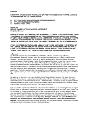
unit mOUNTINGAlternate Suspension MethodsCAUTIONA pipe hanger adapter kit, shown in Figure 5.1 is available asan accessory. One kit consists of two drilled 3/4” IPS pipe capsand two 3/8"-16 x 1-1/2" capscrews to facilitate threaded pipesuspension. Two kits would be required for PTC units and 3 kitsfor BTC units.1. D o not install units below 7' measured from the bottom ofthe unit to the floor in commercial applications (unlessunit is properly guarded to provide user protection frommoving parts and interior surface temperatures that cancause serious burns if touched) and 5' measured from thebottom of the unit to the floor in residential applications(sizes 110 and smaller only).2. Be sure no obstructions block air intake and dischargeof unit heaters.3. The minimum distance from combustible material isbased on the combustible material surface not exceeding160 F. Clearance from the top of the unit may be requiredto be greater than the minimum specified if heat damage,other than fire, may occur to materials above the unitheater at the temperature described.4. Allow 18" clearance at rear (or 12" beyond end of motorat rear of unit, whichever is greater) and access side toprovide ample air for proper operation of fan.Figure 5.1 - Unit Heater Suspension MethodsPipe Adaptor Kit1. Be sure the means of suspension is adequate to
by Modine Manufacturing Co. All models approved for use in California by the CEC and in Massachusetts. Unit heater is certified for residential (size 110 and smaller only) and commercial applications. WARNING 1. Improper installation, adjustment, alteration, service, or maintenance ca