Transcription
TECHNICAL NOTERevisions to BS8006 forreinforced soil – what dothese mean for the industry?By Stephen P Corbet, Aecom, (Chairman BSi B526/4 Reinforcedand Strengthened Soils), Chris Jenner, Tensar International UK,Graham Horgan, Huesker UK.Presented at the Ground Engineering Slopes Conference on 16 November 2010.Over the past 15 years, the designof reinforced soil structures hasevolved from the principles setout in the first edition of BS8006,published in 1995. The introductionof Eurocodes made a revision toBS8006:1995, essential as EN19971 specifically excludes the design ofreinforced soil structures and slopes.The BSi has completed the revision of BS8006 and Part 1, whichcovers the design of reinforced fillswas published at the end of 2010,while Part 2, which covers thedesign of reinforced insitu soils, isdue to be published this year.IntroductionSince the publication of BS8006 in1995 after 10 years of drafting incommittee, the design of reinforcedsoil structures has evolved as theresults from research have improvedthe understanding of the behaviourreinforcement in soil.The publication of the Eurocodesfor design has resulted in the needto withdraw or revise all existingdesign codes in the UK and Europe.The Eurocode EN1997-1 Geotechnical Design does not include anyprovision for the design of reinforced soil structures and the UKNAD makes a clear statement tothis effect.In particular, the factors to beapplied to the strength of the reinforcing elements cannot be determined from the Eurocode.Structure of the codeThe standard will be published intwo parts: Part 1: Reinforced Fills– Retaining walls, slopes, basal reinforcement and transfer platforms;and Part 2: Strengthened InsituSoils – Soil nails.The two parts recognise that thedesign of insitu soils reinforced withsoil nails is completely different tothe reinforcement of soils placed26as fills. Part 2 will be based on theCIRIA C637 Soil Nailing – BestPractice Guidance, but with moreemphasis on the design of reinforced soil slopesThe changesThe BSi committee of experts hasreviewed the whole document andthe following changes have beenmade. The changes were made public in a draft for public comment,published in July 2009, and thecomments received were incorporated into the final document.n Clauses and information whichconflicted with BSEN1997-1, BSEN14475 & BSEN 14490 have beenremoved, but we have not revisedall terminology to agree with BSEN1997-1.n The correction of some outstanding errors found in text (at least twofound in the last published version).n The partial factors were reviewed.The review was to look at the possibility that the partial factors inBS8006 could be the same or veryclose to the partial factors used inEN1997-1. The current situation isthat the partial factors in BS8006will remain unchanged.n A new section on reinforced modular block walls has been added tocover this new technology.n The design of facings for slopesand walls has been reviewed.n All text previously included bythe Highways Agency in BD70, hasbeen moved to BS8006-1 for bridgeabutments and bank-seats.n The construction details havebeen revised, with more information included for information.n Advice on the use of vegetation onsteep slopes is included. The adviceincludes information about the bestmethods for getting grass and othervegetation to grow and survive.n The problems associated with lateral forces at the edges of embank-ments with basal reinforcementand with piles or other foundationimprovements have been addressed.n In Annex A the derivation of partial factors for polymeric reinforcement has been updated to follow theprinciples described in PD ISO CR20432: 2007.n A new Annex has been addedwith seismic effects on reinforcedsoil structures, based on experiencesform Japan and US, with cross reference to BSEN 1998.n Other Annexes giving test procedures have been reviewed andremoved where now described intesting standards.n New features include: The useof recycled materials is encouragedusing the Highways Agency document HD35/04 as a basis; cohesivefills can benefit from inclusionsof drains within the soil layers toreduce the drainage paths for excesspore water pressure; new reinforcements can be considered, such as– electro-kinetic geosynthetics, usedto set up an electro osmosis systemfor rapid drainage; low strain/highstrength geogrids.Sections 6 and 7 reinforcedsoil walls and steep slopes –concepts and fundamentalprinciples (Jenner)To satisfy the requirements of alimit state code, partial load factorsare applied to the actions and material factors are applied to the material properties.Once the factors have beenapplied, the requirement for stability is that the design restoring forcesand moments should be greaterthan the design disturbing forcesand moments. In a particular application, the load factors applied todead loads and live loads can varydepending on the load combinationunder consideration; in some circumstances, the partial load factorsfor live loads may be set at zero toproduce a worst-case combinationfor the design load.The loads, both dead and live, arecalculated in their unfactored formas characteristic values, which thenhave the appropriate partial factorapplied to give the design load.The resisting forces in any application are generated from the available shear strength of the soil andthe tensile strength of the reinforcing elements.The shear strength of the soil,allowing for any pore pressure,should be a characteristic valuedetermined as a cautious estimateof the value recognising the limitstate under consideration. For wallsand slopes, the peak friction angleis used. In all applications, the consideration of external, internal andcompound stability is required. Forinternal and compound stability,the resistance provided by the soil issupplemented by the strength of thereinforcement.The reinforcement strength isderived following a proceduredescribed in an Annex of the document.Reinforcement is defined as beingextensible if the design strength issustained at a total axial strain value 1%, and inextensible if the designstrength is sustained at a total axialstrain 1%. This definition candetermine the actual design methodadopted for a particular application.The Code of Practice is applicable to all types of geosynthetic andsteel soil reinforcement.Vertical walls and bridgeabutmentsThe principles described in theprevious section apply to bothreinforced soil walls and bridgeabutments, which are designed asvertical structures.Other structures with facingground engineeringApril 2011
EffectsReinforced slopesCombinationsADead load of the structureffs 1.5BCffs 1.0ffs 1.0Dead load of the fill on top of the structureffs 1.5ffss 1.0fs 1.0Dead load of bridge and bank seatff 1.2ff 1.0ff 1.0Backfill pressure behind the bank seatffs 1.5ffs 1.5ffs 1.0Backfill pressure behind the structureffs 1.5ffs 1.5ffs 1.0Horizontal loads due to creep and shrinkageff 1.2ff 1.2ff 1.0Traffic loadingOver theentirestructure,fq 1.5Behind the reinforcedzone, fq 1.5HAfq 1.5fq 1.5HA and HBfq 1.3fq 1.3HAfq 1.25fq 1.25HA and HBfq 1.1fq 1.1fq 1.3fq 1.3Bridge vertical live loadBraking dynamic loadTemperature effectsTable 1: Partial load factors for wallsSoil materialfactorsTo be applied tan f′ fms 1.0fms 1.0fms 1.6fms 1.0To be applied to c′To be applied to cuSoil/reinforcementinteractionfactorsfms 1.0fms 1.0Sliding acrosssurface ofreinforcementfs 1.3fs 1.0Pull-out resistanceof reinforcementfp 1.3fp 1.0Partial factors Foundation bearing fms 1.35of safetycapacity: to beapplied to qultSliding along baseof structure or anyhorizontal surfacewhere there issoil-to-soil contactfs 1.2n/an/aTable 2: Partial load factors for abutmentsangles within 20 of the vertical canalso be designed as vertical structures to the Code. Table 17 (Table 1above) of the Code gives the partialload factors for load combinationsassociated with walls and Table 18(Table 2 above) gives the same information relating to bridge abutments.Soil material factors can beextracted from Table 16 (Table 3overleaf) with a number of partialfactors of safety relating to soil/reinforcement interaction, foundation bearing capacity and slidingalong the base of the structure.The most adverse loads likely tooccur should be considered.ground engineeringApril 2011Design methods for wallsThe wall design approach isbased on the classification of thereinforcement materials, whetherthe reinforcement is extensible orinextensible.Extensiblereinforcementisdesigned using the Tie-Back Wedgemethod where the stress conditionwithin the reinforced soil block istaken to be an active stress state andwall friction on the back of the blockis zero (see Figure 1).When inextensible reinforcementis used, the Coherent Gravity designmethod is used with a stress condition within the reinforced soil blockthat varies between the “at-rest”condition in the upper zone reducing to active conditions deeper inthe structure with wall friction calculated (see Figure 2).Ultimate limit stateThe appropriate partial factors areapplied to the loads and materialsdepending on the Load Case underconsideration. Load Case A, withmaximum factors applied throughout, is normally the critical condition for reinforcement capacity andfoundation bearing pressure andsometimes governs reinforcementanchorage.Load case B, with minimum massof the structure but maximum overturning forces, is normally criticalfor sliding along the base of the reinforced soil block and reinforcementanchorage.Serviceability limit stateLoad Case C, with dead loads onlyand partial factors of unity, is usedto determine the serviceability limitstates of foundation settlement andreinforcement tension for internalstrains. The limit value of reinforcement tension in the serviceability check is defined by a theoreticalpost-construction strain value.For a wall, the limit is 1% andtherefore the SLS allowable loadcarrying capacity is the value atwhich the reinforcement wouldstrain 1% between the end of construction and the end of the designlife (Figure 3, overleaf). For an abutment, the limiting post-constructionstrain is 0.5%.The design methods for reinforcedslopes, generally defined as thoseslopes with face angles greater than20 to the vertical, are all derivedfrom limit equilibrium methods,originally derived for unreinforcedslopes. The Code does not limit themethods that can be used for design,provided that they can be adaptedto a limit state format. However,it does describe the most commonmethods in some detail.The partial factors are definedin Table 4 (overleaf). with onlytwo load cases, ULS and SLS. Thefriction angle of the fill should bedefined as the peak value and, aswith the wall design, there are partial factors of safety applied to soil/reinforcement interaction and sliding along the base.The requirement for the inclusionof the Moment Correction Factor chas been removed in the revised version of the BS. Any potential failuresurface that passes around the reinforced soil zone without cutting alayer of reinforcement is now analysed using the approach defined inEurocode 7.For reinforced slopes where theface angle is 45 or less the need fora formal facing may not be required.In those situations the reinforcement capacity close to the front facemay be limited because of bond,although higher shear strengths maybe mobilised because of the lowconfining stress. A check of superficial stability can be carried out toassess the stability of a free face inresistance to sliding on a plane thatis very close, and parallel, to theslope surface.It is noted in the code that compoundstabilityconsiderationswhere a slip surface passes partiallythrough the reinforced fill and partially through the unreinforced fillmay well be the critical situation.Section 8 – basalreinforcement and loadtransfer platforms (Horgan)UK BS8006-1 2009 Section 8 – basalreinforcement and basal reinforcement over piles (aka load transferplatforms), updates the previousguidance and attempts to expand/clarify guidance considered ambiguous in the previous draft and toreflect changes in best practice sinceBS8006 was first published in 1996.The main additional issuesaddressed in the updates relate to:n Consideration of pile capgeometry;n Consideration of alternativearching mechanisms;n More emphasis on assessing/controlling the settlementsbetween piles;n Greater emphasis on collabo27
TECHNICAL NOTEration between geosyntheticsand pile designers;n Time dependant consolidation ofsoil between piles and considerationof partial support between piles;n Additional guidance on anchorage details etc.Selection of soil parametersand partial factorsThe British standard differentiatesbetween soils/fills used in slopesand walls and those used in embankments. Since the strains induced inmultiple layer reinforcement such aswalls and slopes are deemed small,the frictional strength is representedby tanφp’, the peak effective angle ofinternal shearing resistance. Largerstrains are allowed in other scenarios, for example an embankmentsubject to differential settlement.In these cases, the frictionalstrength is represented by largestrain values. For cohesionless soilsthis is the value when the soil shearsat constant volume.Consideration of foundationFigure 2: Coherent gravity stress state0KoKaKjJHArc tan 0.36mWs2Ws1zSoil 1:c’1 φ1 γ1 κ1Soil 2:c’2 φ’2 γ2 κ2TWhjβTpjHPb 0 for tie backwedge method.b (1.2 – L/H) f2for coherent gravitymethodL-2eLSoil materialfactorsReinforcementmaterial factorSoilreinforcementinteractionfactorsPartial factorsof safetyPartial FactorsUltimate limit stateServiceability limitstateSoil unit mass eg slope fillffs 1.5fs 1.0External deal loads eg lineor point loadsff 1.2ff 1.0External live loads eg trafficloadingfq 1.3fq 1.0To be applied tan frfms 1.0fms 1.0To be applied to c’fms 1.6fms 1.0To be applied to thereinforcement base strengthThe value of fm should be consistentwith the type of reinforcement to beused and the design life over which thereinforcement is required (see 5.3 andAnnex A)Sliding across surface orreinforcementfs 1.3fs 1.0Pull out resistance ofreinforcementfp 1.3fp 1.0Sliding along base ofstructure where there issoil-to-soil contactfs 1.2NATable 3: Partial factors for reinforced slopes28Isochrone for end of constructionIsochrone for end of design lifePrescribed post-construction strain limitFigure 3: Assessment of post-construction strainFigure 1: Stressed imposed by the soils and surchargesLoad factorsTcsεsoils: BS8006-1 assumes that all ofthe embankment loading will betransferred through the piles downto a firm stratum either by directarching on the pile caps or by theload carried to the piles by the geosynthetic reinforcement.Consequently, the characteristicsof the soft foundation soil is considered only with regard to the typeof piles used and their installation.However, the time dependant consolidation of soil between piles issubsequently discussed.BS 8006:1996 was one of the firstnational codes to adopt limit stateprinciples and these are maintainedin the updated code.Consideration of pilecap geometryThe original guidance did not differentiate between circular or squarepile caps of equal dimension yet thearea ratio of the square pile cap (a2)is different to that of a circular cap(πD2/4). Yet this dimension is usedsubsequently used to determine theamount of arching (Marston’s ratio)or stress redistribution that occurswithin the piled embankment. Thenew guidance recommends reducing the design dimensions of cir-ground engineeringApril 2011
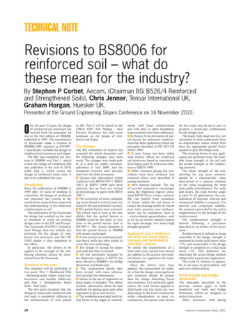
Surcharge WsEmbankmentOutwardshear stressLoReinforcementFill: γ,φ’cvPfillLbOptional geotextile separator(dependant on embankment fill material)HMinimum cover500mm toreinforcementAnchor bond length(varies)BRP layerdepth can varyLdsLpPilecapsSoft foundationEdge trenchoption detailPilesFigure 4: anchorage length (Lb) at the edge of the piled areaPartial factorUltimate limitstatePiles with pile caps(pre-cast driven, vibro concrete columnsdriven/cast insitu, continuous flight auger)Serviceabilitylimit stateFigure 5: Reinforcement anchorage at edge of fillLoad factorsSoil unit mass,eg embankment fillffs 1.3ffs 1.0Pile arrangementArching coefficientExternal dead loads,e.g. line or point loadsff 1.2ff 1.0End-bearing piles(unyielding)Cc 1.95H/ a -0.18External live loads, e.g.traffic loadingfq 1.3fq 1.0Friction & other pilesCc 1.5H/ a -0.07Soil material factorsmined by using Marston’s formula:To be applied to tan φ’fms 1.0fms 1.0To be applied to c’fms 1.6fms 1.0To be applied to cufms 1.0fms 1.0Soil/reinforcement interaction factorsSliding across surfaceof reinforcementfs 1.3fs 1.0Pull-out resistance ofreinforcementfp 1.3fp 1.0Table 4: BS8006 Section 8 Partial factorscular pile caps to consider a squarepile of an equivalent area. Wherecircular pile caps are to be used,the diameter of the pile should bereduced to produce an effective pilecap width aequ,aequ (πD2/4)0.5 hence aequ 0.886Dwhere:a is the size of the pile caps(assuming full support can be generated at the edges of the caps);D is the diameter of the pile capDetermination of load actingacross the reinforcementDue to the significant differencesin deformation characteristics thatexist between the piles and the surrounding soft foundation soil, thevertical stress distribution across thebase of the embankment is assumedto be non-uniform. Soil archingbetween adjacent pile caps inducesgreater vertical stresses on the pilecaps than on the surrounding adja-ground engineeringApril 2011Table 5: Arching coefficient Cccent soil.BS8006-1 identifies a minimumheight whereby partial archingbegins to develop but additionalloads placed at the surface of theembankment still influence the loadcarried by the reinforcement. Thisminimum height is :H 0.7(s – a)where:a is the size of the pile caps (or aequconsidering circular pile caps)s is the spacing between adjacentpilesBS8006-1 also identifies a critical height concept above which anyadditional embankment weight orsurcharge loading placed at the surface of the embankment is deemedto pass directly to the pile caps andnot influence the reinforcement.The ratio of the vertical stressexerted on top of the pile caps tothe average vertical stress at the baseof the embankment may be deter-[ ]P’c Ccas’vH2where:P’c is the vertical stress on thepile caps;s’v (ffsγH fqws) and is the factored average vertical stress at thebase of the embankment;γ is unit weight of the embankment fill;H is the height of the embankment;ws is the uniformly distributedsurcharge loading;a is the size (or diameter) of thepile caps;Cc is the arching coefficient.Where the value of the arching coefficient will vary depending on thetype of piles.Several authors have studied andcompared the phenomena of soilarching using a variety of physical,analytical and numerical models totry to gain a better understandingand quantify the load acting acrossthe reinforcement and distributingdirectly to the pile caps (Alexiew2002, Eekelen 2008, Kempton et al1998, Love and Milligan 2003, Rogbeck 1998, Stewart and Filz, 2005).One criticism of the original codeis that the distributed load actingacross the reinforcement was verysensitive to embankment heightsaround the critical heightH 1.4(s – a)Embankment heights just underthis limit would result in considerably more design load acrossthe reinforcement than embankment heights just above this level.Additional criticism related to thefact the ratio of the vertical stressexerted on top of the pile caps tothe average vertical stress at the baseof the embankment was dependantsolely on pile type and independentof the type of fill used within theembankment.Finally a criticism that verticalequilibrium is not satisfied (Eekelen,2008). However, neither the load acting across the reinforcement nor theincreased load acting on the pile capsare calculated directly, but ratherindirectly from the ratio of increasein stress concentration on the pilecaps to the average vertical stress atthe base of the embankment.BS8006-1 2009 Section 8 allowsfor an alternative theoretical solution which may be used to determine the vertical load acting acrossthe reinforcement based on workpresented by Hewlett and Randolph, 1998, which was based onthe observed failure mechanismfrom model tests and considers aseries of hemispherical domes. Thetheory determines the efficacy E asthe proportion of the embankmentweight carried by the piles, hencethe proportion of the embankmentweight carried by the geosyntheticreinforcement may be determined(1 E).The original guidance utilisesMarston’s formula to determine thedistributed load acting across thereinforcement29
TECHNICAL NOTEWT []1.4 sffsg (s – a) 2 2s – a (p’/s’v)s2 – a2where:WT is the distributed vertical loadacting on the reinforcement betweenadjacent pile caps;ffs is the partial load factor for soilunit weight (see Table 1);fq is the partial load factor forexternal applied loads (see Table 1).To satisfy vertical equilibriumthen the remaining load must becarried directly by the pile caps, WPWP (f fsgH fqws ) s2 – WT (s2 – a2)(although this formulation is notprovided in BS8006 -1 2009). Oncethe distributed load WT acting acrossthe reinforcement is determined,then for an extensible reinforcement the tensile load Trp per metrerun, generated in the reinforcementresulting from the distributed loadWT is determined by1Trp WT (s – a) 1 6ε2awhere:Trp is the tensile load in the reinforcement;ε is the strain in the reinforcement.The above equation has twounknowns Trp and ε, and may besolved for Trp by assuming a maximum allowable strain in the reinforcement and by an understandingof the load/strain characteristics ofthe reinforcement at different loadlevels. Initial tensile strain in thereinforcement is needed to generate a tensile load; BS8006 stipulatesthat a practical upper limit of 6%strain should be imposed to ensureall embankment loads are transferred to the piles.In addition to the load on thereinforcement generated by theredistributed vertical embankmentload, the reinforcement needs toresist the outward thrust from theembankment. The reinforcementtensile load Tds needed to resist theoutward thrust of the embankmentmay be taken asTds 0.5Ka (ffsγH 2fqws)Hwhere:Tds is the tensile load in the reinforcement per metre run neededto resist the lateral thrust of theembankment fill;Ka is the active earth pressurecoefficient [ tan2(45 – fcv/2)];H is the height of the embankment;γ is the unit weight of the embankment fill;ws is the surcharge intensity ontop of the embankment;30ffs is the partial load factor for soilunit weight (see Table 1);fq is the partial load factor forexternal applied loads (see Table 1).Reinforcement detailsThe design approach essentiallydetermines the requirement for twoorthogonal layers of geosyntheticreinforcement at the base of thepiled embankment, one longitudinallayer parallel along the centre line ofthe embankment and one transverselayer perpendicular across the lineof the embankment.The longitudinal reinforcement isdesigned to resist the redistributedvertical load Trp.The transverse reinforcement isdesigned to resist both redistributedvertical load Trp and to resist the lateral thrust of the embankment Tds.To mobilise these loads the reinforcement should achieve an adequate bond with the adjacent soilat the extremities of the piled areato ensure that the maximum limitstate tensile loads can be generatedbetween the outer two rows of piles.Across the width of the embankment the reinforcement shouldextend a minimum distance (Lb)beyond the outer row of piles, (seeFigure 4).The reinforcement may beextended around the row of gabionsand returned into the embankmentfill to develop the necessary bondlength (see Figure 5).Depending on the geometry ofthe embankment, it may be difficultto achieve an adequate bond lengthat the extremity of the piles bymaintaining the reinforcement in ahorizontal alignment as depicted inFigure 4. One solution that may beconsidered is to use a row of gabions, as a thrust block along the topof the outer row of piles.Another detail that may be considered is the inclusion of a smallperiphery trench just beyond theedge piles, running parallel to thecentreline of the embankment; thetrench is typically only as deep asthe piling mat or pile cap depth. Thereinforcement can be extended intothe trench and when backfilled, willreturn into the embankment fill todevelop the necessary bond.Time dependant consolidationof soil between pilesBS8006-1 assumes that all of theembankment loading will be transferred through the piles down to afirm stratum either by direct arching on the pile caps or by the loadcarried to the piles by the geosynthetic reinforcement. In reality, thesoil between the piles will need toundergo some initial degree of consolidation to enable tensile forces inthe geosynthetic to be mobilised.This settlement can be related toan increase in stress from the installation of the temporary workingplatform or as a result of initial fillplacement or by external factorssuch seasonal fluctuations in theground water level increasing theeffective stress on the insitu soil.Hence the time dependant consolidation of soil between piles isimportant in reaching the assumedend design condition of no partialsupport between piles.Consideration can also be givento the introduction of a compressible layer between the pile caps toensure deflection of the geosynthetic during the initial placement of theoverlying fill.The maximum mid-span deflection y of extensible reinforcement,spanning between pile caps, may bedetermined from the formulationbelow (after Giroud)y (s – a)3ε8where:a is the size of the pile caps;s is the spacing between adjacentpiles;ε is the strain in the reinforcement.The thickness of the compressiblelayer can be such that it can accommodate the deflection of the geosynthetic during the early stages ofembankment construction, ensuringthat the assumed design deflectionsare achieved.ConclusionsBS8006 was first published in 1995.Section 8 of the code has been usedto successfully design a vast numberof piled supported embankmentsworldwide.BS8006-1 2009 updates the previous guidance to reflect better industry understanding of the behaviourof such complex earthworks and toreflect changes in best practice.Currently there is a variety of different design approaches, which differ mainly in the amount of archingconsidered and the degree of support offered by the existing sub soil.The BS8006-1 assumption thatall of the embankment loading willbe transferred through the piles orby the geosynthetic reinforcementonto the piles can be consideredconservative.However, the potential useof compressible layers beneaththe geosynthetic reinforcementbetween pile caps can ensure thatthe end design condition of nopartial support between piles canbe achieved during construction.This would make considerationof the time dependant consolidation of soil largely academic.ReferencesBS 8006:-1:2010 Code of Practice forStrengthened/reinforced soils and fills,BSi London 2010.BS EN 1997-1:2005 GeotechnicalDesign, BSi London 2005CIRIA C637 Soil Nailing – best practice guidance CIRIA 2005.PD ISO CR 20432 Guidelines for thederivation of the longterm strength ofgeosynthetics for soil reinforcementHD 35/04 Conservation and the Useof Secondary and Recycled MaterialsAASHTO (1998), Interim StandardSpecifications for Highway Bridges,AASHTO, Washington DC, 16thEdAlexiew, D., Piled embankmentdesign: Methods and case studies, Proc.XV Italian Conference on Geosynthetics, Bologna,October 2002. In:L’ingegnere e l’architetto, Special Issue1-12/2002. pp. 32-39. 2002.DIN 1054:2005-01 Baugrund; Sicherheitsnachweise im Erdund Grundbau.Eekelen, van SJM, Van, MA, Bezuijen, A. Design of piled embankmentsconsidering the basic starting point ofthe British Standard BS8006. Proceedings of the Fourth European Geosynthetics conference. Edinburgh,FHWA(1996) Mechanically StabilizedEarth Walls and Reinforced Soil SlopesDesign and Construction Guidelines”(FHWA-SA-96-071).Giroud, JP, (1995). Technical Note:Determination of geosynthetic straindue to deflection, Geosynthetics International, Vol. 2, No.3, pp.635-641Hewlett, WJ, Randolph, MA.Analysis of Piled Embankments.Ground Engineering. April pp.12-18.1988Kempton, G.T., Russell, D., Pierpoint, N.D., Jones, C.J.F.P. Two andthree-dimensional numerical analysis ofthe performance of piled embankments.Sixth international conference ongeosynthetics, Atlanta, Georgia.pp.767-772. 1998.Love J, Milligan G. Design methods for basally reinforced pile-supportedembankments over soft ground, GroundEngineering, Vol. 36, No. 3. 2003.Rogbeck, Y, Gustavsson, S,Södergren, I Lindquist, D. Embankment support over piles using geogrids.Sixth international conference ongeosynthetics, Atlanta, Georgia.pp.755-762. 1998.Stewart, ME, Filz, GM. Influenceof Clay compressibility on GeosyntheticLoads in Bridging Layers for ColumnSupported Embankments, GSP 131Contemporary Issues in FoundationEngineering, Geofrontiers 2005,Austinground engineeringApril 2011
26 ground engineering April 2011 By Stephen P Corbet, Aecom, (Chairman BSi B526/4 Reinforced and Strengthened Soils), Chris Jenner, Tensar International UK, Graham Horgan, Huesker UK. Presented at the Ground Engineering Slopes Conference on 16 November 2010. O ver the past 15 years, the design of reinforced soil structures has