Transcription
IntroducingVirtual SwitchSystem (VSS)Philip NedevSECisco Bulgariapnedev@cisco.comPresentation ID 2006 Cisco Systems, Inc. All rights reserved.Cisco Public1
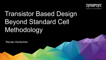
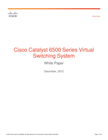
Virtual Switching Supervisor Engine 720 w/ 10GEQ4CY07UplinksNew Sup720-10GE Features:IOS: 12.2(33)SXHBoth GE and 10GE Uplink Ports.– 2 x 10GE (X2 Optics) : VSL Capable–100 MB Per Port Ingress/Egress Buffering– 2 x GE (SFP Optics) : GE & 10/100/1000– 1 x GE (10/100/1000)– All uplinks active in redundant configuration– All uplinks share 20G Channel to Backplane PFC3C/PFC3CXL included Compatible with all chassis (E- and non-E series)Presentation ID 2006 Cisco Systems, Inc. All rights reserved.Cisco Public2
Agenda Hardware and Software Update Switched Network Design Challenges VSS Introduction VSS Technical Details Advantages and deployment scenarios High Availability Results SummaryPresentation ID 2006 Cisco Systems, Inc. All rights reserved.Cisco Public3
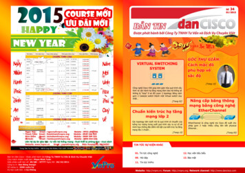
Current Network ChallengesEnterprise CampusTraditional Enterprise Campus deployments have been designed in such a way that allows forscalability, differentiated services and high availability. However they also face manychallenges, some of which are listed in the below diagram L3 CoreL2/L3DistributionAccessPresentation ID 2006 Cisco Systems, Inc. All rights reserved.Cisco PublicExtensive routingtopology, RoutingreconvergenceFHRP, HSRP, VRRPSpanning TreePolicy ManagementSingle active uplinkper VLAN (PVST), L2reconvergence4
Current Network ChallengesData CenterTraditional Data Center designs are requiring ever increasing Layer 2 adjacencies betweenServer nodes due to prevalence of Virtualization technology. However, they are pushing thelimits of Layer 2 networks, placing more burden on loop-detection protocols such as SpanningTree FHRP, HSRP, VRRPSpanning TreePolicy ManagementL2/L3 CoreSingle active uplink perVLAN (PVST), L2reconvergence,excessive BPDUsL2DistributionDual-Homed Servers tosingle switch, Singleactive uplink per VLAN(PVST), L2reconvergenceL2 AccessPresentation ID 2006 Cisco Systems, Inc. All rights reserved.Cisco Public5
Agenda Hardware and Software Update Switched Network Design Challenges VSS Introduction VSS Technical Details Advantages and deployment scenarios High Availability Results SummaryPresentation ID 2006 Cisco Systems, Inc. All rights reserved.Cisco Public6
Virtual Switching SystemVirtual Switch System is a new technology break through for the Catalyst 6500 family Presentation ID 2006 Cisco Systems, Inc. All rights reserved.Cisco Public7
Virtual Switching System 1440Network System VirtualizationCore/DistributionSiSiData Center AccessSiSiSiSiSiSiFeaturesBenefits of VSSNetwork System VirtualizationIncreased Operational Efficiencyvia Simplified NetworkInter-Chassis Stateful SwitchOver (SSO)Boost Non-stop CommunicationMulti-Chassis EtherChannel(MEC)Scale the System BandwidthCapacity to 1.4 TbpsPresentation ID 2006 Cisco Systems, Inc. All rights reserved.Cisco Public8
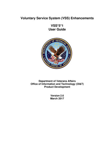
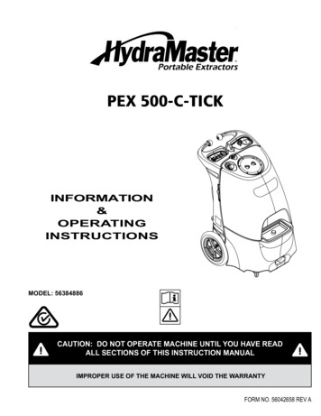
Increased Operational EfficiencySystem Virtualization Simplifying the NetworkSiSiSiSiTraditional L2/L3VSSComplex STP configuration andManagementLoop Free Topology with MECNot Dependant on STPHSRP/VRRP- 3 IP addressNo HSRP/VRRP- 1 IP addressManage Two Nodes and ConfigManage Single Node and ConfigManage additional routing peersManage reduced routing peersPresentation ID 2006 Cisco Systems, Inc. All rights reserved.Cisco Public9
Boost Non-Stop CommunicationInter Chassis Stateful FailoverHSRPSTPIGPSiXSiNSFSSOXSiSiActive–Active Data Plane with 1440 Gbps Switching CapacityActive–Hot Standby Control Plane with NSF/SSO RedundancyTraditional L2/L3VSSConfigure and Maintain MultipleControl ProtocolsEliminate and Minimize ControlProtocolsControl Protocols not Syncneeding re-convergenceInter-chassis SSO - No reconvergenceIndertministic STP basedconvergenceDeterministic sub-secondconvergencePresentation ID 2006 Cisco Systems, Inc. All rights reserved.Cisco Public10
Scale the System Bandwidth Capacity to 1.4 TbpsMulti-Chassis Etherchannel (MEC)Data Center AccessCore/DistributionSiSiSiSiData Center AccessCore/DistributionSiSiTraditional L2/L3SiSiVSSIdling or Underutilized Links inCampus AccessMaximum Bandwidth withEterhchannel LoadbalancingStandby links or NIC teaming onServersActive/Active LACP to Serversto Redundant SwitchesUnicast Flooding Due toAsymmetrical RoutingNo Unicast FloodingPresentation ID 2006 Cisco Systems, Inc. All rights reserved.Cisco Public11
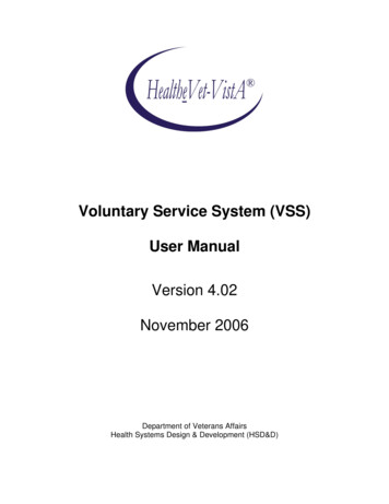
High Availability Campus DesignSimplified with VSSAccessSiSi SiDistributionSi SiCoreSiSi SiSi SiSiSi SiSi SiSi SiSi SiSiSiDistributionAccessPresentation ID 2006 Cisco Systems, Inc. All rights reserved.Si SiSiSi SiSi Si SiWANWANWANCisco PublicSi SiDataDataDataCenterCenterCenterSi SiSi SiInternetInternetInternet12
Introduction to Virtual SwitchConceptsPresentation ID 2006 Cisco Systems, Inc. All rights reserved.Cisco Public13
Virtual Switch SystemBenefitsPresentation ID 2006 Cisco Systems, Inc. All rights reserved.Cisco Public14
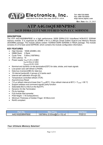
Hardware RequirementsVSL Hardware RequirementsThe Virtual Switch Link requires special hardware as noted below Presentation ID 2006 Cisco Systems, Inc. All rights reserved.Cisco Public15
VS-S720-10GSwitch FabricPresentation ID 2006 Cisco Systems, Inc. All rights reserved.Cisco Public16
VS-S720-10GPFC3C and PFC3CXLPresentation ID 2006 Cisco Systems, Inc. All rights reserved.Cisco Public17
Virtual Switch ArchitectureVirtual Switch DomainA Virtual Switch Domain ID is allocated during the conversion process and represents thelogical grouping the 2 physical chassis within a VSS. It is possible to have multiple VSDomains throughout the network VS Domain 10VS Domain 20VS Domain 30The configurable values for the domain ID are 1-255. It is always recommended to use a uniqueVS Domain ID for each VS Domain throughout the network Presentation ID 2006 Cisco Systems, Inc. All rights reserved.Cisco Public18
Virtual Switch ArchitectureVirtual Switch LinkThe Virtual Switch Link is a special link joining each physical switch together - it extends the outof band channel allowing the active control plane to manage the hardware in the secondchassis Presentation ID 2006 Cisco Systems, Inc. All rights reserved.Cisco Public19
Virtual Switch ArchitectureForwarding OperationIn Virtual Switch Mode, while only one Control plane is active, both Data Planes (SwitchFabric’s) are active, and as such, each can actively participate in the forwarding of data Switch 1 - Control Plane ActiveSwitch 2 - Control Plane Hot StandbyVirtual Switch DomainSwitch 1 - Data Plane ActiveSwitch 2 - Data Plane ActiveVirtual Switch DomainPresentation ID 2006 Cisco Systems, Inc. All rights reserved.Cisco Public20
Virtual Switch ArchitectureRouter MAC AddressIn a standalone Catalyst 6500 system, the router MAC address is derived from the ChassisMAC EEPROM and is unique to each Chassis. In a Virtual Switch System, since there is only asingle routing entity now, there is also only ONE single router MAC address Router MAC 000f.f8aa.9c00The MAC address allocated to the Virtual Switch System is negotiated at system initialization.Regardless of either switch being brought down or up, the same MAC address will be retainedsuch that neighboring network nodes and hosts do not need to re-ARP for a new address.Presentation ID 2006 Cisco Systems, Inc. All rights reserved.Cisco Public21
Etherchannel ConceptsMultichassis EtherChannel (MEC)Prior to Virtual Switch, Etherchannels were restricted to reside within the same physicalswitch. In a Virtual Switch environment, the 2 physical switches form a single logical networkentity - therefore Etherchannels can now also be extended across the 2 physical chassis Virtual SwitchVirtual SwitchLACP, PAGP or ON Etherchannelmodes are supported Regular Etherchannel on single chassisPresentation ID 2006 Cisco Systems, Inc. All rights reserved.Cisco PublicMultichassis EtherChannel across 2 VSLenabled Chassis22
Etherchannel ConceptsEtherchannel Hash for MECDeciding on which link of a Multi-chassis Etherchannel to use in a Virtual Switch is skewed infavor towards local links in the bundle - this is done to avoid overloading the Virtual SwitchLink (VSL) with unnecessary traffic loads Blue Traffic destined forthe Server will result inLink A1 in the MEC linkbundle being chosen asthe destination path Orange Traffic destinedfor the Server will result inLink B2 in the MEC linkbundle being chosen asthe destination path Link A1Link B2ServerPresentation ID 2006 Cisco Systems, Inc. All rights reserved.Cisco Public23
Operational ManagementVirtual Switching System CLIMultiple console interfaces exist within a Virtual Switch Domain, but only the active RP/SPconsoles are enabled for command interaction Presentation ID 2006 Cisco Systems, Inc. All rights reserved.Cisco Public24
Operational ManagementSlot/Port NumberingAfter conversion, port definitions for switches within the Virtual Switch Domain inherit theChassis ID as part of their naming convention PORT NUMBERING: CHASSIS-ID SLOT-NUMBER PORT-NUMBER Chassis-ID WILL ALWAYS be either a “1” or a “2”VSS#show ip interface upupupup snip Presentation ID 2006 Cisco Systems, Inc. All rights reserved.Cisco Public25
Virtual Switch NetworkingEnterprise CampusA Virtual Switch-enabled Enterprise Campus network takes on multiple benefits includingsimplified management & administration, facilitating greater high availability, while maintaininga flexible and scalable architecture L3 CoreL2/L3DistributionAccessPresentation ID 2006 Cisco Systems, Inc. All rights reserved.Cisco PublicReduced routingneighbors, MinimalL3 reconvergenceNo FHRPsNo Looped topologyPolicy ManagementMultiple activeuplinks per VLAN, NoSTP convergence26
Virtual Switch NetworkingData CenterA Virtual Switch-enabled Data Center allows for maximum scalability so bandwidth can beadded when required, but still providing a larger Layer 2 hierarchical architecture free ofreliance on Spanning Tree Single router node, FastL2 convergence,Scalable architectureL2/L3 CoreDual Active Uplinks,Fast L2 convergence,minimized L2 ControlPlane, ScalableL2DistributionDual-Homed Servers,Single active uplink perVLAN (PVST), Fast L2convergenceL2 AccessPresentation ID 2006 Cisco Systems, Inc. All rights reserved.Cisco Public27
Virtual Switch PositioningDeployment Scenario #1Presentation ID 2006 Cisco Systems, Inc. All rights reserved.Cisco Public28
Virtual Switch PositioningDeployment Scenario #2Presentation ID 2006 Cisco Systems, Inc. All rights reserved.Cisco Public29
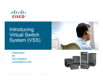
Virtual Switching Reduces Latency by 25%Traditional L2/L3SiVLAN XSiSiVLAN YVLAN XSiVLAN YVSS Simplifies Intra-Datacenter Traffic Pattern—Minimum Hop to Intra-Data Center Destination—Reduced Latency up to 25% and Simplifies traffic pattern—All links forwarding resulting in simple traffic pattern—Etherchannel on virtual Switch member enhanced to prefer local linkFor more Information on VSS : ion ID 2006 Cisco Systems, Inc. All rights reserved.Cisco Public30
High AvailabilityLink Failure RecoveryAccess Uplink Failure 200 msecPresentation ID 2006 Cisco Systems, Inc. All rights reserved.Cisco Public31
High AvailabilityLink Failure RecoveryRouted Uplink Failure 250 msecPresentation ID 2006 Cisco Systems, Inc. All rights reserved.Cisco Public32
High AvailabilityLink Failure RecoveryActive VS Failure 200 msecPresentation ID 2006 Cisco Systems, Inc. All rights reserved.Cisco Public33
High AvailabilityDual-Active DetectionIn a Virtual Switch Domain, one switch is elected as Active and the other is elected as Standbyduring bootup by VSLP. Since the VSL is always configured as a Port Channel, the possibilityof the entire VSL bundle going down is remote, however it is a possibility Switch 1 SupervisorVirtual Switch DomainSwitch 2 SupervisorVSLVS State : ActiveControl Plane: ActiveData Plane: ActiveVS State : StandbyControl Plane: StandbyData Plane: ActiveIt is always recommended to deploy the VSL with 2 or more links and distribute thoseinterfaces across multiple modules to ensure the greatest redundancyPresentation ID 2006 Cisco Systems, Inc. All rights reserved.Cisco Public34
High AvailabilityDual-Active DetectionIf the entire VSL bundle should happen to go down, the Virtual Switch Domain will enter a DualActive scenario where both switches transition to Active state and share the same networkconfiguration (IP addresses, MAC address, Router IDs, etc ) potentially causingcommunication problems through the network Switch 1 SupervisorVirtual Switch DomainSwitch 2 SupervisorVSLVS State : ActiveControl Plane: ActiveData Plane: ActiveVS State : ActiveControl Plane: ActiveData Plane: Active2 mechanisms have been implemented in the initial release to detect and recover from a DualActive scenario:1 Enhanced Port Aggregation Protocol (PAgP)2 Dual-Active Detection over IP-BFDPresentation ID 2006 Cisco Systems, Inc. All rights reserved.Cisco Public35
High AvailabilityDual-Active Detection - Enhanced PAgPEnhanced PAgP allows for new TLVs to be relayed from the individual Virtual Switches to aremote device that is EtherChanneled to the Virtual Switch Domain. During normal operationthe Virtual Switches will send the ID of the Active VS to the PAgP neighbor, and it will respondwith the same Active ID Switch 1Active: Switch 1Switch 2Active: Switch 1Switch 1Active: Switch 1Switch 2Active: Switch 2Should the VSL go down, the Standby switch will transition immediately to Active state andstart sending PAgP message with the new Active switch IDPresentation ID 2006 Cisco Systems, Inc. All rights reserved.Cisco Public36
High AvailabilityDual-Active Detection - Enhanced PAgPThe Enhnaced PAgP-capable neighbor will proceed to send the new Active Switch ID to allmember ports of the port channel that it received the new Active Switch ID on, including theprevious-active Virtual switch (Switch 1) Dual-Active!!Switch 1Active: Switch 2Switch 2Active: Switch 2Switch 1Switch 2Active: Switch 2On Switch 1, Upon reception of PAgP messages with the Active ID of Switch 2, it will be awarethat a Dual-Active scenario has occurred and will proceed to bring down all local interfaces*Presentation ID 2006 Cisco Systems, Inc. All rights reserved.Cisco Public37
High AvailabilityDual-Active Detection - IP-BFDDual-Active Detection with IP-BFD allows for the detection of a Dual-Active scenariosubsequent to the Standby RP becoming Active. This mechanism requires that a directheartbeat link be used to carry the IP-BFD frames from Switch 1 to Switch 2 VSLIP-BFD Heartbeat LinkSwitch 1Switch 2VSLBFDBFDIP-BFD Heartbeat LinkSwitch 1Switch 2The IP-BFD Heartbeat link may exist on any interface but must have an IP address assigned to iton a different networkPresentation ID 2006 Cisco Systems, Inc. All rights reserved.Cisco Public38
High AvailabilityDual-Active RecoveryUpon the restoration of one or more VSL interfaces, VSLP will detect this and will proceed toreload Switch 1 so that it may be able to re-negotiate Active/Standby role after bootup Switch 1Switch 2VSL Up! Reload Switch 1Switch 2VSLPVSLPAfter role has been resolved and SSO Hot Standby mode is possible, interfaces will be broughtup and traffic will resume back to 100% capacity Presentation ID 2006 Cisco Systems, Inc. All rights reserved.Cisco Public39
Presentation ID 2006 Cisco Systems, Inc. All rights reserved.Cisco Public40
Complex STP configuration and Management HSRP/VRRP- 3 IP address Manage Two Nodes and Config VSS Loop Free Topology with MEC Not Dependant on STP No HSRP/VRRP- 1 IP address Manage Single Node and Config Manage additional routing peers Manage reduced routing peers