Transcription
Environmental Health & SafetyOklahoma State UniversityADDRESSABLE FIRE ALARM SYSTEMSTANDARDEnvironmental Health and Safety University Health Services Suite 002 Stillwater, OK 74078 (405) 744-7241 www.ehs.okstate.eduReviewed and Revised October 2018
StatusContact(s)Implementation DateCommentsGerald Petre, EHSJune 2016Review and updateGerald Petre & Sharlie Doty,EHSSeptember/October 2018Review and update minorgrammatical errors
GeneralScopeThis standard outlines the requirements for an addressable fire alarm system for the Stillwater,Oklahoma campus. This standard shall be the basis of design for all campuses that fall under theOklahoma Agricultural and Mechanical Colleges with the approval of the University Fire Marshal.This standard addresses all materials, equipment and services necessary and required to design,install and test an addressable fire alarm system. Any material not specifically mentioned in thisstandard, or not shown on drawings, but required for proper performance and operation, shall befurnished and installed.The contractor shall design, furnish and install a fully code compliant (complete and ready foroperation) addressable fire alarm system; including control panel, software, schematics, detectors,manual pull stations, alarm devices, wiring, components, appurtenances and accessories, and allwiring and connections to devices furnished by others.Codes, Ordinances, and StandardsThe installation shall be made in accordance with the drawings, this standard, and the following: IFC, International Fire Code, current edition as recognized by Oklahoma state statute. NFPA 70, National Electric Code, current edition as recognized by Oklahoma statestatute. NFPA 72, National Fire Alarm Code, current edition as recognized by Oklahomastate statute. NFPA 101, Life Safety Code, current edition as recognized by Oklahoma state statute. ADA (Americans with Disabilities Act) All applicable state and local codes.All equipment and component parts shall be Underwriters Laboratories Listed and/or FactoryMutual Approved for use as a fire protective signaling system.Architects’ fire alarm drawings shall be used to indicate the area of protection. All symbols dictatethe area of protection—not the location of devices. Contractor shall be responsible for properlocation and coverage of all areas.Contractor’s proposal submission and shop plans shall be prepared by a manufacturer trained,NICET certified level 3 for fire alarm systems or a licensed fire protection engineer, and be anOklahoma licensed Commercial Fire Alarm Technician employed by a licensed commercial firealarm company.The contractor shall correct, at no added cost, all equipment that is installed outside the abovementioned codes. Authority Having Jurisdiction has the authority to accept or reject any installedequipment outside of these codes.
WorkmanshipAll work shall be performed by manufacturer trained and certified technicians licensed by theState of Oklahoma for fire alarm installation. All connections to fire alarm equipment shall besupervised by a NICET certified level 2 fire alarm systems technician, which shall be onsite whileconnection work is in progress.Contractor QualificationsThe contractor shall provide on-call twenty-four (24) hour, seven (7) days-a-week service. Servicepersonnel shall be available at any time for emergency service.The contractor shall be a stocking distributor of all equipment included in the system to allow forimmediate replacement of parts. In addition, the contractor shall have been actively engaged inthis type of work for a period of not less than ten (10) years and located within ninety (90) milesof the owner.The contractor shall be licensed by the state of Oklahoma to perform fire alarm work in the stateof Oklahoma.SubmittalsThe contractor shall submit three (3) complete sets of documentation to Long Range FacilitiesPlanning (LRFP) for review. Documentation shall indicate the type, size, rating, style, catalognumber, manufacturers' names, photos, and/or catalog data sheets for all items to ensurecompliance with this standard. Upon delivery to Environmental Health and Safety (EHS) fromLRFP, the review and return of submitted documentation to LRFP may take up to thirty (30)calendar days.Documentation shall consist of, but is not limited to, the following:1. List of data on the addressable fire alarm control panel: CPU (Central Processing Unit) Serial/parallel communication boards Loop interface boards Display interface board (LCD with operator keypad) Up-to-date software version Power supply2. List of data on the field initiating and notification devices: Monitor modules Control modules Addressable smoke detectors Addressable heat detectors Any other initiating devices (ex: duct detectors)
Manual pull stations shall be Fire Lite BG-8, Notifier BNG-1R or Simplex 4099-9021no gripSpeaker/strobesRemote power supply3. Voice evac: Audio voice message systemMulti-channel amplifiersSpeaker/strobesThe above-mentioned items are basic for a fire alarm system. Any other item that is required bycode and building configuration shall be added to the above list.This equipment shall be subject to the approval of the EHS and no equipment shall be orderedwithout this approval.Equipment and devices are to be shown on the contract drawings. Provide the following shopdrawings and lists. Complete one-line riser diagram showing all equipment and the size, type, and number ofall conductors. Large-scale drawing of the Fire Command Center room. Large-scale drawing of all field panels. Provide calculations to support the size of standby batteries submitted. A complete floor-by-floor fire alarm plan, showing devices, zone layout and wireinterconnections. A complete flow chart or outline of the programming that is going to be used for the firealarm panel.o Main subroutine: (general alarm, system disables)o Subroutines: (zones, buildings, wings, floors and large areas)o Sub-subroutines: (auditoriums, large classrooms, and any rooms that have morethan three (3) initiating devices)
System Description and FunctionThe addressable automatic fire alarm system shall consist of a main control panel, remote powersupply panels, remote control panels, detection devices, manual stations, HVAC fan relay controlmodules, and magnetically-held fire door relay control modules that are wired in accordance withthe schedule on the drawings and shall function as specified herein. The system shall be capable ofbeing expanded at any time.The system shall be capable of operating both addressable and non-addressable thermal andphotoelectric detecting devices, manual stations, sprinkler supervisory switches and water-flowswitches. Supervisory switches shall be set up for supervisory (trouble) causing only.The system shall function as follows when any smoke detector, heat detector, duct detector,manual pull station or water flow switch operates: Sound the required audible notification devices as shown on the drawings.o Activate the EVAC message. Illuminate all visual notification devices as shown on the drawings. Automatically notify the fire department via the OSU central reporting station. ContactFacilities Management, MEP Life Safety group for account number, phone numbers or anyother required information and programming. Display the device(s) and location of the device(s) in alarm and in trouble on the LCDDisplay and interactive display system. Conventional zones (monitor modules) are to display the area of protection. Light an indicating lamp on the device initiating the alarm. Shut down the HVAC system and operate dampers as shown on the drawings. Close all magnetically-held fire doors as shown on the drawings. Operate smoke removal systems, if required for that initiating device. Activate emergency elevator operation, if required for that initiating device. Activate natural gas shutoff (only if alarm exists in the area of natural gas).NOTE: There shall be no limit, other than the maximum system capacity, as to the numberof addressable devices that may be in alarm simultaneously.The system shall function as follows when a building, zone, floor, and/or device are disabled.When the building is disabled: All notification devices in that building shall not be activated. All AHU and fire doors in that building shall not be activated. Transmission of fire alarm signal shall not be activated.When the zone is disabled: All notification devices within that zone shall not be activated.
All AHU and fire doors within that zone shall not be activated.Transmission of fire alarm signal shall not be activated.All other areas outside the disabled zone shall activate the fire alarm system and itsprogrammed functions.When the floor is disabled: All notification devices on that floor shall not be activated. All AHU and fire doors on that floor shall not be activated. Transmission of fire alarm signal shall not be activated. All other areas outside the disabled floor shall activate the fire alarm system and itsprogrammed functions.When the sprinkler system alarm circuit is disabled: All notification devices shall not be activated.All AHU and fire doors shall not be activated.Transmission of fire alarm signal shall not be activated.All other parts of the fire alarm system shall activate the fire alarm system and itsprogrammed function.
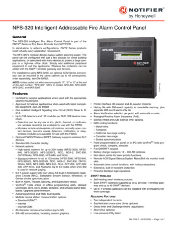
ProductsGeneralAll materials, equipment, accessories, devices and other facilities and appurtenances covered bythese standards or noted on the contract drawings and on the contractor’s approved workingdrawings and installations shall be up to date, new, best suited for its intended use and shallconform to applicable and recognized standards for their use. All equipment shall be the standardcataloged products of a single manufacturer for the system being installed with the exception ofthe manual stations (Notifier Model BNG-1R, Fire Lite BG-8 or Simplex 4099-9021 no grip), andthe Emergency Notification Interior System Interface (ISI) (RTU-ISI) . . . NO SUBSTITUTES.Since this system is to be part of an overall existing campus fire alarm system, NO FIRE ALARMCONTROL PANEL OTHER THAN A SIMPLEX GRINNELL 4100ES, or NOTIFIER NFS2-3030 shall beaccepted for the equipment specified in this section.Control EquipmentFire Alarm Control Panel (FACP)The FACP shall provide power, annunciation, supervision and control for the detection and alarmsystem. The FACP shall be modular in construction and contain all necessary integrated modulesto operate in accordance with this section and the applicable drawings.The system shall provide fail-safe operation, i.e. incoming alarms shall automatically override allother modes of operation, and the panel shall automatically return to normal operating mode fromany operator-initiated mode.Dynamic supervision of system electronics, wiring, and detection devices shall be provided by thecontrol system. Failure of system hardware or wiring shall be indicated by type and location onthe alphanumeric annunciator. Ground fault detection shall be provided for all initiating andaudible circuits. Lamp test capability shall be provided for all visual panel indicators.A service mode shall permit the arming and disarming of individual detection devices and a groupof detection devices (zones). Status of these devices shall be displayed upon command from thecontrol panel. If any change in status degrades system operation as configured, a trouble conditionshall be reported and remain until system operation again meets configured status.Panel shall be capable and programmed for one button operation for the following bypasses:speaker/strobe, AHU, elevator and sprinkler.Owner shall be capable of entering the FACP programming software to make changes whenneeded.No audible signal shall be heard from the fire alarm control panel upon receiving a trouble signal.Fire Alarm Control Panel shall be installed in a room or location that has been approved by theUniversity Fire Marshal.
Power Supply PanelsFire alarm control panel powerThe primary power supply shall operate from 120 volts AC. Power shall originate from either anemergency panel located at the main distribution panel or an emergency generator panel. 120 volt AC power shall be dedicated to the fire alarm system panels only. Powers supplypanel location will be annotated inside control panel. Breaker shall be marked in red, labeled as Fire Alarm and locked to the on position.The secondary power supply shall consist of batteries and a charger, enabling automatic switchingto battery power in the event of loss of power from the primary supply and switching back to theprimary power supply when it is restored. An automatic tapering charge battery charger capableof fully recharging the batteries in twelve (12) hours shall be supplied to maintain the batteries.Supervision of battery connections, battery fuse or breaker, and battery condition shall beprovided and shall produce a trouble signal when any condition occurs that would preventoperation of the secondary power supply.Remote Power Supply (Notification and Auxiliary)There shall be at least four (4) 24-volt outputs per remote power supply. Each output shall beused for audio, visual, and auxiliary (AHU or fire doors).Shall be activated by the fire alarm control panel.Shall operate from 120-volts AC. (Receive AC power from the same power supply/ panel as theFACP AC power).There shall be a second source of power that consists of batteries and charger enabling automaticswitching to battery power in the event of loss of power from the primary supply and switchingback to the primary power supply when it is restored. An automatic tapering charge, batterycharger capable of fully recharging the batteries in twelve (12) hours shall be supplied to maintainthe batteries.There shall be supervision of the following: Main power source. Battery and charger. All output circuits. Ground faults.Note: The supervisory signal shall be sent to the Fire Alarm Control Panel. There shall beproper annunciation of the remote power supply panels.Remote power supply panels shall be installed no more than six feet (6’) above the floor,measured from the top of the remote power supply panel and easily accessible. Location shall beapproved by EHS.Locate remote power supply in the building area in which it is being used.
IndicatorsThe FACP shall provide an alphanumeric display, which shall provide a user definable messageassociated with each heat, smoke, control module, monitor module, remote power supply or zone.Normal conditions shall be indicated by a green light, trouble conditions by an amber light, andfire conditions by a red light. Trouble indicating lights shall automatically reset when troubleconditions are cleared. Fire indicating lights must remain lit at the control panel until manuallyreset.Remote annunciators shall display the alarm and trouble message on LCD alphanumeric display.The annunciator shall also be capable of silencing the alarm signal. The annunciator shall beplaced in a cabinet with a window door and locked. Remote annunciator shall have the capability of selective zone paging.Remote annunciator(s) shall be located at a main entrance on the first floor of a building/wing,other annunciators may be required, dependent on building configuration. EHS shall give theapproval of the location.Signal Initiation CircuitsIndividual input and output device addressability shall be performed on the same pair of wires.Wiring shall be class B. No special wiring sequence shall be required on addressable devicecircuits. An unlimited number of wiring branches shall be permitted with no loss of supervision.All wiring branch origination points shall be indicated on the “as-built” drawings. Addressabledetection devices shall be individually identified by the system using user-defined messages. Thesystem shall be capable of reading the sensitivity of remote addressable ionization andphotoelectric detection devices.All smoke detectors shall provide alarm verification via the control panel.All control function of the smoke detectors shall be provided via the control panel, and softwarecontrol.All smoke detector sensitivities shall be controlled by the FACP. System shall be capable ofshowing all smoke detector values.There shall be twenty percent (20%) of device space available for each signal initiation circuit forfuture expansion.Each floor shall have its own signal initiation circuit installed.Notification CircuitsAudible notification circuitsAt least two (2) class B supervised, general alarm, audible notification output circuits shall beprovided. It shall be possible to disarm these output circuits from the control panel without thedisconnection of wiring. Disarming these output circuits shall cause a trouble signal to begenerated and shall also indicate, by user-defined message on the alphanumeric display, the causeof the trouble signal.
The disarming of audible notification devices shall be set for building disarm, floor disarm, andzone disarm.These output circuits can be used to activate the remote power supply panels.Each floor shall have its own audible notification circuit installedVoice evacuation (required)Emergency voice/alarm communications service shall be provided by a system with automatic ormanual voice capability that is installed to provide voice instructions to the building occupants.In response to an initiating signal indicating a fire emergency, the system shall automaticallytransmit a message (that has been recorded by the user) either immediately or after a delayacceptable to the authority having jurisdiction, consisting of the following: A tone of a “whooping” sound of three (3) seconds to ten (10) seconds duration followedby a message. An example of a message may be: “MAY I HAVE YOUR ATTENTION PLEASE?MAY I HAVE YOUR ATTENTION PLEASE? THERE HAS BEEN A FIRE EMERGENCYREPORTED IN THE BUILDING, PLEASE GO TO THE NEAREST EXIT AND LEAVE THEBUILDING. DO NOT USE THE ELEVATORS.” Then repeat the tone and message untilsilenced by the user.Failure of the message described above, where used, shall sound the evacuation signal (whoopingsound) automatically. Provisions for manual initiation of voice instructions or evacuation signalgeneration shall be provided.Live voice instructions shall override all previously initiated signals on that channel and shall havepriority over any subsequent automatically initiated signals on that channel.System shall be capable of multi-channel operation.All other requirements by code shall comply with NFPA 72.Speakers shall be set up for building, wing, floor, and zone notification. Shall be capable ofselecting, activating or deactivating the speakers by building, wing, floor, or zone individually.Visual notification circuitsAt least one (1) supervised general alarm visual output circuit shall be provided. It shall bepossible to disarm this output circuit from the control panel without the disconnection of wiring.Disarming this output circuit shall cause a trouble signal to be generated and shall also indicatethe cause of the trouble signal by a user-defined message on the alphanumeric display.The disarming of the visual notification devices shall be capable of building, floor, or zones disarm.Do not overload the fire alarm control panel power supply. There shall be a separate power supplyor output circuit from the remote power supply for the visual notification devices. This supply ofpower shall have supervision capabilities and shall be monitored by the fire alarm control panel.Each floor shall have its own visual notification circuit installed.Central station notificationAutomatically notify the fire department via the OSU central reporting station. Contact FacilitiesManagement, MEP Life Safety group for more information.
Emergency notification Interior System Interface (ISI)The ISI controller shall be an American Signal Corporation (ASC) Model # RTU-ISI, and shall beobtained through SimplexGrinnell of Tulsa, Oklahoma. NO SUBSTITUTIONS SHALL BE ALLOWED.The ISI controller must be capable of interfacing with the SimplexGrinnell 4100ES or NotifierNFS2-3030, fire alarm panel allowing activation/control all speaker circuits. This will be achievedthrough relay contact closure and a 1-volt peak to peak line level audio Input. This relay contactmust have a minimum rating of 5 amperes at 240-volts AC. Controller must operate with an inputpower of either 120 or 240-volts AC, field selectable. Additional capability must be available in thecontroller to generate signals with special timing requirements. A CANCEL signal must be availableto immediately halt an active signal.The controller will be contained in a weatherproof enclosure suitable for outdoor environments.All metallic surfaces will be painted or otherwise protected to retard corrosion.The controller should use state-of-the-art electronics in its design. All controller information shallbe contained in EEPROM memory, and shall be field changeable for programming changes. Amodular design shall be employed to aid in servicing requirements.The controller will use an FSK-FM (Frequency Shift Keyed Frequency Modulated) method for datacommunication. This FSK-FM data stream will have additional security features available toprevent false ISI activation from “hackers.” The data packet format must be compatible with thesystem currently in operation at Oklahoma State University. The use of two-tone or DTMFcommunications for control are not acceptable.Radio communications must be compatible with a radio frequency of the existing radio signalingprotocol currently in use at Oklahoma State University. The ISI controller shall have circuitry,which will wait for channel availability before communications are initiated.The ISI controller will provide status monitoring to the central activation sites. The controller willprovide status change indications for controller door open (tampering), AC power fail, and lowbattery voltage. These status changes will be reported immediately when the condition occurs.Each controller will have a backup battery to operate the electronics and radio transceiver in caseof AC mains failure. A built-in charger system will keep the battery at full charge during normaloperation.The controller will have capability for local activation. A total of six (6) functions must be availablefor use, along with a cancel function. Each function button must be programmable via software toactivate any standard signal or custom signal. Local operation of ISI will be reported to the centralactivation sites.Each controller will be identified to the master system by use of a three (3) character address.Each ISI address will be assigned by the manufacturer in accordance to the existing schematicdeveloped for Oklahoma State University in conjunction with SimplexGrinnell managementaccording to its quadrant numbering plan.Auxiliary Output Circuits and DevicesGeneralIndividual input and output device addressability shall be performed on the same pair of wires.Addressable relay control devices shall be individually and collectively (group) controlled within
the programming. It shall be possible to disarm these addressable relay control devices from thecontrol panel without the disconnection of wiring. Disarming any of these addressable relaycontrol devices shall cause a trouble signal to be generated and shall also indicate by user-definedmessage on the alphanumeric display the group disarmed. It shall be possible to activate theseaddressable relay control devices individually from the control panel.If auxiliary devices require 24-volt DC power, this power will be supplied by the FACP or the useof a 24-volt output from the remote power supply.Air handling unit shutdownHVAC fan shutdown shall be achieved by the use of addressable relay control modules.The addressable relay control module shall be designated for HVAC control only. No otherequipment shall be controlled by this device.Smoke/fire door release and access control doorsMagnetically-held fire door release shall be achieved by the use of addressable relay controlmodules.Access control doors shall unlock by addressable relay control modules.The addressable relay control module shall be designated for fire door control only. No otherequipment shall be controlled by this device.Smoke removal system controlSmoke removal system actuation (if required) shall be achieved by the use of addressable relaycontrol modules. The initiating devices controlling this addressable relay control module shall beas indicated on the drawings.The addressable relay control module shall be designated for smoke removal control only. Noother equipment shall be controlled by this device.The capability of remote operation of the smoke removal system shall be installed next to theFACP.Fire and smoke damper controlFire and smoke damper control shall be achieved by the use of addressable relay control modules.The initiating devices controlling this addressable relay control module shall be as indicated onthe drawings.The addressable relay control module shall be designated for fire and smoke damper control only.No other equipment shall be controlled by this device.Emergency elevator controlEmergency elevator control shall be achieved by the use of addressable relay control modules. Theinitiating devices controlling this addressable relay control module shall be as indicated on thedrawings.The addressable relay control module shall be designated for elevator control only. No otherequipment shall be controlled by this device.
Natural gas shut offThe natural gas shut off (if required) shall shut the gas off in an area where natural gas is used.Example- Kitchen: It shall be achieved by the use of addressable relay control modules.The addressable relay control module shall be designated for natural gas shut off control only. Noother equipment shall be controlled by this device.Cabinet(s)The FACP cabinet shall be of the surface, semi-flush or flush mount type and shall compactly houseall solid state cards, indicating lamps, switches, power supply panels, batteries, etc. for the system.The power supply and batteries will be mounted in the FACP cabinet. All lamps and controls shallbe behind a hinged locked door ("dead front") with glass or plastic vision panel(s) and lock.DevicesAC PowerFACPDedicated branch circuit shall be used for the FACP power supply and no other non-fire alarmsystems or components. There shall be a surge protector installed in the FACP. Location of powersupply breaker will be annotated inside FACP.Remote power supplyDedicated branch circuit shall be used for the remote power supply and no other non-fire alarmsystems or components. There shall be a surge protector installed for the remote power supply.Location of power supply breaker will be annotated inside remote power supply.BatteriesApproved gel cell-type batteries shall be provided as an emergency power source to power thesystem (FACP and remote power supply panels) in the event of power failure. Batteries shall be ofsufficient capacity to power the system under trouble and standby conditions for twenty-four (24)hours and to operate all notification appliances for at least five (5) minutes to the end of thisperiod. Batteries shall be seven (7) amp hours capacity as a minimum.Locks and KeysAll locks shall be keyed to one of the following 17021, 17003 or “B” key. All locks that do not operate with one of the listed keys shall be replaced with a lock thatdoes work. With the exception of EHS specified pull boxes, all fire alarm devices associated with thefire alarm panel, shall be keyed the same as the fire alarm panel.
Close security of all keys to the alarm system is a requirement of this standard. The equipmentsupplier shall have the responsibility of retaining all except two (2) keys that are to be checked outto the contractor for construction and tests. (Additional keys may be obtained by the contractorfrom the Key Department if needed.) The equipment supplier shall transfer all keys to the KeyDepartment when the equipment is delivered to the contractor. The contractor shall return allkeys to the Key Department at the completion of the job.Manual Fire Alarm StationsTo maintain uniformity on the campus, THERE SHALL BE NO SUBSTITUTES for NOTIFIER MODELBNG-1R, FIRE LITE BG-8 or SIMPLEX 4099-9021 NO GRIP. The lock shall be keyed to the, 17021 or17003 key lock for test purposes. Manual fire alarm stations shall be provided with addressablemonitor modules.Notification AppliancesSpeaker/strobes combination, speaker only, and strobe only. Audio/visual notification appliances shall be speaker-strobe designed for flush, wall orceiling mounting. All necessary adapters to achieve the mounting style specified shall befurnished. All appliances shall be red, white or black in color, with white strobe lamp.The sound level of the audio devices shall meet all current standards for audibility andintelligibility designed to endure Common Intelligibility Standard (CIS) rating of .7 orsound transmission index of .5.All devices shall be ceiling mounted. If the device cannot be ceiling mounted, the walllocation shall be approved by the University Architect and the University Fire Marshal.The tops of wall mounted audio devices shall be located no less than ninety inches (90”)above the finished floor. If the required height cannot be achieved, they shall be located noless than six inches (6”) below the finished ceiling.The location of wall mounted audio/visual and visual devices shall have their bottoms atheights above the finished floor of not less than eighty inches (80”) and no greater thanninety-six inches (96”).EVAC speakers and EVAC speakers/strobe combinationSpeakers and their enclosures shall be listed for voice/alarm signaling service and installed inaccordance with (1) of this section and NFPA 72.Smoke DetectorsSmo
The addressable automatic fire alarm system shall consist of a main control panel, remote power supply panels, remote control panels, detection devices, manual stations, HVAC fan relay control modules, and magnetically-held fire door relay control modules that are wired in accordance with
