Transcription
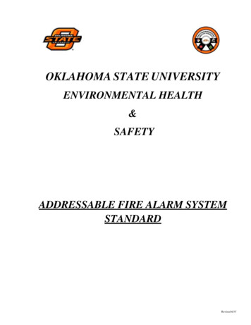
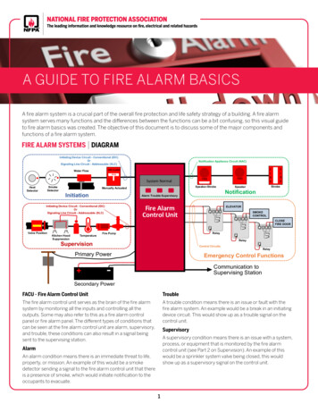
A GUIDE TO FIRE ALARM BASICSA fire alarm system is a crucial part of the overall fire protection and life safety strategy of a building. A fire alarmsystem serves many functions and the differences between the functions can be a bit confusing, so this visual guideto fire alarm basics was created. The objective of this document is to discuss some of the major components andfunctions of a fire alarm system.FIRE ALARM SYSTEMS DIAGRAMInitiating Device Circuit - Conventional (IDC)OrSignaling Line Circuit - Addressable (SLC)Notification Appliance Circuit (NAC)FIREFIRE ALARMWater FlowPULLSystem NormalSmokeDetectorHeatDetectorFire AlarmControl UnitKitchen OLNO-NCCNOCLOSEFIRE DOORRelayControl CircuitsPrimary Power ELEVATOR- Fire PumpStrobeSpeakerNotificationAlarm Trouble SupervisoryInitiating Device Circuit - Conventional (IDC)OrSignaling Line Circuit - Addressable (SLC)Valve PositionSpeaker-StrobeManually ActuatedInitiationFIREFIREFIRE NCCNORelay RelayEmergency Control FunctionsCommunication toSupervising Station-Secondary PowerFACU - Fire Alarm Control UnitTroubleThe fire alarm control unit serves as the brain of the fire alarmsystem by monitoring all the inputs and controlling all theoutputs. Some may also refer to this as a fire alarm controlpanel or fire alarm panel. The different types of conditions thatcan be seen at the fire alarm control unit are alarm, supervisory,and trouble, these conditions can also result in a signal beingsent to the supervising station.A trouble condition means there is an issue or fault with thefire alarm system. An example would be a break in an initiatingdevice circuit. This would show up as a trouble signal on thecontrol unit.SupervisoryA supervisory condition means there is an issue with a system,process, or equipment that is monitored by the fire alarmcontrol unit (see Part 2 on Supervision). An example of thiswould be a sprinkler system valve being closed, this wouldshow up as a supervisory signal on the control unit.AlarmAn alarm condition means there is an immediate threat to life,property, or mission. An example of this would be a smokedetector sending a signal to the fire alarm control unit that thereis a presence of smoke, which would initiate notification to theoccupants to evacuate.1
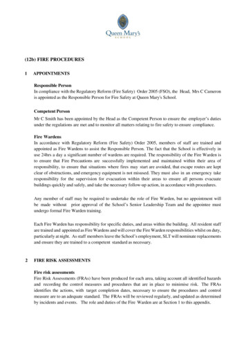
InitiationPart 2 SupervisionPart 3 Power SupplyPart 4 NotificationPart 5 Emergency Control FunctionsPart 6 Off-Premises Signaling andAddressable devices are eitherSignaling Line CircuitSignaling Line Circuitinitiating devices or control/notification appliances that areFcapable of communicating aAunique identification numberCor address to a control unitUvia a signaling line circuit.This identification consistsof a binary string of 1s and0s that indicate the addressor location of that device on the circuit. When the FACU polls aninitiating device, the initiating device responds with its status(normal, alarm, etc.) and address. The device address allows forthe location of the detector to be identified at the FACU. Whenone initiating device is activated on a signaling line circuit, theFACU is still able to poll the other devices unlike a conventionalinitiating device circuit.Notification Appliance Circuit (NAC)Part 1Supervising StationsPART 1InitiationInitiating Device Circuit - Conventional (IDC)OrSignaling Line Circuit - Addressable (SLC)Additionally, some addressable initiating devices are able toalso transmit to the FACU a range of values of smoke density,FIRE andFIRE pressure changes,temperaturevariation, water level, waterSystem Normalother variables. And then the control unit software determines theSpeaker-StrobeSpeakerset points for initiation of an alarm, supervisory, or trouble signal.NotificationThesetypesSupervisoryof initiating device circuits are known as analogAlarm Troubleaddressable as they are able to tell the FACU their address andtheir value.ELEVATORFIRE ALARMWater FlowPULLHeatDetectorSmokeDetectorManually ActuatedInitiationFire AlarmControl UnitInitiating Device Circuit - Conventional (IDC)The main function of the initiationOr portion of a fire alarm systemLine Circuit - Addressable (SLC)is to report theSignalingstatus ofa protected space or the existenceof a fire. The components include all devices and circuits thatsend a signal to a fire alarm control unit (FACU) such as heatdetectors, smoke detectors, carbon monoxide detectors, waterValve PositionPumpflow switches, manuallyactuated Temperaturedevices, and Firepressureswitches.Kitchen HoodSuppressionDepending on the system, the signal from an initiating deviceSupervisioncan create an alarm conditionor a supervisory condition. Basedon the type of detectors and FACU, the signals can be sent overPoweran initiating device circuit (IDC)Primaryfor conventionalsystems, or asignaling line circuit (SLC) for addressable systems. IonizationSmoke DetectorIonization smoke detectorsIonizationSmokeDetector SMOKECONTROLutilize a small amount ofSmokeClean Airradioactive material to ionize11air molecules into positively 2002Relayand negatively charged molecules that create aRelaysmall electric current. The Control Circuits Relayintroduction of smoke into - - that ionized air will reduceEmergency Control Functhe amount of current andRadioactive Material Radioactive Materialcause an alarm signal.NCCNONCCNONCCommunication to-Conventional initiating uitare typically detectors that usea switch contact to short bothFPowersides of the initiating device SecondaryACcircuit together. By doing so,UIDC- Normal Conditionthe initiating device causesan increase in current flowingFthrough the circuit, which theAFACU interprets as an alarmCUsignal. Once one device shortsIDC- Alarm Conditionthe circuit, no other device onthat circuit or “zone” can senda signal. Because of this, any device on the circuit or zone will putthe entire zone into an alarm state. Zones are typically designedto enable someone to easily identify an area where the alarm islocated, for example, in a school you may have a gymnasium zonecircuit and an auditorium zone circuit that each contain multipledevices.SupervisingPhotoelectric smoke detectors utilize a lightsource and a Stationphotosensitive cell. When smoke enters the chamber, lightscatters and is picked up by the photosensitive cell, causing analarm signal.Photoelectric Smoke DetectorPhotoelectric Smoke DetectorNormal StateAlarm StateLight SourcePhotoelectric Cell2Light SourcePhotoelectric CellCNO
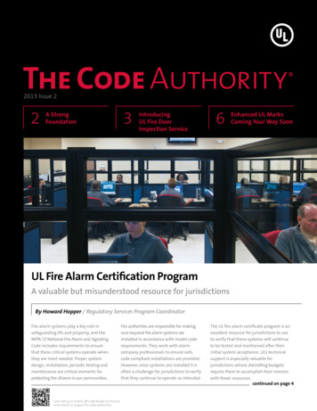
An analog addressable heat detector utilizes a thermistorelement to constantly monitor the temperature. The responsecriteria, which can be a temperature above a specified level, ora specific rate of rise in the temperature, is programmed at theAnalog Addressable Heat DetectorFACU.A beam smoke detector is like a photoelectric detector, exceptit is designed to cover a large area. A transmitter and receiver orreflector are placed to create a light beam across a space, whenthe amount of light being received by the receiver or reflected tothe transmitter falls below a certain percentage, an alarm signalis sent.Beam Smoke DetectorTransmitterAnalog AddressableHeat DetectorReceiver orreflectorThermistorThere are many different types of carbon monoxide (CO)detectors. One example of a CO detector is a Colorimetricdetector. Like a photoelectric smoke detector, this detectorcontains a light source and a photocell that are constantlymeasuring for light being reflected from a chemical detector.In the presence of carbon monoxide, the chemical detector willchange to a black color and light will no longer be reflected to thephotocell, which will resultin an alarmsignal. DetectorCarbonMonoxideBeam Smoke Detector6A non-restorable fixed temperature heat detector utilizessolder that holds up a plunger. The solder melts at a specifictemperature and causes the plunger to drop, which shorts theFixed Temperature Heat Detectorcontacts and causes an alarm signal.Non-RestorableNormal StateAlarm StateLight SourceFixed TemperatureHeat DetectorNon-RestorableCarbon MonoxideDetectorChemicalDetectorPhotocellSometimes called manual fire boxes, pull stations, or call points,manually actuated initiating devices initiate an alarm signal whenthere is an input from a person, such as pulling a lever or pushinga button. These can require multiple actions to initiate such aslifting a cover or breakingglass priorto actuatingthe device.ManuallyActuatedInitiatingDeviceA restorable fixed temperature heat detector utilizes two metalsthat have different thermal expansion coefficients. At a specifictemperature, these metals will bend and cause the plunger toshort the contacts, whichcausesan alarm condition.When theFixedTemperatureHeat Detectormetal cools it will bend back in the other direction and restoreRestorableitself.FIRE ALARMManually ActuatedInitiating DeviceFixedTemperatureHeat DetectorRestorablePULL DOWNFIRE ALARMBREAK GLASSFlow switches are installed inside the piping of a sprinkler systemand have a vane that moves with the flow of water. When waterbegins to flow within the pipe, the vane operates a switch thatinitiates an alarm.Vane Waterflow SwitchA rate-of-rise detector utilizes an air chamber and a diaphragm.When a fire causes the air in the chamber to expand faster than itcan escape out the vent,Rate-of-Rise HeatDetectorthe increased pressureRate-of-RiseHeatDetectorforces the diaphragm toclose the contacts andinitiate an alarm signal.This rate-of-rise detectoralso contains a fixedtemperature plungerthat will operate if thetemperature exceeds thedetermined temperature.Vane Waterflow SwitchVaneVane Waterflow SwitchInstalled in PipePhoto courtesy Tara Timmons3
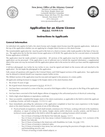
Pressure switches are installed onPressure SwitchAir Pressuresprinkler systems to monitor for achange in water pressure. A signalInitiating Device Circuit - Conventional (IDC)will be sent to the FACUwhen there OrLine Circuit - Addressable (SLC)is an increase in water Signalingpressure,which means that water is flowingFIRE ALARMWater FlowPULLthough the sprinkler alarm tiation2019Manually Actuateda unique identification numberSignaling Line CircuitSignaling Line Circuitor address to a control unitvia a signaling line circuit.FThis identification consistsNotification Appliance Circuit (NAC)Aof a binary string of 1s andC0s that indicate the addressUor location of that device onFIREFIREtheSystemcircuit. NormalWhen the FACUpolls a supervisory device,Speaker-StrobeSpeakerthe device responds withNotificationitsstatus(normal,supervisory, etc.) and address. The deviceAlarmTroubleSupervisoryaddress allows for the location to be identified at the FACU. Whenone supervisory device is activated on a signaling ELEVATORline circuit, theFACU is still able to poll the other devices unlike a conventional SMOKECONTROLinitiating device circuit.Additionally, some addressable supervisory devices are also ableto transmit to the FACU a range of values such as temperature,water level, pressure, and other variables, Relayand then the control unit software determines the set points for initiation of a Relaysupervisory signal. These types of Controlsupervisory Circuits devices are knownRelayas analog addressable as they are able to tell the FACU theiraddress and their value.Emergency Control FuncFire AlarmControl UnitInitiating Device Circuit - Conventional (IDC)OrSignaling Line Circuit - Addressable (SLC)NCCNONCCNONCValve PositionKitchen HoodSuppressionTemperatureFire PumpSupervisionPrimary PowerIt is common and often required to utilize a fire alarm system tomonitor the condition of other systems, processes, or equipmentthat are related to the building’s fire and life safety or othersystems that the owner would like to monitor. Supervision caninclude but is not limited to valves on fire protection systems,other fire protection systems suchas kitchen Powerhood suppressionSecondarysystems, valve room or storageInitiating Device Circuittank temperatures, and fireInitiating Device Circuitpump condition. Issues withthese systems would provide aFAsignal to the fire alarm controlCunit via an initiating deviceUIDC- Normal Conditioncircuit (IDC) for conventionalsystems, or a signaling lineFcircuit (SLC) for addressableACsystems and would create aUIDC- Alarm Conditionsupervisory condition at the firealarm control unit (FACU). ValvePositionValve PositionValves that can shut offCommunication tothe water supply for a fireSupervising Stationsuppression system suchas a sprinkler system arerequired to be supervisedto ensure that they are notclosed while the system is inservice. One way of supervising these valves is the use of the firealarm system. This is done by installing a switch, which will senddistinct signals to indicate that either a control valve has beenmoved from its normal position (typically meaning that the valvehas been shut) or that the control valve has been restored back toits normal d fire suppression systemsare required to be maintained above atemperature of 4O F (4 C) where thesystem piping is filled with water. OneVALVE ROOM TEMP - 01way to ensure that these systems are notsubject to freezing temperatures is toutilize the fire alarm system. This is done byplacing temperature devices that can senda signal to the fire alarm control unit whenthe temperature in a space has dropped below 4O F (4 C) and forwhen the temperature has been restored to a temperature above4O F (4 C).Conventional supervisory devices are devices that are used onan initiating device circuit and use a switch contact to short bothsides of the device circuit together. By doing so, the device causesan increase in current flowing through the circuit, which theFACU interprets as a supervisory signal. Once one device shortsthe circuit, no other device on that circuit or “zone” can senda signal. Because of this, any device on the circuit or zone willput the entire zone into a supervisory state. Zones are typicallydesigned to enable someone to easily identify an area wherethe supervisory is located, for example, you may have all of thevalve supervisory switches for one system on its own zone so thesupervisory comes up as “supervisory wet pipe system 1.”If a building has a fire suppression system other than a sprinklersystem such as a kitchen hood suppression system, or an inertgas system, it may be required to be monitored by the fire alarmsystem. Based on the system type and the building occupancy,Addressable supervisory devices are capable of communicating4CN
some of the signals may appear on the fire alarm control unit assupply, as well as some calculations that are necessary to ensurea supervisory signal, which indicates that there is an issue withthat the fire alarm system is provided with sufficient backupthe suppression system that mustpower.Other Suppressionbe addressed. The other suppressionSystems Systems There are a few different options out there when it comes tosystems may be connected directly Other Suppressionproviding a reliable power source. They include providing anto the building fire alarm control unit,additional power source in addition to the primary power such asor the other suppression system isbatteries or an emergency generator so there is backup powercontrolled by its own fire alarm controlif primary power is lost or providing power through a singleunit (known as a releasing panel) thatsource such as a stored-energy emergency power supply systemis then connected to the buildings(SEPSS).main fire alarm control unit.Power Supply OptionsFire Alarm Power Supply OptionsSome water-based fire suppression systems such as a dry pipeor preaction sprinkler system may require the use of pressurizedair or nitrogen within the system piping. In some cases, thepressure within the piping is required to be supervised by thefire alarm system. This is done using pressure transducers orpressure switches that are connected to the fire alarm controlunit. A supervisory condition may then be created if the pressurein the piping is too high, or too low.If the building has a fire pumpthat supplies a water-based firesuppression system such as asprinkler system or a standpipesystem, the fire alarm controlunit is connected to the fire pumpcontroller to monitor for thefollowing conditions:Two Power Supply SourcesPrimary (AC) Power BatteriesPrimary (AC) Power Batteries GeneratorPrimary (AC) Power Stored-EnergyEmergency PowerSupply System (SEPSS)Primary power to the fire alarm system can be provided bythe electric utility, an engine-driven generator (this is not astandby generator, however it is a site generator meeting therequirements in NFPA 72 , National Fire Alarm and SignalingCode , and SEPSS, or a cogeneration system.FireFirePumpPumpPrimary PowerPRIMARY POWER Pump or engine running Controller main switch off normal Trouble with the controller or engine Main power to electric fire pump disconnected Phase reversal on electric fire pump Loss of phase on electric fire pumpElectric UtilityEngine-Driven GeneratorCogeneration SystemBatteries are a common way to provide a secondary powersupply, the most common type of battery is a valve-regulatedlead-acid battery and they are typically located within the firealarm control unit enclosure, or in a separate battery box locatednear the fire alarm control unit. Batteries need to be sized sothat they can provide powerBatteriesBatteriesto the entire fire alarm systemfor 24 hours in standby and5 minutes in alarm, if thesystem is an emergency voicealarm communication system(EVACS), then the batteriesneed to provide capacity for15 minutes in alarm in addition to the 24 hours in standby. Theadditional time is required to allow for a longer evacuation timeas buildings with an EVACS typically utilize a partial evacuationthat would require constant communication with the occupantsduring the evacuation.For more information on fire pumps take a look at this blog.Water TankIf a water tank is used to supply a waterWater Tankbased fire suppression system, the waterlevel in the tank and the temperature ofthe water may need to be monitored. Thisis done by installing water level sensorswithin the tank that can send a signal ifthe water level drops by a specified level,and the installation of water temperaturesensors that can send signals if the temperature drops below4O F (4 C) and for when the temperature has been restored to atemperature above 4O F (4 C).PART 3Single Power Supply SourcePower SupplyAnother common way of providing a secondary power supplyfor a fire alarm system is the use of an emergency generatordesigned, installed, and maintained in accordance with NFPA110, Standard for Emergency and Standby Power Systems, whichIt is important for a fire alarm system to be provided with reliablepower so it can operate during any emergency. There are a fewdifferent options when it comes to choosing a reliable power5
1. First the total system standby current and the total systemalarm current is calculated. This is done by multiplyingthe standby current and alarm current for each piece ofequipment by the total quantity of each piece of equipmentand adding them together, the result is the total ampsrequired in standby and alarm. Both the standby currentand the alarm current for equipment can be found from themanufacturer in the data sheet.provides power to the fire alarm system through an automatictransfer switch. If using an emergency generator, you are stillrequired to provide batteries as well just in case there is anissue with getting ency generatorstarted. These batterieshowever, only need toprovide a capacity for4 hours instead of the24 hours in standby.2. Next total standby capacity is required by multiplying the totalsystem standby current by the required 24 hours to achievethe required standby capacity in amp-hrs. The same isdone with the alarm capacity, however, instead of 24 hours,the current is multiplied by either 5 minutes (0.083 hours) or15 minutes (.25 hours) to achieve the required alarm capacityin amp-hrs.Instead of providing two separate power supplies, you arepermitted to provide power via a SEPSS otherwise known as anenergy storage system (ESS) or an uninterruptiblepower supply (UPS). The SEPSS must be configured inaccordance with NFPA 111 and provide 24 hours of backupbattery. The SEPSS is alsofed via a compliant primaryStored-Energy EmergencyEmergencyStored-Energypower supply such asPowerSupplySystemPower Supply System(SEPSS)(SEPSS)utility power or an on sitegenerator.3. Finally, both the standby capacity and the alarm capacity isadded together and a 25% safety factor is applied to arrive atthe total required battery capacity.PART 4As noted below, if batteriesare part of the secondarypower source for a firealarm system then they must be sized to provide capacity to runthe system for 24 hours in standby and then either 5 minutes inalarm or 15 minutes in alarm for EVACS. A simple calculation for abasic fire alarm can be seen below.A fire alarm system can notify the occupants and in somecases on site emergency forces of an emergency. Notificationis provided via visible and audible notification appliances. Thevisible notification is typically provided via strobes, and audiblenotification is provided by either speakers, which can providedifferent tones and voice signals, or horns, which can only providea single sound. The fire alarm control unit provides the signalto the notification appliances via a notification appliance circuit(NAC). When a fire alarm system is installed within a building,the requirements for the type of notification (audible, visible, andvoice) is driven by the building code, fire code, or life safety codethat is adopted in that jurisdiction.Battery ent QTYCurrent iating DeviceFire Alarm0.110.10.2Control UnitSmokeCircuit - Conventional(IDC) 0.050.00140.004DetectorOr01000.075Signaling Line Circuit - Addressable (SLC)Horn StrobeRequiredStandbyTime(HRS)224(HRS)en t(AMPS) RequiredAlarmCapacity(AMP-HRS)1.15 0.095 TotalCapacity(AMP-HRS) 2.59XFire RequiredAlarmPumpCapacity(AMPHRS)0.095Notification Appliance Circuit (NAC)FIREFIRESystem NormalSpeaker-StrobeNotificationNotification appliances are controlled by the fire alarm controlELEVATORunit (FACU) using a notification appliance circuit (NAC). EachSMOKEnotification appliancehas a diode in it thatCONTROLonly allows currentto pass through it in one direction(thinkofit like a one wayCLOSEvalve). In a non-alarm condition, the FACU will send a smallFIRE DOORsupervisory voltagethroughthecircuittomonitoritforintegrity (typically 6 vdc). RelayThe supervisory voltage is sent through in a not allow any current to passdirection such that the diodes doRelaythrough the notification appliances. If the FACU no longer sees Control Circuitsthe supervisory voltage, it knows that there is anRelayissue and it willFire AlarmControl UnitXSafetyFactor(25%) X1.25 FIREStrobeSpeakerAlarm Trouble HRS)3.24Primary tuatedStandbyX CapacityCurrent(AMP-HRS)(AMPS)X0.104 2.496Required (IDC)Device Circuit - ConventionalAlarmOrXTimeg Line Circuit - Addressable(SLC)0.083(5 mins)0.210Total SystemTotal SystemStandby FIRE ALARM Alarm0.104CurrentCurrentPULL(AMPS)(AMPS)Water FlowInitiation1Notification6CNOEmergency Control FunctionsCommunication to
create a trouble condition. DuringNotification Appliancean alarm condition the FACU will Notification CircuitAppliance Circuitreverse the polarity of the voltage (switch the direction of the currentFAflow) and increase it (typically toC U24 vdc). Since the direction of theflow has changed, the diodes will allow the current to flow throughFAthe notification appliances andC Ucause the audible and or visualnotification.operating mode, take a look at this blog.Public mode signaling is required to have a sound level that is atleast 15 decibels above the average ambient sound level and 5decibels above the maximum sound level having a duration of 60seconds, while public mode signaling is only required to have asound level that is at least 10 decibels above the average ambientsound level and 5 decibels above the maximum sound levelhaving a duration of 60 seconds. In addition to public and privateoperating mode, there are some requirements that are specific toareas in which occupants may be sleeping.- The audible notification can consist of either tones and a voicemessage, or just tones. Fire alarm speakers are used to createtones and voice messages, while a horn can only create a toneor single sound. Notification appliances can just be speakersor horns, or they can be a combination unit which provides astrobe light in addition to the speaker or horn. You may see theseappliances mounted on the wall or on the ceiling.Audible NotificationWhile these operating modes address how a system must bedesigned in regard to the sound level, it is important to note thatsome buildings may utilize different zoned notification strategies.For example, a high-rise building may implement a notificationstrategy where they notify the occupants on the fire floor alongwith the occupants on the floor above and the floor below.After those floors are evacuated, other floors can be notified toevacuate.Temporal 3 – Evacuation/RelocationTemporal 3 – Evacuation / RelocationAudible beHornorOne CycleSignal must sound for a minimum of 180 secondsorThe audible notification is designed to produce a specific soundpressure level (volume). This sound pressure level is measuredin decibels. The design is based on producing a sound level thatis over the ambient sound level of the space. The required soundlevel is based upon the type of signaling mode the system isusing, it can be either public mode signaling, or private modesignaling. There is not a requirement for the specific sound that isused, however, there is a requirement for the sound pattern, andVs PrivateMode for the frequency (pitch) ofin somePubliccases, thereis a requirementPublic Vs PrivateModethe sound.If the fire alarm system is notifying the occupants that they needto evacuate or relocate, the system must utilize the temporal 3pattern. There is no requirement for the sound that is used tocreate the pattern, it can be a horn, bell, chime, or even a slowwhoop. In the case of sleeping areas, the sound is required to havea low frequency 520 Hz (typical fire alarm notification frequenciesare in the 3150 Hz range) as studies have shown that this lowfrequency is more effective at waking occupants. For fire alarmsystems utilizing a voice message, the voice message will proceedthe temporal 3 signal. For an example of a temporal 3 signal take alook at this video.Temporal 4 – Carbon MonoxidePublic Vs PrivateModeTemporal 4 – Carbon MonoxideOne CyclePublic mode signaling is used when you want to alert all theoccupants within the building that there is an emergency, whileprivate mode signaling is used to only alert the occupantsresponsible for responding that there is an emergency. Forexample, a fire alarm system within a restaurant would utilizepublic mode signaling to alert all the occupants that there is anemergency and that they need to evacuate. On the other hand, ina hospital the fire alarm system may utilize private mode signalingto alert the hospital staff that there is an emergency, and theyneed to begin evacuating or relocating the patients in accordancewith their emergency action plan. For more information on privateWhere the occupants are required to be notified of carbonmonoxide within a building, a temporal 4 pattern is to be used.For an example of the temporal 4 take a look at this video.7
StrobeorHorn-StrobeTypes of visual signaling from a fire alarm system include strobelights, textual signals, and graphical signals. The most commontype of visual signals provided to occupants from a fire alarmsystem is the use of strobes. The notification appliances thatcreate these visual signals can be just a strobe or can be acombination speaker-strobe or horn-strobe. You may see theseappliances mounted on either the wall or the ceiling.Output ModuleOutput ModuleEmergency Control OutputFACUREFIREFIRENCC SMOKECONTROLNONCCNOCLOSEFIRE DOORRelay NCCNORelay Control CircuitsRelayCommunicationThe fire alarm controlunit can be used toto control the function ofSupervisingStationother systems such as elevator recall,automatic door closers,smoke control systems, and so on. The most common way thatthe fire alarm can do this is through the use of a control circuitand a relay.RelayRelayIf the elevator hoist way, pit, or machine room is required to havesprinklers, the fire alarm control unit is used to cut power to theelevator via a shunt trip prior to sprinkler activation to protectoccupants. This is done by either placing a heat detector with alower response time index (RTI) next to the sprinkler or by usinga waterflow switch next to the sprinkler. The lower RTI means theheat detector would activate before the sprinkler, if a waterflowswitch is used, it would need to have a 0 second time delay.Emergency Control OutputControl Circuit-Electro-MagnetCoilNNCC1 2 3 4 5 6 7 8The fire alarm control unit can also be used to send a signal tothe elevator controller to initiate elevator recall or shutdown. Thefire alarm control unit will send a signal to send the elevator to thedesignated level (typically street level) when a smoke detector onany floor lobby or in the elevator machine room detects smoke,if smoke is detected in the designated level lobby the elevatorwill be sent to the alternate level (typically the level above thedesignated level).
to fire alarm basics was created. The objective of this document is to discuss some of the major components and functions of a fire alarm system. FACU - Fire Alarm Control Unit The fire alarm control unit serves as the brain of the fire alarm system by monitoring all the inputs and controlling all the outputs. Some may also refer to this as a .