Transcription
SAF-T-LINER C2SCHOOL BUSDriver’s ManualSTI-466-6TBB Part # 85410323
ForewordIntroductionThis manual provides information needed to operateand understand the vehicle and its components.More detailed information is contained in the Owner’sWarranty Information Manual, the vehicle’s workshopmanual, and the vehicle’s maintenance manual.Custom-built Thomas Built Buses are equipped withvarious chassis and body components. Not all of theinformation contained in this manual applies to everyvehicle. For details about components in your vehicle, refer to the chassis specification pages included in all new vehicles and to the vehicle specification decal, located inside the vehicle.For your reference, keep this manual in the vehicleat all times.IMPORTANT: Descriptions and specifications inthis manual were in effect at the time of printing.Thomas Built Buses reserves the right to discontinue models and to change specifications ordesign at any time without notice and withoutincurring obligation. Descriptions and specifications contained in this publication provide nowarranty, expressed or implied, and are subjectto revisions and editions without notice.Environmental Concerns andRecommendationsWhenever you see instructions in this manual to discard materials, you should first attempt to reclaimand recycle them. To preserve our environment, follow appropriate environmental rules and regulationswhen disposing of materials.Event Data RecorderThis vehicle is equipped with one or more devicesthat record specific vehicle data. The type andamount of data recorded varies depending on howthe vehicle is equipped (such as the brand of engine,if an air bag is installed, or if the vehicle features acollision avoidance system, etc.).Emissions and Fuel EfficiencyComplianceThis vehicle must be regularly inspected and maintained as indicated in the Saf-T-Liner C2 Maintenance Manual, and in the Pre- and Post-Trip Inspections and Maintenance chapter in this manual, inorder to continue satisfactory performance and ensure coverage of the vehicle under the manufacturer’s warranty. Many maintenance procedures ensurethat the vehicle and engine continue to comply withapplicable emissions standards. Maintenance procedures, using components engineered to comply withgreenhouse gas emissions and fuel efficiency regulations, may be performed by an authorized DaimlerTrucks North America dealer, an independent outlet,or the vehicle owner or operator.The vehicle owner is responsible for determining thesuitability of replacement components to maintaincompliance with federal and local jurisdictional regulations. Components including, but not limited to, lowrolling resistance tires are specifically designed andmanufactured to exacting standards for regulatoryfuel efficiency and greenhouse gas emissions compliance. It is important that these components are always replaced with components that meet or exceedthe performance of the originally installed components.Customer Assistance CenterHaving trouble finding service? Call the CustomerAssistance Center at 1-800-385-4357 or 1-800-FTLHELP. Call night or day, weekdays or weekends, fordealer referral, vehicle information, breakdown coordination, or Fleetpack assistance. Our people areknowledgeable, professional, and committed to following through to help you keep your vehicle moving.Reporting Safety DefectsIf you believe that your vehicle has a defect whichcould cause a crash or could cause injury ordeath, you should immediately inform the NationalHighway Traffic Safety Administration (NHTSA) inaddition to notifying Daimler Trucks North AmericaLLC.If NHTSA receives similar complaints, it may openan investigation, and if it finds that a safety defectexists in a group of vehicles, it may order a recallSTI-466-6 (3/14)TBB85410323Printed in U.S.A.
Forewordand remedy campaign. However, NHTSA cannotbecome involved in individual problems betweenyou, your dealer, or Daimler Trucks North AmericaLLC.To contact NHTSA, you may call the VehicleSafety Hotline toll-free at 1-888-327-4236 (TTY:1-800-424-9153); go to www.safercar.gov; orwrite to: Administrator, NHTSA, 1200 New JerseyAvenue, SE, Washington, DC 20590. You can alsoobtain other information about motor vehicle safetyfrom www.safercar.gov.Canadian customers who wish to report a safetyrelated defect to Transport Canada, Defect Investigations and Recalls, may telephone the toll-freehotline 1-800-333-0510, or contact TransportCanada by mail at: Transport Canada, ASFAD,Place de Ville Tower C, 330 Sparks Street,Ottawa, Ontario, Canada K1A 0N5.For additional road safety information, please visitthe Road Safety website at: www.tc.gc.ca/roadsafety. 2004–2014 Daimler Trucks North America LLC. All rights reserved. Daimler Trucks North America is a Daimler company.No part of this publication, in whole or part, may be translated, reproduced, stored in a retrieval system, or transmittedin any form by any means, electronic, mechanical, photocopying, recording, or otherwise, without the prior written permission of Daimler Trucks North America LLC. For additional information, please contact Daimler Trucks NorthAmerica LLC, Service Systems and Documentation, P.O. Box 3849, Portland OR 97208–3849 U.S.A. or refer towww.Daimler-TrucksNorthAmerica.comand www.ThomasBus.com.
oduction, Environmental Concerns and Recommendations,Event Data Recorder, Emissions and Fuel Efficiency Compliance,Customer Assistance Center, Reporting Safety Defects . . . . . . . . . . . . . . . . . . . . ForewordVehicle Identification . . . . . . . . . . . . . . . . . . . . . . . . . . . . . . . . . . . . . . . . . . . . . . . . . . . . . . 1.1Vehicle Access . . . . . . . . . . . . . . . . . . . . . . . . . . . . . . . . . . . . . . . . . . . . . . . . . . . . . . . . . . 2.1Bus Features . . . . . . . . . . . . . . . . . . . . . . . . . . . . . . . . . . . . . . . . . . . . . . . . . . . . . . . . . . . 3.1Instruments . . . . . . . . . . . . . . . . . . . . . . . . . . . . . . . . . . . . . . . . . . . . . . . . . . . . . . . . . . . . . 4.1Controls . . . . . . . . . . . . . . . . . . . . . . . . . . . . . . . . . . . . . . . . . . . . . . . . . . . . . . . . . . . . . . . . 5.1Electrical Systems . . . . . . . . . . . . . . . . . . . . . . . . . . . . . . . . . . . . . . . . . . . . . . . . . . . . . . . 6.1Engines . . . . . . . . . . . . . . . . . . . . . . . . . . . . . . . . . . . . . . . . . . . . . . . . . . . . . . . . . . . . . . . . 7.1Exhaust Aftertreatment Systems . . . . . . . . . . . . . . . . . . . . . . . . . . . . . . . . . . . . . . . . . . . . 8.1Drivetrain . . . . . . . . . . . . . . . . . . . . . . . . . . . . . . . . . . . . . . . . . . . . . . . . . . . . . . . . . . . . . . . 9.1Hydraulic and Air Brake Systems . . . . . . . . . . . . . . . . . . . . . . . . . . . . . . . . . . . . . . . . . . 10.1Pre- and Post-Trip Checklists . . . . . . . . . . . . . . . . . . . . . . . . . . . . . . . . . . . . . . . . . . . . . 11.1Pre- and Post-Trip Inspections and Maintenance . . . . . . . . . . . . . . . . . . . . . . . . . . . . . . 12.1Cleaning and Care . . . . . . . . . . . . . . . . . . . . . . . . . . . . . . . . . . . . . . . . . . . . . . . . . . . . . . 13.1In an Emergency . . . . . . . . . . . . . . . . . . . . . . . . . . . . . . . . . . . . . . . . . . . . . . . . . . . . . . . 14.1Headlight Aiming . . . . . . . . . . . . . . . . . . . . . . . . . . . . . . . . . . . . . . . . . . . . . . . . . . . . . . . . 15.1Hybrid Electric Vehicle . . . . . . . . . . . . . . . . . . . . . . . . . . . . . . . . . . . . . . . . . . . . . . . . . . . 16.1Propane Fuel System . . . . . . . . . . . . . . . . . . . . . . . . . . . . . . . . . . . . . . . . . . . . . . . . . . . . 17.1Specifications . . . . . . . . . . . . . . . . . . . . . . . . . . . . . . . . . . . . . . . . . . . . . . . . . . . . . . . . . . 18.1Index . . . . . . . . . . . . . . . . . . . . . . . . . . . . . . . . . . . . . . . . . . . . . . . . . . . . . . . . . . . . . . . . . . I.1
1Vehicle IdentificationVehicle Certification Plate and Data Plate . . . . . . . . . . . . . . . . . . . . . . . . . . . . . . . . . . . . . . . . . . . . .Federal Motor Vehicle Safety Standard Labels . . . . . . . . . . . . . . . . . . . . . . . . . . . . . . . . . . . . . . . . . .Canadian Motor Vehicle Safety Standard Labels . . . . . . . . . . . . . . . . . . . . . . . . . . . . . . . . . . . . . . . .Tire and Rim Information . . . . . . . . . . . . . . . . . . . . . . . . . . . . . . . . . . . . . . . . . . . . . . . . . . . . . . . . . . .Vehicle Loading . . . . . . . . . . . . . . . . . . . . . . . . . . . . . . . . . . . . . . . . . . . . . . . . . . . . . . . . . . . . . . . . . .Emissions Labels . . . . . . . . . . . . . . . . . . . . . . . . . . . . . . . . . . . . . . . . . . . . . . . . . . . . . . . . . . . . . . . . .1.11.11.21.21.21.2
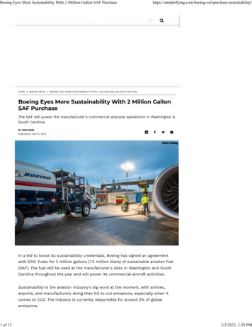
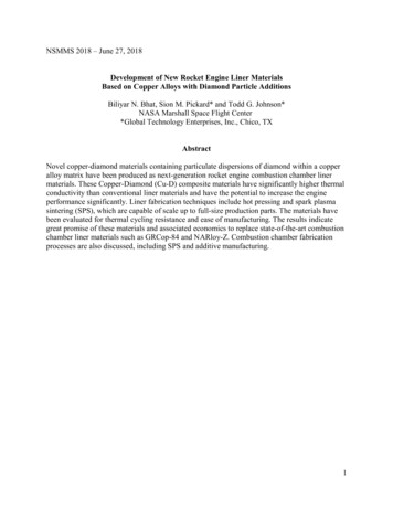
Vehicle IdentificationVehicle Certification Plate andData PlateNOTE: Labels shown in this chapter are examples only. Actual label locations and specifications may vary from vehicle to vehicle.The certification plate is installed on the inside roofliner above the driver’s window, or on the front bulkhead. The certification plate indicates compliancewith all Federal Motor Vehicle Safety Standards(FMVSS) at the time of manufacture, gross axleweight rating (GAWR) front and rear, gross vehicleweight rating (GVWR), vehicle identification number(VIN), vehicle type, body identification, and builddate. See Fig. 1.1.HIGH POINT NORTH CAROLINAMFD BY THOMAS BUILT BUSES INC.DATE:CHASSIS YARD NO.:MODEL YEAR:ENGINE:SER NO:TRANS:SER NO:FRONT AXLE:MOD NO:INT AXLE:MOD NO:REAR AXLE:MOD NO:02/17/2004f080136Fig. 1.2, Vehicle Data PlateBuses purchased in the U.S. are marked as certifiedby means of an FMVSS certification label. SeeFig. 1.3. The tire and rim information are combinedinto one label. This label is located in the driver area.HIGH POINT NORTH CAROLINAMFD BY THOMAS BUILT BUSES INC.INC VEH MFD BY:13GVWR:GAWR FRONT:GAWR REAR:THIS VEHICLE CONFORMS TO ALL APPLICABLE FEDERAL MOTOR VEHICLESAFETY STANDARDS IN EFFECT IN:VEH. TYPE:V.I.N.:BODY ID:CHASSIS ID NO:01/16/200911/14/2001f080137 chassis identification numberf0801181. Date of Manufacture2. Gross Vehicle Weight Rating3. Gross Axle Weight RatingFig. 1.3, Vehicle Certification LabelFig. 1.1, Certification PlateThe data plate is installed on the inside roof linerabove the driver’s window, or on the front bulkhead,and lists manufacturing information. See Fig. 1.2.Whenever contacting parts, service, or warranty personnel regarding the vehicle, the following threenumbers will be requested:2Chassis built without a cargo body that are intendedfor service in the U.S. have an incomplete vehiclecertification label attached by the final-stage manufacturer. See Fig. 1.4. This label will be attached tothe incomplete vehicle document included with thevehicle, and certifies that the vehicle conforms to allapplicable FMVSS regulations in effect on the date ofcompletion. body identification number VINFederal Motor Vehicle SafetyStandard LabelsNOTE: Due to the variety of Federal Motor Vehicle Safety Standard (FMVSS) certification requirements, not all of the labels shown will applyto your vehicle.1.111/14/2001f080120Fig. 1.4, Incomplete Vehicle Certification LabelThe tire and rim portion of the FMVSS certificationlabel certifies suitable tire and rim combinations thatcan be installed on the vehicle, for the given grossaxle weight rating. Tires and rims installed on thevehicle at the time of manufacture may have a higher
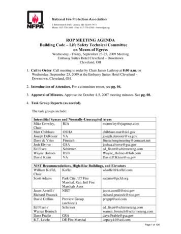
Vehicle Identificationload capacity than that certified by the tire and rimlabel. If the tires and rims currently on the vehiclehave a lower load capacity than that shown on thetire and rim label, then the tires and rims determinethe load limitations on each of the axles.Canadian Motor Vehicle SafetyStandard LabelsIn Canada, buses are marked as certified by meansof a statement of compliance label with the CanadianNational Safety Mark, which is located in the driverarea. See Fig. 1.5.2111/14/2001f0801191. Gross Weight Rating By Component in Axle System2. Gross Vehicle Weight Rating By Component inVehicle as a WholeFig. 1.6, Tire and Rim InformationVehicle LoadingThe gross axle weight rating (GAWR) is the maximum weight the axle can carry. GAWR is the combined capacity of the axle, brakes, tires, wheel equipment, and suspension.The gross vehicle weight rating (GVWR) is the maximum loaded weight of the vehicle. See Fig. 1.3.NOTICE10/10/2006f080024Fig. 1.5, Canadian National Safety MarkIf purchased for service in Canada, chassis builtwithout a body are marked as certified by a "Statement of Compliance" label. See Fig. 1.3. This labelmust be attached by the final-stage manufacturer tocertify that the vehicle conforms to all applicableCanada Motor Vehicle Safety Standard (CMVSS)regulations in effect on the date of completion.Tire and Rim InformationThe tire and rim label certifies suitable tire and rimcombinations that can be installed on the vehicle forthe given gross axle weight rating. Tires and rimsinstalled on the vehicle at the time of manufacturemay have a higher load capacity than that certifiedby the tire and rim label. If the tires and rims currently on the vehicle have a lower load capacity thanthat shown on the tire and rim label, then the tiresand rims determine the load limitations on each ofthe axles.See Fig. 1.6 for U.S. and Canadian tire and rimlabels.Never load the vehicle over the GVWR. Considerable damage to the drivetrain may result if thevehicle is over the GVWR.IMPORTANT: Passenger and cargo loadsshould be distributed proportionately over boththe front and rear axles, and sides of the bus.NOTE: Actual loads on the front and rear axlescan only be determined by weighing the vehicleat highway weigh stations or similar facilities.Overloading the vehicle is considered misuseand will void the vehicle warranty.Emissions LabelsEPA Noise Emission Control LabelA vehicle noise emission control label is attachedeither to the left side of the dashboard or in thedriver’s area. See Fig. 1.7.It is the owner’s responsibility to maintain the vehicleso that it conforms to EPA regulations.IMPORTANT: Certain incomplete vehicles maybe produced with incomplete noise control hardware. Such vehicles will not have a vehiclenoise emission control information label. For1.2
Vehicle IdentificationVEHICLE NOISE EMISSION CONTROL INFORMATIONDATE OF MANUFACTURE 01/96FREIGHTLINER CORPORATIONTHIS VEHICLE CONFORMS TO U.S. EPA REGULATIONS FOR NOISE EMISSIONAPPLICABLE TO MEDIUM AND HEAVY TRUCKS.THE FOLLOWING ACTS OR THE CAUSING THEREOF BY ANY PERSON ARE PROHIBITED BYTHE NOISE CONTROL ACT OF 1972:A. THE REMOVAL OR RENDERING INOPERATIVE, OTHER THAN FOR PURPOSES OFMAINTENANCE, REPAIR, OR REPLACEMENT, OF ANY NOISE CONTROL DEVICE ORELEMENT OF DESIGN (LISTED IN THE OWNER’S MANUAL) INCORPORATED INTO THISVEHICLE IN COMPLIANCE WITH THE NOISE CONTROL ACT.B. THE USE THIS VEHICLE AFTER SUCH DEVICE OR ELEMENT OF DESIGN HASBEEN REMOVED OR RENDERED INOPERATIVE.24 00273 02010/06/98f080026Fig. 1.7, Vehicle Noise Emission Control Labelsuch vehicles, it is the final-stage manufacturer’s responsibility to complete the vehicle inconformity to U.S. EPA regulations (40 CFR Part205) and label it for compliance.Aftertreatment System IndicatorsLabelEngines and vehicles manufactured after December31, 2006 and domiciled in the U.S. or Canada arerequired to meet all EPA regulations effective as ofthe vehicle build date, and are equipped with anemission aftertreatment system (ATS). Vehicles domiciled outside of the U.S. and Canada may nothave aftertreatment equipment, depending upon localstatutory emissions guidelines. See Table 1.1.There is a warning label (placement will vary bybodybuilder) for important warning indicators in theinstrument cluster that pertain to the ATS.It is a violation of U.S. federal law to alter exhaustplumbing, ATS, or other components in any way thatwould bring the engine/vehicle out of compliance withcertification requirements [Ref: 42 U.S.C. S7522(a)(3)]. It is the owner’s responsibility to maintain thevehicle so that it conforms to EPA regulations.Vehicle Emission Control InformationLabelModel year 2013 and later vehicles meet additionalrequirements as specified by federal greenhouse gasand fuel efficiency regulations (GHG14). These vehicles may be equipped with components, such aslow-rolling resistance tires, that increase fuel efficiency and reduce GHG emissions.A Vehicle Emission Control Information label is located on the fan shroud. See Fig. 1.8. It is the owner’s responsibility to maintain the vehicle so that itconforms to EPA and NHTSA regulations.1.303/02/2012f080183Fig. 1.8, Vehicle Emission Control Information Label
Vehicle IdentificationApplicable Emissions System Based on Build Date and EPA RegulationsBuild DateRegulation: Emissions ComponentsEPA07 (reduce nitrogen oxides (NOx) emissions to 1.1 g/bhp-hr, and reduceJanuary 1, 2007–December 31,particulate matter emissions to 0.01 g/bhp-hr): Aftertreatment device (ATD) containing2009a diesel particulate filter that traps soot and ash.*EPA10 (reduce NOx emissions to 0.2 g/bhp-hr): EPA07-type ATD, with additionalJanuary 1, 2010–December 31,selective catalyst reduction (SCR) technology that utilizes diesel exhaust fluid (DEF)2012to convert NOx to nitrogen and water vapor.GHG14: Aerodynamic and fuel efficiency components including low-rolling resistanceFrom March 5, 2012tires specifically designed to meet regulatory fuel efficiency and greenhouse gasemissions standards.* Cummins, Detroit, and Mercedes-Benz ATD’s are also equipped with a diesel oxidation catalyst to break down pollutants.Table 1.1, Applicable Emissions System Based on Build Date and EPA Regulations1.4
2Vehicle AccessAssist Rails and Access Steps . . . . . . . . . . . . . . . . . . . . . . . . . . . . . . . . . . . . . . . . . . . . . . . . . . . . . .Entering and Exiting the Bus . . . . . . . . . . . . . . . . . . . . . . . . . . . . . . . . . . . . . . . . . . . . . . . . . . . . . . . .Front Door Opening and Closing . . . . . . . . . . . . . . . . . . . . . . . . . . . . . . . . . . . . . . . . . . . . . . . . . . . . .Battery Access . . . . . . . . . . . . . . . . . . . . . . . . . . . . . . . . . . . . . . . . . . . . . . . . . . . . . . . . . . . . . . . . . . .Hood Opening and Closing . . . . . . . . . . . . . . . . . . . . . . . . . . . . . . . . . . . . . . . . . . . . . . . . . . . . . . . . .Emergency Roof Escape Hatch . . . . . . . . . . . . . . . . . . . . . . . . . . . . . . . . . . . . . . . . . . . . . . . . . . . . . .Emergency Door . . . . . . . . . . . . . . . . . . . . . . . . . . . . . . . . . . . . . . . . . . . . . . . . . . . . . . . . . . . . . . . . . .Emergency Window Exits . . . . . . . . . . . . . . . . . . . . . . . . . . . . . . . . . . . . . . . . . . . . . . . . . . . . . . . . . .2.12.12.22.22.32.42.42.5
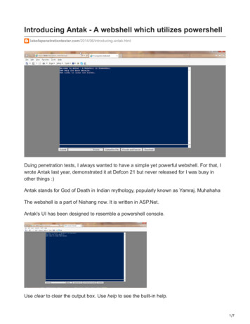
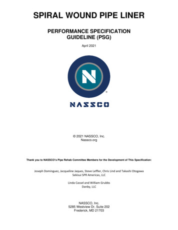
Vehicle AccessAssist Rails and Access StepsWARNINGWet or dirty shoe soles greatly increase thechance of slipping or falling. If shoe soles arewet or dirty, be especially careful when enteringor exiting the bus. Always maintain three-pointcontact with the bus access system while entering and exiting the bus. Three-point contactmeans both feet and one hand, or both handsand one foot.The two assist rails and three or four access stepsare all part of the bus access system. Use thesewhen entering or exiting the bus to increase securityand comfort.Folding Stepsing and exiting the bus. Three-point contactmeans both feet and one hand, or both handsand one foot.Stepwell LightA stepwell light is located on the bottom right-handside of the entry steps. See Fig. 2.2.Entering the Bus1.Facing the steps, grasp the assist rail on eitherside of the steps. See Fig. 2.2. Reach up as faras is comfortable.2.Place your right foot on the bottom step, and pullyourself up.3.Place your left foot on the middle step.4.Place your right foot on the top step.Folding steps mounted on both sides of the bus assist in cleaning the windshield. The steps should bekept clean and the pivot points should be kept lubricated. See Fig. 2.1.22113111/20/2003f602148Fig. 2.1, Folding Step1. Steps2. Assist RailsEntering and Exiting the BusWARNINGWet or dirty shoe soles greatly increase thechance of slipping or falling. If shoe soles arewet or dirty, be especially careful when enteringor exiting the bus. Always maintain three-pointcontact with the bus access system while enter-2.1f60215112/05/20031. Folding Step3. Stepwell LightFig. 2.2, Bus Entry and ExitExiting the Bus1.Facing the steps, grasp the assist rail on eitherside of the steps.2.Move your right foot on the first step.3.Place your left foot on the middle step.
Vehicle Access4.Step to the ground with your right foot first.Front Door Opening andClosingBuses with Exterior Door Control2.After entering the vehicle, activate the emergency air release rocker switch located abovethe door. See Fig. 2.4.3.Start the vehicle and allow it to warm up.4.To close the door, move the paddle switch on thedriver control panel to the DOOR CLOSED position. See Fig. 2.3.Front Door OpeningOpen the front entrance door by turning the exterior key switch to the open position and enter thevehicle.Front Door Closing1.Shut down the engine.2.Start the vehicle and allow it to warm up.2.3.To close the door, move the paddle switch on thedriver control panel to the DOOR CLOSED position. See Fig. 2.3.Activate the emergency air release rocker switchlocated above the door.3.Manually push the door open and exit the vehicle.4.Close the door manually.1.Battery AccessBattery CompartmentThe battery compartment is located behind thedriver’s area, attached to the frame rail. To open thebattery access door, insert and turn the key, then pullthe access door open. Pull the pull-pin spring latchesout to slide the battery tray forward. See Fig. 2.5.With the battery access door open, it is easy to getaccess to the battery terminals for cleaning, charging, or emergency jump starting.05/29/2007f720662Fig. 2.3, Door Open/Door Closed Paddle SwitchFront Door Closing1.Shut down the engine.2.Move the paddle switch on the driver controlpanel to the DOOR OPEN position and exit thebus.3.Turn the exterior key switch to the close position.Buses without Exterior Door ControlFront Door Opening1.Manually open the door.To close the battery access door, swing the door toline up with the hole in the frame, then lock the battery access door with the key.Battery Disconnect Switch, OptionalNOTICEThe batteries must be disconnected if the vehicleis not in use for a period exceeding two weeks,or the vehicle may not start, and permanent battery damage could occur.A battery disconnect switch, if so equipped, cuts offall battery power to the vehicle. It is also used whenever the vehicle is placed out of service for extendedperiods to prevent battery discharge. The battery disconnect switch is located on the side of the batterybox. See Fig. 2.6.2.2
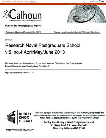
Vehicle Access321f54492501/10/20071. Emergency Switch for Main Entry Door2. Main Entry Door Emergency Release Operations Decal3. Child Reminder NoticeFig. 2.4, Emergency Switch for Main Entry DoorHood Opening and Closing4A torsion spring helps to raise and lower the hood.Hood restraint cables prevent the hood from overtravel. An optional hood damper limits the closingspeed. In the operating position, the hood is securedto the half-fenders by a hold-down latch on eachside.23Tilting the Hood2112/05/2003f5443651. Battery Access Door2. Pull-Pin Spring Latch3. Battery Tray4. BatteryFig. 2.5, Battery Access2.31.Apply the parking brakes.2.Release both hood hold-down latches by pullingthe ends outward. See Fig. 2.7.
Vehicle AccessIf needed, you can also slow the rate of descentwith your hand.3.Make sure the hood is flush with the cowl, thensecure the hood by engaging both hood holddown latches.IMPORTANT: Make sure that both hold-downlatches are fully engaged before operating thevehicle.Emergency Roof Escape Hatch01/18/95f600150aNOTE: A warning buzzer should sound whenany exit is open.The bus may have optional emergency roof escapehatches located near the front and rear of the bus.On buses equipped with an emergency roof escapehatch, the opening instructions are clearly displayedon the hatch cover. See Fig. 2.8.Fig. 2.6, Battery Disconnect Switch324110/24/2001f8805551. Fender2. Latch Hook3. Latch Handle4. Half-FenderFig. 2.7, Hood Hold-Down LatchNOTICE12/05/2003Do not let the hood free-fall to the fully open position. To do so could damage the hood or hoodstraps.3.Standing in front of the hood, tilt the rear of thehood upward until it reaches the over-center position (45-degrees from vertical). Then slowlybring it to a stop.Closing the Hood1.Push the hood over center.2.As the hood goes over center, the damper (ifequipped) automatically slows its rate of descent.f602155Fig. 2.8, Emergency Roof Escape HatchEmergency DoorRear Emergency DoorThe emergency door is located at the back of thebus. To open the door, lift the release handle andpush the door out. Once the door is completely open,it will automatically lock in the open position, allowingpassengers to exit without holding the door open. Toclose the door, push it back to release it from the2.4
Vehicle Accesslocked position. Close the door and lock it by pushing the release handle down. See Fig. 2.9.NOTE: Some states require that the operatinginstructions be located on the window glass.Using the Main Entry/Exit Door in anEmergencyVehicles Built Since January 9, 2008In an emergency, it may be necessary to use the redswitch above the main door to open the door. Pushdown on the red switch to open the door, then pushthe door open. See Fig. 2.4 and Fig. 2.10.For vehicles built since January 9, 2008, the passenger emergency window exit is a vertical push-outwindow. Lift up on the latch to open the window. Abuzzer will activate when an emergency window exitis open. See Fig. 2.11 and Fig. 2.12.Emergency Window ExitsThe bus has windows designated as emergencyexits. To open the windows in emergency situations,follow the instructions that are displayed on the window frame.NOTICETO RELEASE OPENED DOORFROM HELD POSTIION OPEN DOOR FULLY CLOSE DOOR08/26/2008f602145Fig. 2.9, Emergency Door2.5
Vehicle AccessEMERGENCY RELEASEDISENGAGE RELEASEPUSH FORWARD DOORTO RESET DOORS, DRIVER’S DOOR CONTROLS MUST BE INTHE ’OPEN’ POSITION BEFORE RE ENGAGING RELEASEEMERGENCY RELEASEDISENGAGE RELEASEPUSH FORWARD DOORTO RESET DOORS, DRIVER’S DOOR CONTROLS MUST BE INTHE ’OPEN’ POSITION BEFORE RE ENGAGING 2007f080145Fig. 2.10, Disengaging the Main Entry Door in an Emergency2.6
Vehicle Access106/20/2008f6701461. Window Latch and Buzzer Switch (closed position)Fig. 2.11, Vertical Push-Out Window (closed position)1206/20/2008f6701471. Window Latch and Buzzer Switch (open position)2. Window FrameFig. 2.12, Vertical Push-Out Window (open position)2.7
3Bus FeaturesWindows . . . . . . . . . . . . . . . . . . . . . . . . . . . . . . . . . . . . . . . . . . . . . . . . . . . . . . . . . . . . . . . . . . . . . . . .Mirrors . . . . . . . . . . . . . . . . . . . . . . . . . . . . . . . . . . . . . . . . . . . . . . . . . . . . . . . . . . . . . . . . . . . . . . . . . .Seats . . . . . . . . . . . . . . . . . . . . . . . . . . . . . . . . . . . . . . . . . . . . . . . . . . . . . . . . . . . . . . . . . . . . . . . . . . .Seat Belts and Tether Belts . . . . . . . . . . . . . . . . . . . . . . . . . . . . . . . . . . . . . . . . . . . . . . . . . . . . . . . . .Bus Amenities . . . . . . . . . . . . . . . . . . . . . . . . . . . . . . . . . . . . . . . . . . . . . . . . . . . . . . . . . . . . . . . . . . . .Windshield Washer Reservoir . . . . . . . . . . . . . . . . . . . . . . . . . . . . . . . . . . . . . . . . . . . . . . . . . . . . . . .3.13.13.23.63.83.9
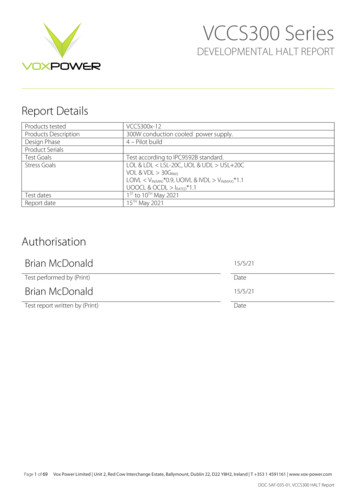
Bus FeaturesWindowsMirror Heat Switch, OptionalDriver’s WindowOne or both side-view mirrors can be heated to keepthem clear of fog, frost, and ice.To open the driver window, press the lock and slidethe window rearward. The window will only openhalf-way. See Fig. 3.1.To heat the mirrors, press the upper part of the mirror heat switch (MIRR HEAT) on the dash. SeeFig. 3.2. When the mirror heat switch is on, anamber indicator light illuminates inside the switch.1MIRRHEAT10/09/2001f610524To heat the mirrors, press up; press down to turn off theheat.Fig. 3.2, Mirror Heat SwitchThe mirror heat switch is a smart switch (fully multiplexed).Power Mirrors, OptionalThe main outside mirrors, if heated, can be equippedwith an electrical remote control located on thedriver’s switch panel. See Fig. 3.3.12/03/2003f9105141. Driver’s Window2Fig. 3.1, Driver’s WindowPassenger Windows1Passenger windows on the bus are opened by pressing the locks on the left-hand and right-hand side ofthe window. There are three settings for the passenger windows. The window can be opened to the onethird, one-half, or full-open positions.MirrorsBoth driver-side mirrors and crossover mirrors arestandard on the bus.10/05/2001f610523To adjust the mirror position, press the keypad in thedirection you want the mirror to move.1. Mirror Select Switch2. KeypadFig. 3.3, Power Mirror Switch Pad3.1
Bus FeaturesTo select the mirrors on the left-hand side, press theleft side of the mirror select switch. To select the mirrors on the right-hand side, press the right side of themirror select switch.123The keypad has four arrow keys, pointing up, down,left, and right. To adjust the mirror position, press thekeypad in the direction you want the mirror to move.SeatsGeneral Information12/02/2003WARNINGf9105121. Seat Slide2. Lumbar SupportKeep hands, tools, and other objects away fromthe scissor points under the seats. Failure to doso could cause personal injury.3. IsolatorFig. 3.4, Seat Slide and Iso
Emissions and Fuel Efficiency Compliance This vehicle must be regularly inspected and main-tained as indicated in the Saf-T-Liner C2 Mainte-nance Manual, and in the Pre- and Post-Trip Inspec-tions and Maintenance chapter in this manual, in order to continue satisfactory performance and en-sure coverage of the vehicle under the manufactur-er's .