Transcription
VCCS300 SeriesDEVELOPMENTAL HALT REPORTReport DetailsProducts testedProducts DescriptionDesign PhaseProduct SerialsTest GoalsStress GoalsTest datesReport dateVCCS300x-12300W conduction cooled power supply.4 – Pilot buildTest according to IPC9592B standard.LOL & LDL LSL-20C, UOL & UDL USL 20CVOL & VDL 30GRMSLOIVL VIN(MIN)*0.9, UOIVL & IVDL VIN(MAX)*1.1UOOCL & OCDL IRATED*1.11ST to 10TH May 202115TH May 2021AuthorisationBrian McDonald15/5/21Test performed by (Print)DateBrian McDonald15/5/21Test report written by (Print)DatePage 1 of 69Vox Power Limited Unit 2, Red Cow Interchange Estate, Ballymount, Dublin 22, D22 Y8H2, Ireland T 353 1 4591161 www.vox-power.comDOC-SAF-035-01, VCCS300 HALT Report
1. ObjectiveHighly Accelerated Life Testing (HALT) is a requirement of IPC-9592B and is performed throughout the development.cycle. HALT consists of applying environmental and electrical stresses beyond specification limits to identifyweaknesses that may point to insufficient margin in the design.In order to ruggedise the product, the root cause of each failure needs to be determined and the problems correcteduntil the fundamental limit of the technology used in the product design can be reached. This process will yield thewidest possible margin between product capabilities and the environment in which it operates, thus increasing theproduct’s reliability, reducing the number of field returns and realizing long-term savings.Limits referenced in HALT are listed below:AbbreviationDescriptionLSL/USLLower/Upper specification limits. (Defined in the product datasheet)LOL/UOLLower/Upper operational limits.(Product may fail to meet specification but recovers once returned within LSL/USL limits.LDL/UDLLower/Upper destruct limits. (Product fails and does not recover)VOL/VDLVibration Operational Limit/Vibration Destruct Limit.LOIVL/UOIVLLower/Upper Operational Input Voltage Limits.IVDLInput Voltage Destruct Limit.UOOCL/OCDL Upper Operational Output Current Limit/Output Current Destruct LimitPage 2 of 69Vox Power Limited Unit 2, Red Cow Interchange Estate, Ballymount, Dublin 22, D22 Y8H2, Ireland T 353 1 4591161 www.vox-power.comDOC-SAF-035-01, VCCS300 HALT Report
2. Executive summaryThe table below gives a quick reference to the results obtained and any relevant test notes. A more in depthdescription of the test process and results is given in section 5.Several test variants were performed to cover the worst-case stress points while adhering to specified line deratings.The test setup attempts to maintain the product temperature as close as possible to the ambient chambertemperature but there can still be significant differences. It is important to note that temperature test limit results arerecorded as the ambient temperature rather than the product temperature.2.1 Summary of product operating and destruct limitsTest NameTest arginLow TemperatureLimit(IPC9592B-D.1.1.1)VAC 85V,120V,220VLOL -60 CLDL -60 CLSL -40 C 20 CHigh TemperatureLimit(IPC9592B-D.1.1.2)VAC 85V,120V,220VUOL 105 CUDL 120 CThermal Cycle(IPC9592B-D.1.1.3)Random Vibration(IPC9592B-D.1.1.4)VAC 220VVAC 120VInput Voltage Limit(IPC9592B-D.1.1.5)VAC NOM 85V,120VOutput Load Limit(IPC9592B-D.1.1.6)POUT NOM 300WCombined Stress(IPC9592B-D.1.1.7)Notes:1.2.3.4.5.6.VAC 120V-50 C to 80 C30 cyclesVOL 40GRMSVDL 40GRMSLOIVL 85 61VACLOIVL 120 93VACUOIVL 300VACIVDL 300VACUOOCL IRATED*1.25OCDL IRATED*1.3-50 C to 95 C102.3VAC to 270VACIrated*1.1255 cycles to 36GRMSNotesTest stopped at 60 C. No Failures.USL 50 C55 CTest stopped at120 C. No Failures.OP OTP disabled.IP OTP enabled.NANANo Failures.30 GRMS10 GRMSNo Failures.VAC MIN*0.9VAC MAX*1.1VAC MIN*0.78VAC MAX*1.1385V Test stopped at42V. No Failures.120V Test stoppedat 61V. No Failures.IP OCP enabled.IRATED*1.1IRATED*0.15No Failures.NANo Failures.OP OTP disabled.IP OTP enabled.IP OCP enabled.NAAll temperature values are chamber setpoints unless stated otherwise. See appendix F for product levels.All Vibration values are product mounting plate measurements unless stated otherwise. See appendix F for chamber setpoints.The operating limit is defined as the applied stress below which the product is fully functional.The destruct limit is defined as the applied stress below which the product returns to full operation when the applied stress isdecreased to within the operating limit.When the limit is preceded by a “ ” or “ ” sign it indicates that the test was stopped prior to a failure, either because of a limitation ofthe chamber, the test setup, or per customer request.The limits shown are the worst-case limits. In other words, the limits for the product that had the lowest limits of all units tested underthat stress. These limits reflect the product limits before any modifications.2.2 ConclusionsThe testing carried out has shown that the product meets or exceeds the required margins for all parameters.Page 3 of 69Vox Power Limited Unit 2, Red Cow Interchange Estate, Ballymount, Dublin 22, D22 Y8H2, Ireland T 353 1 4591161 www.vox-power.comDOC-SAF-035-01, VCCS300 HALT Report
3. HALT process descriptionThe test procedure followed is outlined in the IPC9592B standard. Any deviations from this procedure are noted in therelevant report sections.3.1 Low Temperature Limit Test (IPC9592B-D.1.1.1)The low temperature limits test involves operating the device under test at 25 C ambient with no vibration. The deviceis turned off and the temperature is decreased in defined steps. A functional test is performed after each temperaturedecrement and dwell and the test continues until the device under test fails or the chamber minimum temperature isreached.Line deratingsThe test is performed at the minimum input voltage allowed for full power output (eg. No power derating, 120Vac) andat the minimum line voltage allowed with derating (eg. Power derated, 85VAC).Note: Different Lower Operating Limit temperatures may be identified and the relevant LOL should be used forsubsequent tests.DUT preparationAny negative temperature protection circuitry shall be disabled during this testing, where possible.3.2 High Temperature Performance & Limit Test (IPC9592B-D.1.1.2)The high temperature limits test consists of operating the device under test at 25 C ambient with no vibration. Thedevice is turned off and the temperature is increased in defined steps. A functional test is performed after eachtemperature increment and dwell and the test continues until the device under test fails or the chamber maximumtemperature is reached.Line deratingsThe test is performed at the minimum input voltage allowed for full power output (eg. Full Power, 120VAC) and at theminimum line voltage allowed with derating (eg. Power derated, 85VAC).Note: Different Lower Operating Limit temperatures may be identified and the relevant LOL should be used forsubsequent tests.OTP operationThe test is first performed (minimum rated input voltage for maximum output power) with OTP enabled to ensurecorrect operation of OTP (Performance test. See Appendix F2), then tested with OTP disabled to determine the productstress limits and failure modes (Limits test. See Appendix F3).DUT preparationAny positive temperature protection circuitry shall be disabled during the limits test, where possible.3.3 Rapid Thermal Cycle Test (IPC9592B-D.1.1.3)The rapid thermal cycle test consists of operating the device with no vibration between the Thermal LOL 10 C andThermal UOL-10 C at the maximum possible thermal transition.A functional test is required following each dwell time of this procedure.Line deratingsThe test will be performed at the minimum input voltage allowed for full power output (eg. Full Power, 120VAC) and therelevant LOL from the lower temperature limit test.DUT preparationAny negative or positive temperature protection circuitry shall be disabled during the test, where possible.Page 4 of 69Vox Power Limited Unit 2, Red Cow Interchange Estate, Ballymount, Dublin 22, D22 Y8H2, Ireland T 353 1 4591161 www.vox-power.comDOC-SAF-035-01, VCCS300 HALT Report
3.4 Random Vibration Limits Test (IPC9592B-D.1.1.4)The random vibration limit test consists of operating the device under test at 25 C ambient and no vibration. Thevibration is then increased in steps and held for a specific dwell time until the device under test fails or the chambermaximum vibration is reached.A functional test is required following each increment and dwell time of this procedure.DUT preparationProtection circuitry shall not be disabled during the test.3.5 Input Voltage Test (IPC9592B-D.1.1.5)The objective of the Input Voltage Test is to stress the input section of the DUT to determine the operating anddestruct limits of the product. The test consists of decreasing and increasing the input mains voltage in order to findthe minimum and maximum operating and destructive limits.No functional test is required during the steps of this procedure.Line deratingsThe test is performed at the minimum mains input voltage allowed for full power output (eg. Full Power, 120VAC) and atthe minimum mains input voltage allowed with derating (eg. Power derated, 85VAC).Note: Different Lower Operating Limit temperatures may have been identified in the Low temperature limit test andthe relevant LOL should be used for each tests.DUT preparationAny negative or positive temperature protection circuitry shall be disabled during the test, where possible.Any under voltage protection (UVP)circuitry shall be disabled during the test, where possible.Any over power protection (OPP) circuitry shall be disabled during the test, where possible.3.6 Output Load Test (IPC9592B-D.1.1.6)The objective of the Output Load Test is to stress the output section of the DUT to determine the operating anddestruct limits of the product. The test will continue until failure, or test equipment limitation, in order to identify thecomponent(s) or circuits that may be damaged due to excessive current. The test consists of increasing the loadcurrent in steps from the maximum specified operating current until the unit’s output drops out of regulation, the unitfails catastrophically, or test equipment limitation is reached.No functional test is required during the steps of this procedure.DUT preparationAny negative or positive temperature protection circuitry shall be disabled during the test, if possible.Any over current protection circuit shall be disabled during this test, if possible.3.7 Combined Stress Test (IPC9592B-D.1.1.7)The Combined Stress Test operates the device under test while combining the environmental effects of randomvibration and rapid thermal cycling along with Input Voltage and Output Load transients.No functional test is required during the steps of this procedure.DUT preparationAny negative or positive temperature protection circuitry shall be disabled during the test, if possible.Any over current protection circuit shall be disabled during this test, if possible.Page 5 of 69Vox Power Limited Unit 2, Red Cow Interchange Estate, Ballymount, Dublin 22, D22 Y8H2, Ireland T 353 1 4591161 www.vox-power.comDOC-SAF-035-01, VCCS300 HALT Report
4. HALT setup4.1 Description of Test EquipmentThe test equipment listed in table 2 below was used to carry out the HALT test.DescriptionThermal & Vibration test chamberThermal test ChamberAC SourceElectronic LoadElectronic LoadOscilloscopeDataloggerPower MeterVibration Meter (True RMS)Accelerometer (IEPE)Table 2 – Equipment descriptionManufacturerModelQualmarkOVS 1.5VotschVT7010Chroma61505Chroma6314A 63103Ax4Chroma6314A tran4151HLDytran3030B5S/N1512990366 (VOX0017)521/83674 (VOX0015)000685 (VOX0097)0003599 (VOX0098)0003598 (VOX0099)MY53160421 (VOX0095)MY41025109 (VOX0070)662021001062 (VOX0101)325 (VOX0110)15101 (VOX0111)4.2 Data collectionVarious environmental, electrical and product performance data is collected and logged at regular intervals throughoutthe process. Thermocouples are attached to various points on the devices under test using kapton tape or adhesive.The data to be collected is listed in the table below and the test results are detailed in appendix F.TypeTimeStepChamber Temp. ( C)Chamber Vibration (GRMS)Chamber Temp. DL ( C)Product Temp. DL ( C)Product Vibration (GRMS)Output Voltage (VDC)Output Current 1 (A)Output Current 2 (A)Output Current Total (A)Input Voltage (VRMS)Input Power (W)Power FactorOutput Power (W)EfficiencyTable 3 – Data to be collectedDescriptionTime stampStep number of test sequenceChamber air temperature (Read from Chamber)Table accelerometerChamber air temperature (Read from Datalogger - thermocouple)Product temperature – (Read from Datalogger - thermocouple)Product vibration (Read from Scope – accelerometer at product mount)Product output voltageProduct output current in load 1Product output current in load 2Calculated: Sum of output current 1 and 2Product input voltageProduct input powerProduct input power-factorProduct output powerProduct efficiency4.3 Functional TestThe device under test was connected to external equipment and was functionally tested as described in the FunctionalTest Profile (Appendix C) when called by the HALT Test Profile (Appendix D. Line 29).Page 6 of 69Vox Power Limited Unit 2, Red Cow Interchange Estate, Ballymount, Dublin 22, D22 Y8H2, Ireland T 353 1 4591161 www.vox-power.comDOC-SAF-035-01, VCCS300 HALT Report
4.4 DUT Configuration and Ratings4.4.1 DUT Ratings4.4.1.1 Input & output electrical ratingsThe product datasheet electrical ratings are shown below. Functional test limits are based on the limits given, howeverat extreme temperatures these limits may not be met. This does not necessarily constitute a failure and each resultmust be judged individually.4.4.1.2 Mains voltage deratingsThe product has a mains voltage derating as shown below. To cover typical working ranges in the testing some testswill be performed at 85VAC or 120VAC or 220VAC or some combination of these.Page 7 of 69Vox Power Limited Unit 2, Red Cow Interchange Estate, Ballymount, Dublin 22, D22 Y8H2, Ireland T 353 1 4591161 www.vox-power.comDOC-SAF-035-01, VCCS300 HALT Report
Where an output power derating applies, it shall be implemented. For example, the Input voltage test may be carriedout at a nominal mains voltage of 85VAC. In this case the nominal output power will be set at 212.5W. The output powerwill not be adjusted further as the input voltage changes throughout the test.4.4.1.3 Thermal ratingsThe VCCS300 PSU is a conduction cooled product that has operational thermal limits on both the ambientenvironment and the product baseplate as detailed below.In order to carry out the HALT test efficiently, the product will be evaluated for forced air and conduction cooled ratingsonly. Thermal tests will be setup to minimise the temperature differential between chamber ambient and product.4.4.2 DUT ConfigurationThe device under test (DUT) is a VCCS300M-12 which has the configuration shown below.MODEL12VVo12Io25Po300Line Low85Line Mid120Line High264PWR Low212.5PWR Mid300The 12V series model is considered worst-case representative model. No other series members were tested.Page 8 of 69Vox Power Limited Unit 2, Red Cow Interchange Estate, Ballymount, Dublin 22, D22 Y8H2, Ireland T 353 1 4591161 www.vox-power.comDOC-SAF-035-01, VCCS300 HALT Report
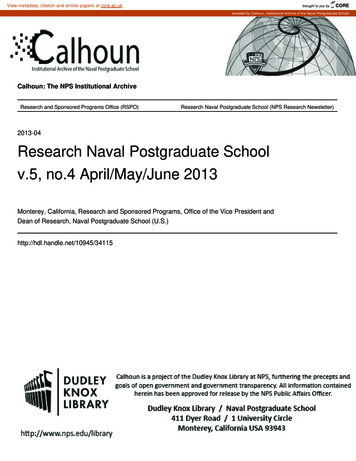
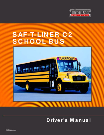
4.4.3 DUT ProtectionsThe DUT has several protection mechanisms to prevent failure of the device under abnormal operating conditions. Forcertain HALT tests it is required to disable these protections. Details of how the protections were disabled are givenbelow.Over Temperature Protection (OTP)The output circuitry has one OTP implemented with switching type PTC thermistor in positions 60A.RT1. [OP OTP]The primary power circuitry has one OTP implemented with switching type PTC thermistors in position 60D.RT1.[IP OTP]OP OTP was disabled for the following tests by shorting the 60A.RT1 PTC device. High Temperature Limit Test Rapid Thermal Cycle Test Random Vibration Limit Test Input Voltage Test Output Load Test Combined Stress TestIP OTP was not disabled for any tests.Over Current Protection (OCP)All outputs have over current protection set at approximately 115% of the rated current.OP OCP was disabled for the following tests by shorting 60A.U4.2 to 60A.U4.3. Output Load Test Combined Stress TestThe input module has an overcurrent protection on the PFC stage.It is not possible to disable the IP OCP.Over Power Protection (OPP)The product does not have a specific over power protection.Under Voltage Protection (UVP)The product does not have a specific under voltage protection.4.5 Fixturing and AirflowThe products are tested one unit at a time. For vibration testing each product under test was secured to the vibrationtable using a custom mounting fixture. The vibration mounting fixture was designed to maximize transmission ofkinetic energy from the vibration table to the product. The vibration measurement is made on the mounting fixtureclose to the product and a closed loop system is used to maintain the correct vibration level at that measurementpoint. For thermal tests the product temperature should be maintained as closely as possible to the ambienttemperature. To achieve this, the unit is mounted on a heatsink which has a fan attached and the chamber airflow isdirected onto the product. Pictures illustrating the fixturing and arrangement of test units in the test chamber arepresented in appendix A.Page 9 of 69Vox Power Limited Unit 2, Red Cow Interchange Estate, Ballymount, Dublin 22, D22 Y8H2, Ireland T 353 1 4591161 www.vox-power.comDOC-SAF-035-01, VCCS300 HALT Report
5. Detailed HALT resultsWhen interpreting the test results it is important to note that the thermal operational and destruct limit results arebased on the temperature of the given process step where the product ceased operating or was destroyed. The actualproduct ambient temperature and product temperature may differ from the process step temperature.5.1 Low Temperature Limits Test (IPC9592B-D.1.1.1)Three tests were performed as detailed below.Test #123POUT (W)300300212.5VIN NOM (VRMS)22012085TMIN ( C)-60-60-60TMAX ( C)252525The DUT was subjected to cold thermal stress beginning at 25 C, with the temperature decreasing (as per the stressprofile in appendix B) as far as -60 C.For the VAC 85V test, the output load was reduced to 212.5W in accordance with the line deratings specified in theproduct datasheet.For all tests the DUT operated correctly and passed all functional tests down to a chamber temperature of -60 C.Testing stopped at a chamber temperature of -60 C. The DUT remained operational when returned to 25 C and no LDLwas observed.The Lower Operating Limit of the product was -60 C.The Lower Destruct Limit of the product was less than -60 C.5.2 High Temperature Limits Test (IPC9592B-D.1.1.2)Three tests were performed as detailed below.Test #123POUT (W)300300212.5VIN NOM (VRMS)22012085TMIN ( C)252525TMAX ( C)120120120The DUT was subjected to hot thermal stress beginning at 25 C, with the temperature increasing (as per the stressprofile in appendix B) as far as 120 C.For the VAC 85V test, the output load was reduced to 212.5W in accordance with the line deratings specified in theproduct datasheet.For all tests the DUT operated correctly and passed all functional tests up to a chamber temperature of 105 C.Testing stopped at a chamber temperature of 120 C. The DUT remained operational when returned to 25 C and noUDL was observed.The Upper Operating Limit of the product was 105 C.The Upper Destruct Limit of the product was greater than 120 C.5.3 Rapid Thermal Cycle Test (IPC9592B-D.1.1.3)The rapid thermal cycle test was performed at 300W with a minimum nominal operating voltage of 220Vac.The DUT was subjected to cold and hot thermal stresses as per the stress profile in appendix B.The DUT operated correctly and passed all functional tests over 30 cycles. The unit was disassembled and inspectedafter the test. No issues were observed.5.4 Random Vibration Limits Test (IPC9592B-D.1.1.4)The random vibration test was performed at 300W with a minimum nominal operating voltage of 120Vac and at anambient temperature of 25 C.Page 10 of 69Vox Power Limited Unit 2, Red Cow Interchange Estate, Ballymount, Dublin 22, D22 Y8H2, Ireland T 353 1 4591161 www.vox-power.comDOC-SAF-035-01, VCCS300 HALT Report
The DUT was subjected to vibration stresses as per the stress profile in appendix B.The DUT operated correctly and passed all functional tests up to a vibration level of 40GRMS at which point the test wasterminated. The unit was disassembled and inspected after the test. No issues were observed.The Vibration Operating Limit of the product was 40GRMS.The Vibration Destruct Limit of the product was 40GRMS.5.5 Input Voltage Limit Test (IPC9592B-D.1.1.5)Two tests were performed as detailed below.Test#12POUT(W)300212.5VMIN NOM(VRMS)12085VMAX NOM(VRMS)264264TMIN( C)-55-55TMAX( C)9595VTEST MIN(VRMS)6142VTEST MAX(VRMS)300300The DUT was subjected to input voltage stresses as per the stress profiles in appendix B.For the VAC 85V test, the output load was reduced to 212.5W in accordance with the line deratings specified in theproduct datasheet.Test # 1 resultsThe DUT operated correctly down to 93VAC. From 92VAC to 61VAC, the unit entered hiccup mode due to input OCP. Nofailures occurred.The DUT operated correctly up to 300VAC at which point the test was stopped. No failures occurred.Above 270VAC the power factor was reduced due to peak input voltage greater than internal 380V bus voltage.Test # 2 resultsThe DUT operated correctly down to 61VAC. From 60VAC to 42VAC, the unit entered hiccup mode due to input OCP. Nofailures occurred.The DUT operated correctly up to 300VAC at which point the test was stopped. No failures occurred.Above 270VAC the power factor was reduced due to peak input voltage greater than internal 380V bus voltage.The Lower Operating Input Voltage Limit of the product was 93VAC @120VACNOM & 61VAC @85VACNOMThe Upper Operating Input Voltage Limit of the product was 300VAC.The Input Voltage Destruct Limit of the product was 300VAC.5.6 Output Load Limit Test (IPC9592B-D.1.1.6)The output load limit test was performed at 300W using the results from the input voltage limit test #1. The final testparameters are detailed below.POUT NOM (W)300TMIN ( C)-55TMAX ( C)95VTEST MIN (VRMS)98 (93V*1.05)VTEST MAX (VRMS)285 (300V*0.95)The DUT was subjected to output load stresses as per the stress profile in appendix B.The unit operated correctly up to 125% of the rated load (31.25A).At 130% of the rated load (32.5A) and low input voltage the output voltage dropped to approximately 93% of nominal.At 130% of the rated load (32.5A) and high input voltage the output voltage remained within specification.This could be an indication of IP OCP limiting the input power rather than a limitation of the output stage.The test was stopped at 130% of rated load. No failures occurred.The Upper Operating Limit of the product was 125% of IRATED.The Upper Destruct Limit of the product was greater than 130% of IRATED.Page 11 of 69Vox Power Limited Unit 2, Red Cow Interchange Estate, Ballymount, Dublin 22, D22 Y8H2, Ireland T 353 1 4591161 www.vox-power.comDOC-SAF-035-01, VCCS300 HALT Report
5.7 Combined Stress Test (IPC9592B-D.1.1.7)The DUT was subjected to combined stresses as per the stress profile in appendix B. Summary parameters are shownbelow.TMIN ( C)-50TMAX ( C)95GVIB MAX (GRMS)36VIN MIN (VRMS)102.3VIN MAX (VRMS)270IOUT MAX(%IRATED)112.5The DUT operated correctly and passed all functional tests over 5 cycles. The unit was disassembled and inspected afterthe tests. No issues were observed.Page 12 of 69Vox Power Limited Unit 2, Red Cow Interchange Estate, Ballymount, Dublin 22, D22 Y8H2, Ireland T 353 1 4591161 www.vox-power.comDOC-SAF-035-01, VCCS300 HALT Report
6. HALT FailuresEach failure found during the HALT process needs to be examined and the root cause of the failure determined. Oncethe root cause of each failure is determined, engineering judgment is used to determine whether corrective actionshould be taken to fix the problem. The product should then undergo a verification HALT to ensure that the designmargins have been increased to the fundamental limit of the technology and that the fixes made did not induce newfailure modes. The ruggedisation of the product will not be increased unless each of the failures found during the HALTprocess are investigated to root cause and corrective action implemented.6.1 Failure analysisNo failures were observed.Page 13 of 69Vox Power Limited Unit 2, Red Cow Interchange Estate, Ballymount, Dublin 22, D22 Y8H2, Ireland T 353 1 4591161 www.vox-power.comDOC-SAF-035-01, VCCS300 HALT Report
Appendix A – Setup PhotographsA.1 Temperature Limit, Temperature Cycle, Input Voltage & Output Load test SetupPRODUCT TEMPPage 14 of 69Vox Power Limited Unit 2, Red Cow Interchange Estate, Ballymount, Dublin 22, D22 Y8H2, Ireland T 353 1 4591161 www.vox-power.comDOC-SAF-035-01, VCCS300 HALT Report
A.2 Vibration Limit & Combined Stress test SetupPage 15 of 69Vox Power Limited Unit 2, Red Cow Interchange Estate, Ballymount, Dublin 22, D22 Y8H2, Ireland T 353 1 4591161 www.vox-power.comDOC-SAF-035-01, VCCS300 HALT Report
Appendix B – Stress ProfilesB.1 Low Temperature Limit TestB.1.1220VAC Stress 22324252627282930313233Page 16 of 00240600600600FCN FONOFFONOFFONOFFONOFFONOFFONOFFONOFFONVox Power Limited Unit 2, Red Cow Interchange Estate, Ballymount, Dublin 22, D22 Y8H2, Ireland T 353 1 4591161 www.vox-power.comDOC-SAF-035-01, VCCS300 HALT Report
B.1.2120VAC Stress 22324252627282930313233Page 17 of 00240600600600FCN FONOFFONOFFONOFFONOFFONOFFONOFFONOFFONVox Power Limited Unit 2, Red Cow Interchange Estate, Ballymount, Dublin 22, D22 Y8H2, Ireland T 353 1 4591161 www.vox-power.comDOC-SAF-035-01, VCCS300 HALT Report
B.1.385VAC Stress 22324252627282930313233Page 18 of 40600240600240600240600240600240600240600600600FCN FONOFFONOFFONOFFONOFFONOFFONOFFONOFFONVox Power Limited Unit 2, Red Cow Interchange Estate, Ballymount, Dublin 22, D22 Y8H2, Ireland T 353 1 4591161 www.vox-power.comDOC-SAF-035-01, VCCS300 HALT Report
B.2 High Temperature Limit TestB.2.1220VAC Stress 22324252627282930313233343536373839404142Page 19 of N FONOFFONOFFVox Power Limited Unit 2, Red Cow Interchange Estate, Ballymount, Dublin 22, D22 Y8H2, Ireland T 353 1 4591161 www.vox-power.comDOC-SAF-035-01, VCCS300 HALT Report
B.2.2120VAC Stress 22324252627282930313233343536373839404142Page 20 of N FONOFFONOFFVox Power Limited Unit 2, Red Cow Interchange Estate, Ballymount, Dublin 22, D22 Y8H2, Ireland T 353 1 4591161 www.vox-p
DOC-SAF-035-01, VCCS300 HALT Report 1. Objective Highly Accelerated Life Testing (HALT) is a requirement of IPC-9592B and is performed throughout the development. cycle. HALT consists of applying environmental and electrical stresses beyond specification limits to identify weaknesses that may point to insufficient margin in the design.