Transcription
NSMMS 2018 – June 27, 2018Development of New Rocket Engine Liner MaterialsBased on Copper Alloys with Diamond Particle AdditionsBiliyar N. Bhat, Sion M. Pickard* and Todd G. Johnson*NASA Marshall Space Flight Center*Global Technology Enterprises, Inc., Chico, TXAbstractNovel copper-diamond materials containing particulate dispersions of diamond within a copperalloy matrix have been produced as next-generation rocket engine combustion chamber linermaterials. These Copper-Diamond (Cu-D) composite materials have significantly higher thermalconductivity than conventional liner materials and have the potential to increase the engineperformance significantly. Liner fabrication techniques include hot pressing and spark plasmasintering (SPS), which are capable of scale up to full-size production parts. The materials havebeen evaluated for thermal cycling resistance and ease of manufacturing. The results indicategreat promise of these materials and associated economics to replace state-of-the-art combustionchamber liner materials such as GRCop-84 and NARloy-Z. Combustion chamber fabricationprocesses are also discussed, including SPS and additive manufacturing.1
1.0 IntroductionLiquid-fueled rocket engine combustion chamber liners are regeneratively cooled to maintain ahigh heat flux so that the liner surface temperatures are well below the melting point of the liner.NARloy-Z (Cu-3 wt.% Ag-0.5 wt.% Zr alloy) is the state-of-the-art material used to make theliner in engines such as RS-25 and RS-68. The current trend is to develop copper alloys withhigher alloy content (e.g., GRCop-84, which contains 8 at.% Cr and 4 at. % Nb) to improve hightemperature capability. However, higher alloying results in a lower thermal conductivity (25%lower than Cu for GRCop-84). To alleviate this problem, it was proposed to use diamondparticles in a NARloy-Z matrix. The reported thermal conductivities of diamond vary, but canbe 3 to 6 times that of copper (Ref. 1). Addition of 40 vol.% of diamonds ( 16 wt.%) couldnearly double the thermal conductivity of NARloy-Z based upon a rule of mixtures calculation –a huge benefit. An additional benefit is lower density. NARloy-Z-40%D composite is 25%lighter than NARloy-Z. In the early days of research in this area primary goal was to increase thethermal conductivity of copper by blending diamonds with copper powder and sintering theblended powder at elevated temperatures to produce a fully dense composite. It was targeted tononstructural applications such as thermal management in electronics applications (Ref. 1). Forstructural applications in propulsion systems, however, materials with good mechanicalproperties are needed; thermal conductivity alone is not sufficient. The applications includecomponents in advanced earth-to-orbit propulsion, in-space propulsion, and nuclear thermalpropulsion systems. Component examples include combustion chamber liners, injectors and heatexchangers (Ref. 2). Combustion chamber liner is probably the most challenging application andit is the focus of this paper. Benefits of higher thermal conductivity depend on the engine designand appear to be highly significant for the expander cycle engine such as the Next GenerationEngine (RL10 –NGE). The first attempt to develop such multifunctional composite material wasreported in Ref. 2.This paper gives an overview of the development of advanced rocket engine liner materialsbased on copper alloys with diamond particle additions. In the next section (section 2) thermalconductivity of copper-diamond (Cu-D) composite is explained. Contact thermal resistancebetween diamond particles and copper matrix is discussed in some detail. The effects of diamondparticle size and the role of carbides at Cu-D interface are described. Processing techniques arediscussed next in section 3. Topics discussed are: mixing techniques for copper powder anddiamond particles, consolidation techniques such as hot pressing and Spark Plasma Sintering(SPS) and machining. Section 4 presents and discusses thermal and mechanical properties of CuD composites. Section 5 focuses on fabrication techniques to make liquid rocket enginecomponents using Cu-D material and associated challenges and approaches used. The paperconcludes with a discussion of advancing the technology readiness level of Cu-D composites forchamber liner applications.2
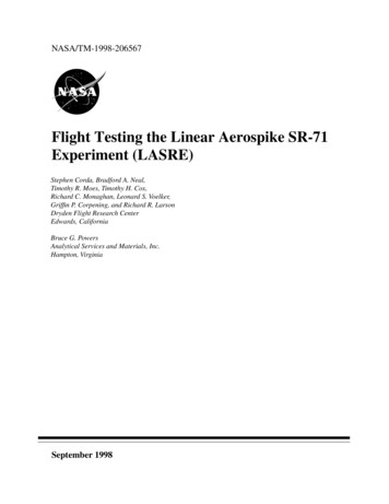
2. Thermal Conductivity of Cu-D CompositesFor liquid rocket engine combustion chamber liner applications, copper-based alloys are in usetoday because they are the most effective low-cost solution for handling extreme heat fluxes inthroat locations in regeneratively cooled designs. ‘Pure’ copper has higher thermal conductivitythan copper alloys with a value that can exceed 400W/m.K; however, it is of low strength andlacks high-temperature creep resistance. Alloying copper with other elements has beendeveloped for increased high-temperature strength and creep resistance up to servicetemperatures of 450-550⁰C at the expense of some modest loss in thermal conductivity. Forinstance, the preferred alloys for NASA liquid engine applications are NARloy-Z and GRCop84, which have estimated thermal conductivities of 320 W/m.K and 300 W/m.K respectively,compared to 360 W/m.K for ‘pure’ copper (consolidated by PM route). The ability of diamond toenhance effective thermal conductivity in Cu-based alloy designs enables lighter weight, higherthermal conductivity and intrinsically strong, creep-resistant liner materials to be developed.Early work on Cu-D composites done at Penn State (Ref.1) is shown if Fig. 1. It is interesting tonote that a simple mixture of copper and diamond powders consolidated by FAST (FieldAssisted Sintering Technology) did not show any improvement in thermal conductivity.However, significant improvement is observed when there is a carbide forming element such asZr or Cr in the copper matrix.Fig. 1: Thermal conductivity of Cu-D composites (Ref. 1)Modeling Thermal conductivity of Cu-D compositesPredictions of diamond-filled copper thermal conductivity have been attempted using solutionsfor the thermal transport problem. A commonly used relation known as the differential effectivemedium theory, or differential effective medium (DEM) scheme, comes from Bruggeman (Ref.3) and modified by Hasselman et al (Ref. 4) to allow for interface resistance effects due to finite3
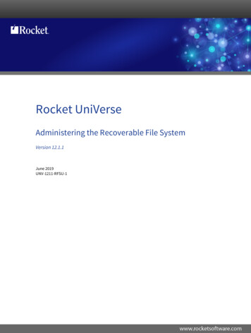
size diamond particles. This relation is often used to estimate thermal conductivity forcomposites containing high volume fractions of thermally conducting particles above 30-35%loading as given below: K(1 Vf ) m K eff3 (1 2 ) /(1 ) K eff K p (1 ) K m K p (1 ) 3/(1- )(1)where Vf is the volume fraction of particles, Km, Kp, and Keff are the thermal conductivities ofthe matrix, particle, and composite respectively, and is a dimensionless parameter dependingon interface thermal resistance (ITR) between filler particles and matrix. It is defined as ak/a,where a is the particle radius, and ak is the Kapitza radius (ak Rint.Km, where Rint ITR). For the above equation requires perfect heat transfer across the particle-matrix interface. Thethermal conductivity predicted vs. actually seen in a study of Cu-D composites by S. Pickard ofGlobal Technology Enterprises (GTE) with well-dispersed diamond particle distributions (Ref.5) is shown in Fig. 2. The values of thermal conductivity measured in this study for Vf 0.45diamonds of 137 micron mean particle size (shown by red dot) exceeded 540 W/m.K, or 1.5times the value for commercially pure Cu. The density of this Cu-D composite is 6.1 g/c.c.,which is 30% lower than for Cu alloys. We see that the best fit for the experimental data is fora value of the theoretical interfacial resistance parameter, corresponding to 0.2 in theequation above. This low value of indicates that low interfacial resistance and high thermalconductivity has been developed through processing. For calculation purposes, thermalconductivity of ‘pure’ Cu is taken as 360 W/m.K, and thermal conductivity of diamond fillerparticles is assumed to be 1800 W/m.K, which is typical of mid-quality diamond.(a)(b)Fig. 2: (a) Plot of theoretical diamond-copper thermal conductivity (Kc) normalized by matrixconductivity (Km) for various values. Experimental data points are shown that fit to predictions at some values; (b) Diamond particle distribution in wet-blended copper-diamond sample containing 40 vol. %of refractory carbide-coated diamond particles. Diamond particle size 275 microns (50/60 mesh). Thesample was made using Acumet 500A copper powder of 17 micron particle size using hot pressing (Ref.5)4
S. Pickard has also examined phonon scattering at Cu-D interface (Ref. 6). He observed thatpresence of finite ITR between the diamond particles and the ‘pure’ Cu matrix arises frommultiple sources including phonon scattering from the interface between dissimilar components(dissimilar in acoustic or elastic properties), heat carrier mismatch and weak bonding. Treatingphonons according to wave theory, and assuming transverse acoustic waves at normal incidence,the (intensity) reflection coefficient at a boundary between two different elastic materials isgiven as: Z Z 22 R 1 Z1 Z2 (2)where Z is the acoustic impedance, equal to the square root of the product of mass density andelastic modulus. Clearly, minimum reflection, and therefore maximum transmission, occurswhen Z1 Z2. Reflection, and therefore phonon scattering, increases as Z increases. If weconsider both matrix phase (Cu) and dispersed phase (diamond) of the composite to be semiinfinite, we should be able to obtain maximum transmission and therefore highest thermalconductivity by incorporating an intermediate impedance coating (analogous to an impedancematching transformer in acoustics). In the case of thermal conductivity, the optimum acousticimpedance for a coating material would be:Zcoat Z1Z2(3)Table 1 gives the acoustic impedance of several interface materials. Note that the acousticimpedance of refractory carbide ZrC is close to the optimum matching transformer impedance( 423x105 kg/ms) for a Cu-diamond interface, indicating potentially good thermal performanceof adherent refractory carbide-coated diamond in Cu matrix alloys. In experiments with the Aldiamond system, thermal conductivity is poor without a nanometer thick SiC layer on thediamond, the use of SiC coating layer is also supported by the acoustic model which shows SiCacoustic properties are intermediate to that of Al and Diamond providing good matching at theinterface.Table 1. Acoustic impedance of selected ceramics and metalsAlCuDiamond SiCZrC HfCSiGraphite B4C2003603000752022140 15030k(W/mK)Z (105136420561310424606199 44395kg/ms)241835.35.8565.6CTE(ppm/K).Coatings can be applied by a number of techniques, including chemical vapor deposition (CVD)and natural in situ carbide formation by diffusion. NARloy-Z-D composite is an example of thelatter. Coating thickness needs to be optimized based on both wave theory and experiment.5
Quantum Chemistry based Modeling of Kapitza Thermal ConductanceSmelyanzkii and Fogel have developed an analytical model of interface thermal resistance usingquantum chemistry approach (Ref. 7). They used the term Kapitza thermal conductance insteadof ITR. Their model also takes into account phonon interactions at the matrix-particle interface.Their approach focused on the Diamond-Copper matrix interface in NARloy-Z composite, whichcontains 0.5wt. % Zr. Zr is a known carbide former. The Zr in NARloy-Z matrix migrates andreacts with outermost atomic layers of diamond to form ZrC. Their findings are summarized inTable 2. The D/ZrC/Cu interface is shown to have a contact thermal conductance that is 3.5times that of the direct D/Cu interface. These findings are of interest in alloy selection andprocessing approach to developing high thermal conductivity Cu-D composites. They alsounderscore the importance of controlling diamond-carbide-metal interfaces. Refractory metalcarbides appear to be a good choice for improving the thermal conductivity. They also appear togovern the mechanical properties of the Cu-D composites. Cu-D interface voids and defects willadversely affect mechanical properties.Table 2: Contact thermal conductance for various interfacesParameterInterfaceNotes: Here θm – temperature at maximum phonon frequency (kT h x frequency where k isBoltzmann’s constant and h is Planck’s constant) – Debye’s temperature is used for θm as anapproximation. (Ref. 7)3. Processing of Copper-Diamond CompositesThis section discusses processing techniques used for making Cu-D parts, including material andprocess selection. Alloy powder and diamond particle size and distribution are important factors.Diamond particles may require coatings depending on the end application. Processing techniquesinclude mixing, sintering and consolidation by hot pressing and spark plasma sintering.Fabrication techniques are introduced in this section, but discussed in greater detail in section 5.Powder Selection – Copper & Diamond6
Copper powders are readily available commercially either as pure copper, or as alloy powders.Alloy powders include NARloy-Z, Cu-Zr, GRCop-84 and more. Powder selection is based oncost, availability and performance requirements of the end product.Diamond powders come in different particle sizes, from a few microns to a few hundredmicrons. As mentioned before larger diamonds have smaller surface to volume ratio and hencetend to give higher thermal conductivity. However, larger diamonds in the matrix make it moredifficult to machine using conventional techniques. They also tend to increase surface roughness.Quality of commercially available diamonds varies and have variable thermal conductivity,typically in the range 1500 – 2000 W/mK.Coating selection for DiamondDiamonds can be used either coated or uncoated. If the alloy matrix has a carbide former in it(e.g., Zr, Cr) coating may not be necessary. If there is no carbide former in the matrix coatingdiamonds with a refractory carbide layer such as MoC, HfC or ZrC will be necessary. Coatingprocess can be chemical vapor deposition (CVD), electrolytic or a combination there of. Carbidecoatings generally use CVD process. Metallic coatings (e.g., Cu, Ni) use electrolytic process.Coating adhesion, thickness and coverage must be controlled for best results.In addition to improving contact thermal conductance carbides improve the mechanical bondbetween diamond and copper alloy matrix, which is an important consideration in structuralcomposites. Microstructural evidence suggests that free energy of formation (ΔG) of carbides isthe main driver for atomic migration to diamond particle interface (Ref. 1). For example,zirconium carbide (ZrC) has a ΔG -173KJ/mol compared to ΔG of -76 KJ/mol for chromiumcarbide (Cr23C6). In CuCrZr-D composite ZrC is found to dominate the interface. Furthermore,ZrC at the Cu-D interface appears to form a coherent boundary with copper matrix and helps toimprove ductility. Naturally formed carbides tend to have better interfaces than coated carbidesalthough heat treatment can in principle produce a good coherent interface. It should be possibleto coat diamond with metallic Zr and form ZrC coating during sintering at elevated temperatures.Mixing techniquesPowder metallurgy techniques are commonly used to process Cu-D composites. The basicprocess is simple: copper alloy powder is mixed with diamond particles and sintered in a dieunder pressure at high temperatures to form a fully dense part. Mixing is done in a blender suchas turbula or acoustic mixer. Ball milling can also be used but diamonds can be abrasive.Diamond particles are much lighter than copper powder particles and tend to segregate easilyduring handling. Dry mixtures made this way tend produce parts with segregated microstructureas shown in Fig. 3. A binder such as isopropyl alcohol is often used during mixing (wet process)to help copper particles to adhere to diamond particles. Wet processing helps to reducesegregation and produce a more uniform microstructure (Fig. 3).7
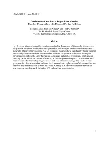
Fig. 3: Appearance of near net shape 2.75” OD x 0.125” wall x 1” tall copper-diamond rings containingVf 0.4 diamond made by dry powder blending and by a wet process using a paste-like substancecomprising the blended powder and isopropyl alchohol. The two types of powder blending were loadedinto the dies and consolidated by hot pressing at GTE. The opening of the calipers in the image are 1”.(Ref. 5)Blend by acoustic mixeror ball millHydraulicsystemCopper Powder Diamond powderPowerSupply SystemLoad powdermixture in a graphitedieVacuumchamberSinter by FASTVacuumAr / N2 / H2Fig. 4: Sequence of powder mixing and sintering by Field Assisted Sintering Technique (FAST)Consolidation techniquesDifferent techniques are available for consolidating Cu-D composites: hot pressing (HP), hotisostatic pressing (HIP), microwave sintering, and spark plasma sintering (SPS, aka field assistedsintering technology (FAST)). SPS and HP appear to be the most commonly used techniques and8
are descibed below. All techniques aim to make full density parts. Full density (near 100%dense) is required for best properties.Spark Plasma Sintering (SPS) or Field Assisted Sintering technology (FAST):This process is shown schematically in Figure 4. Blended powder is poured into a graphite (orsome other high temperature material) die and placed in the vacuum chamber of the FAST unit.After pumping down the powder is compresssed to high pressure (of the order of 10,000 psi).Powder is heated in two ways: 1) by heating the die in the furnace and 2) passing a pulsatingcurrent through the part being consolidated. Because of dual heating the heating rates are highand sintering occurs in a relatively short time, usually les than an hour. After sintering iscomplete the furnace is cooled and the die is taken out and the part removed.Hot Pressing: Blended powder is poured into a graphite (or any aother suitable material) die andplaced in a furnace chamber which is evacuated. Pressure is applied and held while the furnacetemperature is raised to sintering temperature. Unlike SPS there is no direct current passedthrough the part. Heat transfer is relatively slow in this method and sintering times are muchlonger, of the order of hours. After sintering the furnace is cooled and the part is removed fromthe die. Table 3 below shows a comparison between SPS and HP techniques.Table 3: Comparison of SPS and HP Consolidation for NARloy-Z-D compositeSPS consolidation conditionsHP consolidation20 mins at 950C, 8 Ksi Pressure, fast heating 1 hr hold at 980C, slow heating, 3C/minute (in( 500C/min) and furnace cooling700-980C range),3 hr cool down to 300C, 6Ksi pressureMachiningDiamond is the hardest material known and presents challenges for machining. Even diamondcoated tools tend to wear quickly. Electrical discharge machining works well and has been usedsuccessfully to machine test specimens. Waterjet cutting is another method that works and hasbeen used to make channels in NARloy-Z-D composite. From a machining perspective net shapemanufacturing techniques discussed below are attractive and should be pursued where possible.Additive ManufacturingAdditive manufacturing is a general term that defines a layer-by-layer fabrication method toform three-dimensional shapes as opposed to machining and joining multiple parts. Several typesof additive manufacturing have evolved over the last decade and are being advanced forcombustion devices component fabrication. This process has been used successfully to makecombustion chambers out of GRCop-84 at Marshall Space Flight Center and looks promising formaking chamber liners out of Cu-D composites. This approach is discussed further in section 5.4. Properties of Copper-Diamond CompositesThis section presents and discusses properties of Cu-D composites, including physical,mechanical and thermal properties that are important in design and fabrication of combustionchamber liners for advanced liquid rocket engines.9
Tensile propertiesTensile properties of NARloy-Z-D composites tested at MSFC are shown in Table 4. Testspecimens were EDM machined from a slab 0.25 inch thick. As expected ductility is low,especially for uncoated diamonds. NARloy-Z-CuD (copper coated diamond) gave the besttensile elongation at 2-3%. The tensile strength numbers are good and acceptable for chamberliner applications. In general the properties were highly variable, which is attributed to variablediamond segregation in the microstructure. Coated diamonds gave more consistent properties.A few elevated temperature tests were also conducted. The tensile strength was 11 ksi forNARloy-Z-40D, at 935⁰F. Tensile strength at 1000⁰F appears to be a little lower for NARloy-ZCuD probably because of dilution effect of copper in the coating.NARloy-Z-D was diffusion bonded with and without an interlayer of NARloy-Z powder. Bondstrength was better for joints made with NARloy-Z inter layer at 11 ksi.Table 4: Tensile properties of NARloy-Z-D composites (Ref. 8)Sample typeCompositionTestYS, ksi Base line75⁰F, air184533NARloy-Z-30D30 vol% diamond75⁰F, air1919 1NARloy-Z-40D40 vol% diamond75⁰F, air18-2018-24 1NARloy-Z-40D40 vol% diamonds935⁰F, GN21111 1NARloy-Z30(Ti-D)30 vol% Ti-coateddiamond75⁰F, air1212-13 1NARloy-Z-30(Cu-MoC-D)30 vol% diamonds, CuMoC coated70⁰F, air18232-3NARloy-Z-30(Cu-MoC-D)28 vol% MoC coated,copper over coateddiamonds (from GTE)1000⁰F, 250psi He5-65-72-3NARloy-Z-40Ddiffusion bondedusing FAST40 vol.% Diamond;(NARloy-Z used asbonding aid)70⁰F, air1011 110
Thermal ConductivityThermal conductivity (TC) measurements of NARloy-Z-CuD composites were made by Dr.Aaron Rape of Momentive, Inc. using a laser flash method. He used Netzsch Nanoflash LFA447apparatus (Figure 5).ABFig. 5: Netzsch Nanoflash LFA447 thermal diffusivity measuring apparatus (A); schematic oflaser flash method of measuring thermal diffusivity (B)Thermal diffusivity is measured directly and thermal conductivity is calculated using thefollowing relationships:𝑑2Thermal diffusivity, α 0.1388 𝑡1 2(4)where d sample thickness, 𝑡1 time to half maximum temperature.2Thermal conductivity, 𝐾 𝛼𝑐𝑝 𝜌(5)where 𝑐𝑝 specific heat and 𝜌 density.Results are shown in Table 5 from the work done at GTE (Ref. 6). The following specific heatvalues are assumed: 𝑐𝑝 (diamond) 0.560J/k.g, 𝑐𝑝 (copper) 0.385 J/k.g, 𝑐𝑝 (NARloy-Z) 0.370J/k.g). 𝑐𝑝 values for the composite are estimated by rule-of-mixtures calculations using thespecific heat of the diamond and the metal matrix components multiplied by the weight fractionpresent.It is clear from the this table that powder blend gave variable thermal conductivity, which isattributed to variable diamond segregation. Electroplated powders appear to give consistentlybetter results because of better microstructure.11
Table 5. Thermal conductivity data for Cu-diamond samples with both ‘pure’ Cu and NARloy-Zmatrixes measured at RT (Ref. 6)DiamondSize(micron)CoatingSpecificheat, 𝑐𝑝(j/k.g)Diff. αcm2/secCalc. k(W/m.K)Consol.137RC1.5545, (M3)Cu6.500.4261.58438EP,sps137RC1.3740, (M1)Cu6.780.4201.48421PB,hp192.5RC1.4955, (M3)Cu5.980.4421.91505EP,sps273.5RC1.5855, *0.4011.61477PB,sps137none2.72247, oyZ6.790.4131.80505PB,hpTypeSamplethick.Vf % dia.,(Grade)MatrixmmDensity, 𝜌g/cm3methodNotes: EP electroplated, PB powder blend, * measured density, hp hot press, sps spark plasma sinter.Additional points worth noting:1) Larger diamond particle sizes result in higher thermal conductivity, which is most simplyrelated to increased surface area-to-volume ratio as particles get smaller (interfacialthermal resistance increases).2) Using diamond with no pre-coating produces highest conductivity values in the NARloyZ matrix, whereas for a ‘pure’ Cu matrix, refractory carbide pre coating returns thehighest reliable conductivity values. Use of no coating for ‘pure’ Cu-diamond compositesresults in highly variable and unreliable conductivity.3) Hot pressing (HP) and SPS for carbide-coated diamond in ‘pure’ Cu appear to showsimilar thermal conductivity values for both consolidation approaches.4) HP and SPS for uncoated diamond in NARloy-Z matrix indicate that SPS values may beslightly higher for the NARloy-Z matrix.5) There is no difference in thermal conductivity of samples made using elecroplated Cu ormade by powder blending.12
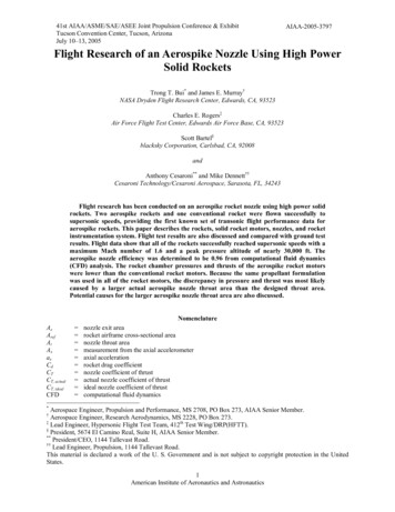
DensityOne important benefit of Cu-D composite is the lower density relative to copper and its alloys.As mentioned earlier 40 vol% of diamond in NARloy-Z can lower the density by nearly 30%.The combination of lower density and higher thermal conductivity will result in significantlylower mass for the combustion chamber liner. Actual weight savings will depend on the enginedesign. Table 5 gives the range of densities obtained in the GTE study.Thermal Cycling BehaviorThermal expansion coefficients (CTE) of diamond and copper are very different. Diamond has alower CTE than copper and its alloys and this is a potential source of thermal stresses duringheating and cooling. Any thermal cycle could potentially result in debonding at the Cu-Dinterface and loss of thermal conductivity (TC) and mechanical strength. Aaron Rape et al (Ref.9) have studied this problem and reported the results for NARloy-Z-D composites. The CTEresults are shown in Fig. 6.Fig. 6: Coefficient of thermal expansion for CuAgZr–diamond composite system showing the reductionof CTE with increasing diamond content.13
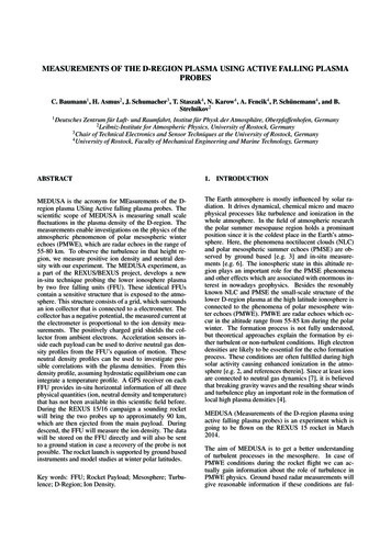
Fig. 7: Thermal conductivity results of CuAgZr–diamond samples after being exposed to thermal cycles(Ref. 9)Thermal conductivity as a function of number of thermal cycles is presented in Fig. 7. In thisfigure, Cycle 1: -55-125 C, Cycle 2: - 55-155 C and Cycle 3: -55-200 C. These temperaturesare typical for heat sink applications. The material did not suffer a loss of thermal conductivitydue to the thermal cycles suggesting that no debond occurred between diamond and copper. Thisresult is encouraging and indicative of good bond strength between ZrC and NARloy-Z matrix.Thermal cycles in a combustion chamber liner in a rocket engine will be more extreme: lowerlimit temperatures which may approach the temperature of liquid hydrogen (-253 C), or liquidmethane (-162 C) fuels used with LOX oxidiser. Liquid nitrogen cooling (LN) to -192 C is oftenused to simulate low-temperature cooling of the combustion chamber liner. At the hightemperature end of operation the chamber liner, temperature may exceed 500 C. GTE hasstudied the thermal cycling behavior of Cu-D composites in some detail (Ref. 6).To simulate high temperature cycling, a relatively thin (1-3 mm thickness) thermal conductivitysample of the ‘pure’ Cu matrix Cu-diamond composite was heated in air to 450 C in a resistancefurnace and rapidly cooled by quickly removing the heated part from the furnace and placing itdirectly onto a 1”-thick aluminum cold plate at ambient temperature. Immediately afterward, thethermal conductivity of the sample was remeasured by laser flash. Table 6 shows the effect of asingle cycle high-temperature excursion on the thermal conductivity of a ‘pure’ Cu matrix samplecontaining Vf 40% diamond, 274 micron size diamond, (full designation 274,M3.HP,PB). It canbe seen that the thermal conductivity apparently incresases slightly after the high-temperature14
thermal cycle (increase from 563 to 582 W/m.K), which may indicate measurement error ratherthan an actual change in conductivity.To simulate low-temperature cycling under service conditions using LN, the thin thermalconductivity samples were plunged into LN and allowed to equilibriate at low temperaturebefore being removed and allowed to equilibriate at room temperature prior to remeasurement ofthermal conductivity. This constituted one low-temperature thermal cycle (from RT to -192 Cand back to RT). On 1 and 3 low-temperature thermal cycles of the ‘pure’ Cu matrix sample (thatwas previously subjected to the initial high-temperature cycle in Table 6), the thermalconductivity dropped slightly by 3% of its starting value as shown in Table 7. Also shown in thetable is the change in thermal conductivity after one low-temperature cycle for a ‘pure’ Cumatrix sample containing smaller size diamond made using lower quality M1 diamond, whichshows a larger drop in thermal conductivity of 8.7% suggesting a possible debond at Cu-Dinterface.Table 6. Changes in thermal conductivity on high-temperature cycling of “pure” Cu matrix Cu-DsampleDescription274 micron size diamond,‘pure’ Cu matrix(274,M3.HP,PB).Vf% D in‘Pure’ CuStarting K(W/m.K)K after 1 cycle450⁰C, fastcool% decrease in K40563582(-) 3.5Table 7. Changes in thermal conductivity on low-temperature cycling of “pure” Cu matrix Cudiamond samplesDescription274 micron sizediamond, ‘pure’ Cumatrix(274,M3.HP,PB).137 micron sizediamond ‘pure’Cumatrix(137,M1,HP, PB)Starting K(W/m.K)K after 1 cyclequench LNK after 3cycles% decrease in Kafter one cycle5635575453420384NA8.7Data for effect of one low-temperature thermal cycle on samples of Cu-diamond with NARloy-Zmatrix alloy containing various volume loadings of diamond are shown in Table 8. Fig. 8 showsthe thermal cycling effects on thermal conductivity over five cycles for four different diamondcontents in NARloy-Z matrix. Overall there is no significant change in thermal conductivity after15
multiple cycles, confirming the good bond strength of Cu-D interface in NARloy-Z matrix.Slightly larger drops in conductivity are seen with use of lower
Based on Copper Alloys with Diamond Particle Additions Biliyar N. Bhat, Sion M. Pickard* and Todd G. Johnson* . high heat flux so that the liner surface temperatures are well below the melting point of the liner. NARloy-Z (Cu-3 wt.% Ag-0.5 wt.% Zr alloy) is the state-of-the-art material used to make the